System Analysis, Design, and Development Concepts, Principles, and Practices phần 3 ppsx
Bạn đang xem bản rút gọn của tài liệu. Xem và tải ngay bản đầy đủ của tài liệu tại đây (2.63 MB, 84 trang )
15.6 System Compliance with Its Operating Environment 155
The Consequences of Noncompliance
When a system fails to adhere to established standards, it places itself at risk with society. Society’s
response to a lack of compliance generally involves formal or informal notification, establishment
that noncompliance occurred, adjudication of the degree or noncompliance, and sentencing in
accordance with prescribed consequences or penalties. In some cases the system may voluntarily
elect to bring itself into compliance or be mandated to be compliant. In other cases, society may
ostracize or punish the instigators.
System of
Interest
(SOI
)
System of
Interest
(SOI)
Higher
Order
System
Higher
Order
System
Request for
Arbitration/
Resolution
(Stimulus)
• Competition for Resources
• Court Sy
stem
Request
Acknowledgement
(Response
)
1
2
Resolution
(Response
)
3
Exam
ples
1
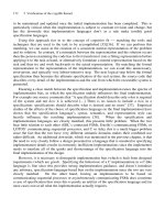
System A
(Aggressor
Role)
System B
(Defender
Role)
Hostile Action
(Stimulus)
·
Military Fighter Aircraf
t
·
Internet Security
·
Viruses & Antibiotics
Tactical
Response
(R
esponse)
4
Countermeasures
Response
(R
esponse)
2
Counter-
Countermeasures
Response
(R
esponse)
3
Examples
Figure 15.5 Issue Arbitration/Resolution System Interactions Example
Figure 15.6 Hostile Encounter Interactions Example
Simpo PDF Merge and Split Unregistered Version -
156 Chapter 15 System Interactions with Its Operating Environment
For systems such as ships, aircraft, and automobiles intentional or unintentional noncompli-
ance with the NATURAL ENVIRONMENT, HUMAN-MADE SYSTEMS, and INDUCED ENVI-
RONMENT can be very unforgiving or even worse, catastrophic.
Levels of System Interactions
System interactions with its OPERATING ENVIRONMENT occur at two levels: strategic inter-
actions and tactical interactions. Let’s explore each of these in detail.
Strategic Interactions. HUMAN-MADE SYSTEMS exhibit a higher level of behavior that
reflects a desire to advance our current condition as a means of achieving higher level vision. To
achieve the higher-level vision, humans must implement a well-defined strategy, typically long
term, based on stimuli and information extracted from out operating environment. We refer to
implementation of this long-term strategy as strategic interactions. These strategic interactions are
actually implemented via a series of premeditated missions—tactical interactions—with specific
mission objectives.
Tactical Interactions. All life forms exhibit various types of tactics that enable the system to
survive, reproduce, and sustain itself. We refer to a system’s implementation of these tactics within
the confines of its operating environment as tactical interactions. In general, this response
mechanism focuses all existing survival needs in the short term—obtaining the next meal.
System Interaction Analysis and Methodology. Depending on the compatibility and inter-
operability of an interface, consequences of the engagement may be positive, neutral, or negative.
As a system analyst or SE, your mission is to:
1. Develop a thorough understanding of the engagement participants (systems).
2. Define the most probable use cases and scenarios that characterize how the User intends
to use the system.
3. Analyze the use cases by applying natural and scientific laws of physics to thoroughly
understand the potential outcomes and consequences.
4. Specify system interface requirements that ensure engagement compatibility and inter-
operability success within cost, schedule, and technology constraints.
Adapting to the OPERATING ENVIRONMENT. Most systems are designed to perform in a
prescribed OPERATING ENVIRONMENT. There are situations whereby a system is transferred
to a new location. The net result is the need for the system to adapt to its new operating environ-
ment. Consider the following examples:
EXAMPLE 15.4
Military troops deploy to arid or snow regions. Depending on the initial conditions—namely acclimation to
the previous environment—the troops must learn to adapt to a new operating environment.
EXAMPLE 15.5
As part of a strategy for climbing a high mountain, mountain climbers travel to a series of base camps to
satisfy logistics requirements and allow their bodies time to acclimate to the thin air environment over a period
of several days.
Simpo PDF Merge and Split Unregistered Version -
System Interactions Synthesis
As an SE, you must learn to synthesize these interactions in terms of an overall system solution.
Figure 15.7 provides an illustration.
Here we have a diagram that captures the high-level interactions between the SYSTEM OF
INTEREST (SOI) (1), HIGHER ORDER SYSTEM (9) and the OPERATING ENVIRONMENT
(14). The SOI is illustrated via a “fishbone” diagram. We include in the diagram the system ele-
ments that are performance AFFECTER factors that must integrate harmoniously to achieve the
mission objectives. In combination the SOI elements produce the SYSTEM RESPONSES (8)
element, which consists of behavior, products, by-products, and services.
In operation, the SOI (1) responds to command and control guidance and direction from the
HIGHER ORDER systems element that consists of ORGANIZATION (10), ROLES AND MIS-
SIONS (11), OPERATING CONSTRAINTS (12), and RESOURCES (13) system elements. Based
on this direction, the SOI system elements interact with the OPERATING ENVIRONMENT and
provide SYSTEM RESPONSES (8) back to the OPERATING ENVIRONMENT and the HIGHER
ORDER SYSTEMS element.
15.7 GUIDING PRINCIPLES
In summary, the preceding discussions provide the basis with which to establish the guiding prin-
ciples that govern system interactions with its OPERATING ENVIRONMENT.
Principle 15.1 System interactions with its OPERATING ENVIRONMENT during an engage-
ment may be cooperative, friendly, benign, competitive, adversarial, hostile, or combination of
these.
Guiding Principles 157
PHYSICAL
ENVIRONMENT
Domain
•
HUMAN-MADE
• NATURAL
•I
NDUCED
PHYSICAL
ENVIRONMENT
Domain
•
HUMAN-MADE
• NATURAL
• INDUCED
Organization
Organization
Higher Order
Systems
Domain
Roles &
Mission
s
Roles &
Missions
SYSTEM
RESPONSES
Elemen
t
SYSTEM
RESPONSES
Elemen
t
System of Interest (SOI)
PERSONNEL
Elemen
t
PERSONNEL
Element
SUPPORT
SYSTEM Elemen
t
SUPPORT
SYSTEM Element
EQUIPMENT
Elemen
t
EQUIPMENT
Element
PROCEDURAL
DATA Elemen
t
PROCEDURAL
DATA Element
FACILITIES
Elemen
t
FACILITIES
Element
MISSION RESOURCES
Elemen
t
MISSION RESOURCES
Elemen
t
Operating
Constraint
s
Operating
Constraints
Resources
Resources
1
2 3 4
5 6 7
8
9
10 11 12 13
14
Figure 15.7 System Element Contributions to Overall System Performance
Simpo PDF Merge and Split Unregistered Version -
158 Chapter 15 System Interactions with Its Operating Environment
Principle 15.2 Every system responds to stimuli and cues in its OPERATING ENVIRONMENT
with behavioral actions, products, by-products, services, or combinations thereof.
15.8 SUMMARY
During our discussion of system interactions with its operating environment, we described a system’s inter-
actions via the Behavioral Responses Model. A system’s responses are driven by strategic and tactical inter-
actions related to opportunities and threats in the environment. Systems generally interact with cooperative,
benign, competitive, or aggressor systems. Based on those responses, we indicated how a system might employ
countermeasures and counter-countermeasures to distract, confuse, defend or interact with other systems. We
concluded our discussion by highlighting the context of the OPERATING ENVIRONMENT based on the
SYSTEM OF INTEREST perspective.
GENERAL EXERCISES
1. Answer each of the What You Should Learn from This Chapter questions identified in the Introduction.
2. Refer to the list of systems identified in Chapter 2. Based on a selection from the preceding chapter’s
General Exercises or a new system selection, apply your knowledge derived from this chapter’s topical
discussions.
(a) If applicable, identify whether the system operates by a closed loop or an open loop.
(b) If by a closed loop, how does the system process stimuli and cues and provide measured responses.
3. Identify external systems that interface with your product or service. Characterize them in terms of coop-
erative, benign, or adversarial.
4. What vulnerabilities or susceptibilities does your system, product, or service have to threats in its operat-
ing environment? What capabilities, tactics, or procedures have been added to the product to minimize vul-
nerability or susceptibility?
Simpo PDF Merge and Split Unregistered Version -
Chapter 16
System Mission Analysis
16.1 INTRODUCTION
The primary purpose of any system is to satisfy individual or organizational objectives with an
expected tangible or intangible return on investment (ROI). These objectives may range from the
quality of life such as happiness, entertainment, education, and health to the basic necessities of
life—organizational survival, profitability, food, and shelter. The act of striving to accomplish these
objectives can be summarized in one operative term, mission.
The accomplishment of individual and organizational missions requires the employment of
systems, products, and services that leverage human capabilities. Selection or acquisition of those
systems begins with understanding the WHO, WHAT, WHEN, WHERE, and HOW system User(s)
plan to accomplish the mission(s). We refer to activities required to develop this understanding as
a mission analysis.
This chapter introduces the key elements of the mission analysis and provides the foundation
for deriving system capabilities and requirements. Our discussions focus on the key attributes of a
mission.
What You Should Learn from This Chapter
1. What are the key tasks required to define a system mission?
2. What is a Mission Event Timeline (MET)?
3. What is mission task analysis?
4. What are the primary mission phases of operation?
5. What system related operations and decisions are performed during the pre-mission phase?
6. What system related operations and decisions are performed during the mission phase?
7. What system related operations and decisions are performed during the postmission?
8. What are the key decisions that occur within mission phases and trigger the next phase?
Definitions of Key Terms
• Mission A pre-planned exercise that integrates a series of sequential or concurrent opera-
tions or tasks with an expectation of achieving outcome-based success criteria with quan-
tifiable objectives.
• Mission Critical System “A system whose operational effectiveness and operational suit-
ability are essential to successful completion or to aggregate residual (mission) capability. If
System Analysis, Design, and Development, by Charles S. Wasson
Copyright © 2006 by John Wiley & Sons, Inc.
159
Simpo PDF Merge and Split Unregistered Version -
this system fails, the mission likely will not be completed. Such a system can be an auxil-
iary or supporting system, as well as a primary mission system.” (Source: DSMC—adapted
from Glossary: Defense Acquisition Acronyms and Terms)
• Mission Needs Statement (MNS) “A nonsystem specific statement that identifies an orga-
nizational operational capability need.” (Source: Adapted from DSMC T&E Mgt. Guide,
Appendix B, DoD Glossary of Test Terminology, p. B-20-21)
• Mission Reliability “The probability that a system will perform its required mission criti-
cal functions for the duration of a specified mission under conditions stated in the mission
profile.” (Source: Glossary: Defense Acquisition Acronyms and Terms)
• Operational Constraints “Initially identified in the Mission Need Statement (MNS). As a
minimum, these constraints will consider the expected threat and natural environments, the
possible modes of transportation into and within expected areas of operation, the expected
(operating) environment, operational manning limitations, and existing infrastructure support
capabilities.” (Source: Adapted from DSMC—Glossary: Defense Acquisition Acronyms and
Terms)
• Phase of Operation A high-level, objective-based abstraction representing a collection
of SYSTEM OF INTEREST (SOI) operations required to support accomplishment of a
system’s mission. For example, a system has pre-mission, mission, and postmission
phases.
• Point of Delivery A waypoint or one of several waypoints designated for delivery of mission
products, by-products, or services.
• Point of Origination or Departure The initial starting point of a mission.
• Point of Termination or Destination The final destination of a mission.
• Task Order A document that: 1) serves as triggering event to initiate a mission and 2)
defines mission objectives and performance-based outcomes.
• Time Requirements “Required functional capabilities dependent on accomplishing an
action within an opportunity window (e.g., a target is vulnerable for a certain time period).
Frequently defined for mission success, safety, system resource availability, and production
and manufacturing capabilities.” (Source: Former MIL-STD-499B Draft)
• Timeline Analysis “Analytical task conducted to determine the time sequencing between
two or more events and to define any resulting time requirements. Can include task/time-
line analysis. Examples include:
a. A schedule line showing key dates and planned events.
b. An engagement profile detailing time based position changes between a weapon and its
target.
c. The interaction of a crewmember with one or more subsystems.” (Source: Former MIL-
STD-499B Draft)
• Waypoint A geographical or objective-based point of reference along a planned roadmap
to mark progress and measure performance.
16.2 MISSION DEFINITION METHODOLOGY
Organizational and system missions range from simple tasks such as writing a letter to performing
highly complex International Space Station (ISS) operations, managing a government. Regardless
of application, mission analysis requires consideration of the steps specified below:
160
Chapter 16 System Mission Analysis
Simpo PDF Merge and Split Unregistered Version -
Step 1: Define the primary and secondary mission objective(s).
Step 2: Develop a mission strategy.
Step 3: Define phase-based operations and tasks.
Step 4: Create a Mission Event Timeline (MET).
Step 5: Bound and specify the mission OPERATING ENVIRONMENT interactions.
Step 6: Identify outcome-based system responses to be delivered.
Step 7: Identify mission resources and sustainment methods.
Step 8: Perform a mission task analysis.
Step 9: Assess and mitigate mission and system risk.
Let’s explore each of these steps in more detail.
Step 1: Define the Primary Mission Objective(s)
People often mistakenly believe that missions begin with the assignment of the “mission” to be
accomplished. However, missions are action-based applications of systems, products, or services
to solution spaces for the purposes of resolving or eliminating all or a portion of an operational
need—meaning a problem or opportunity space. These actions may be oriented toward a single
event or occur via one or more reusable missions over a period of time. Consider the following
examples:
EXAMPLE 16.1
The NASA Space Shuttle’s external tank (ET), which is expendable, represents a single event mission applica-
tion. On completion of its mission, the ET is jettisoned and burns up in the atmosphere.
EXAMPLE 16.2
NASA’s Space Shuttle Orbiter vehicle performs via a series of mission applications to ferry components of
the International Space Station (ISS) for integration and support of science.
As with any system, the initial step in performing mission analysis is to understand the underlying
motivation and primary/secondary objectives to be accomplished. Mission objectives are charac-
terized by several attributes. For our discussion the two primary attributes are:
1. Outcome-based results to be achieved.
2. Mission reliability required to achieve those results.
Identify the Outcome-Based Results. When you define a mission objective, the first step is
to define WHAT results are expected to be produced. The results should be:
1. Preferably tangible as well as measurable, testable, and verifiable.
2. Contribute to accomplishment of HIGHER ORDER SYSTEM tasking.
Determine the Mission Reliability. Human systems, despite careful planning and execution,
are not infallible. The question is: Given resource constraints, WHAT is the minimum level of level
of success you are willing to accept to provide a specified return on investment (ROI). From an SE
16.2 Mission Definition Methodology 161
Simpo PDF Merge and Split Unregistered Version -
point of view, we refer to the level of success as mission reliability. Mission reliability is influenced
by internal EQUIPMENT element failures or over/undertolerance conditions, human operator
performance (judgment, errors, fatigue etc.) and interactions with OPERATING ENVIRONMENT
entities and threats.
Mission reliability is the probability that a system will successfully accomplish a mission
of a specific duration in a prescribed OPERATING ENVIRONMENT and accomplish objectives
without a failure event. Depending on the system application, 100% mission reliability may be pro-
hibitively expensive, but a 90% mission reliability may be affordable.
Authors Note 16.1 Since reliability ultimately has a cost, establish an initial reliability esti-
mate as simply a starting point and compute the cost. Some Acquirers may request a Cost-as-an-
Independent-Variable (CAIV) plot of cost as a function of capability or reliability to determine what
level of capability or reliability is affordable within their budgetary constraints.
Specify and Bound the Required Level of Performance. Once the mission reliability is
established, system designers can proceed with identifying the level of performance required of the
system elements, such as EQUIPMENT and PERSONNEL, subject to cost, schedule, and risk
constraints.
Once we establish the primary mission objectives, the next step of mission analysis is to define
the mission profile.
Step 2: Develop a Mission Strategy
A mission begins with a point of origination and terminates at a point of destination. As end-to-
end boundary constraints, the challenge question is: HOW do we get from the point of ORIGINA-
TION to the point of DESTINATION?
We begin by establishing a strategy that leads to a mission profile or a roadmap that charts
progress through one or more staging and control points, or waypoints. A waypoint represents a
geographical location or position, a point in time, or objective to be accomplished as an interim
step toward the destination, as illustrated in Figure 16.1. Each phase of operation is decomposed
into one or more objectives focused on the pathway to successful completion of the mission. Con-
sider the following examples:
162
Chapter 16 System Mission Analysis
Destination
or Point of
Termination
Point of
Origination
Staging, Control, or Way Points
t
0
t
2
t
4
t
6
t
1
t
5
t
3
OPERATING ENVIRONMENT Conditions
Objective #2
Objective #3
Objective #6
0 62 413 5
Objective #1
Objective #4
Objective #5
Time
Initial Conditions
Pre-Mission Phase Mission Phase
Post-Mission Phase
Figure 16.1 Operational Concept Timeline Example
Simpo PDF Merge and Split Unregistered Version -
EXAMPLE 16.3
A ship cruise line has several ports of call or waypoints on its scheduled item erary for a 7-day voyage. A
package delivery service has performance-based deliveries or waypoints for a delivery route.
Step 3: Define Phase-Based Operations and Tasks
Human-made systems, especially cyclical systems, sequence through three sets of objective-based
actions to accomplish a mission: 1) prepare for the mission, 2) conduct the mission, and 3) perform
post-mission actions and processing. We characterize these objectives as the pre-mission, mission,
and post-mission phases of operation. For those systems to be placed in storage following the
mission, an interim phase—storage—may be added.
When implemented, the SYSTEM OF INTEREST (SOI) consisting of the MISSION SYSTEM
and SUPPORT SYSTEM must provide capabilities and levels of performance to support these
phases of operation. Each phase consists of use case based operations and tasks, all focused on
accomplishing the phase outcome-based performance objective(s).
Step 4: Create a Mission Event Timeline (MET)
Once we establish the waypoints, the next task is to determine waypoint time constraints. We refer
to these time constraints as milestone requirements derived from the mission event timeline (MET).
The MET can be presented as a simple, high-level schedule down to a highly detailed, multi-level,
networked schedule.
Guidepost 16.1 Mission analysis up to this point has focused on the “ideal” mission—namely
what we intend to accomplish. However, to accomplish a mission, the MISSION SYSTEM must
interact with the OPERATING ENVIRONMENT and its elements, consisting of HUMAN-MADE
systems, the NATURAL ENVIRONMENT, and the INDUCED ENVIRONMENT. This brings us to
our next mission analysis task: bound and specify the OPERATING ENVIRONMENT.
Step 5: Bound and Specify the Mission OPERATING
ENVIRONMENT Interactions
Once the basic mission is defined, the next step is to bound and specify its OPERATING ENVI-
RONMENT. Throughout the pre-mission, mission, and postmission phases, the SOI interacts with
external systems within its OPERATING ENVIRONMENT. These systems may include friendly
systems, benign systems, or hostile threats and harsh environmental conditions.
Collectively the mission analysis identifies and analyses these systems, their roles
relative to the mission, and what impacts they may have on performing the mission and accom-
plishment of its performance objectives. For example, what systems does the MISSION SYSTEM
need to: 1) communicate with, 2) perform deliveries and transfers to, and 3) interact with on an
encounter/engagement basis along with the mission profile.
Guidepost 16.2 Our earlier discussion emphasized the need to identify the outcome-based
results of the mission. The question is: WHAT products, by-products, or services is the system
required to PRODUCE or AVOID to achieve the OUTCOME-based results. This brings us to the
next task: identify system responses.
16.2 Mission Definition Methodology 163
Simpo PDF Merge and Split Unregistered Version -
Step 6: Identify Outcome-Based System Responses
Throughout all phases of the mission, an SOI produces a series of behaviors, products, by-
products, and services to satisfy internal and external requirements. Internal requirements include
performance monitoring, resource consumption, and payload/cargo manifests. External require-
ments include the examples listed in Table 16.1.
Step 7: Identify Mission Resources and Sustainment Methods
Human-made systems have finite resource capacities that require replenishment and refurbishment.
Depending on the mission operating range of the system relative to its current mission application,
mission analysis must consider HOW the system’s expendables and consumables will be resup-
plied and replenished. Operationally, the question is: How will the organization sustain and main-
tain the mission from beginning to end?
Step 8: Perform a Mission Task Analysis
Throughout the pre-mission, mission, post-mission phases, specific operational tasks must be per-
formed to accomplish the phase-based mission objectives. These tasks ultimately provide the basis
for capabilities the SOI must provide to accomplish the mission. Therefore the mission analysis
should:
1. Identify the high-level outcome-based mission tasks to be performed.
2. Synchronize those tasks to the Mission Event Timeline (MET).
3. Identify the task performance-based objectives.
Step 9: Assess and Mitigate Mission and System Risk
Some systems are required to perform missions in harsh OPERATING ENVIRONMENTs that may
place the system at risk to threats, not only in completing its mission but also in returning safely
to its home base. Consider the following example:
EXAMPLE 16.4
Loose, hidden objects on a lawn can cause injury to people and damage a lawnmower blade and engine. Birds,
ducks, and geese pose threats to airports and aircraft in flight. Loose objects and debris thrown into the air by
vehicles on the road can cause injury to others and damage to vehicles. Unprotected computer systems are
vulnerable to viruses.
164 Chapter 16 System Mission Analysis
Table 16.1 Examples of mission requirements derived from analysis of external systems
Type of External System Example Sources of Requirements
Friendly or cooperative systems Communications
Deliverable items, etc.
Benign systems Communications
Detection and avoidance
Evasive tactics, etc.
Hostile or Adversarial systems Rules of engagement
Detection and avoidance
Countermeasures/counter-counter measures
Aggressive/defensive actions, etc.
Simpo PDF Merge and Split Unregistered Version -
Risks assessments include considerations of system vulnerability, susceptibility, survivability, and
maintainability. Most people tend to think in terms of external benign, adversarial, or hostile
systems that may be threats to the system. However, since a system interacts with itself, it can also
be a threat to itself. Recall from our discussion of the architecture of systems in Chapter 8 how a
system interacts with: 1) its OPERATING ENVIRONMENT and 2) itself. Analytically, the sources
of these threats begin with the MISSION SYSTEM and SUPPORT SYSTEM elements—comprised
of PERSONNEL, EQUIPMENT, MISSION RESOURCES, PROCEDURAL DATA, SYSTEM
RESPONSES, and FACILITIES. Consider the following EQUIPMENT system element examples.
EXAMPLE 16.5
Failed automobile components, such as a blown tire, can cause a driver to loose control of the vehicle while
driving. Failures in an aircraft’s flight control system or broken blades in a jet engine fan can force and emer-
gency landing or have catastrophic consequences.
Internal failures or degraded performance also has negative impacts on system performance that ulti-
mately translates into mission failure or degree of success. Perhaps one of the most notable examples is the
Apollo 13 catastrophe. Mission analysis should identify those areas in system capabilities that may be vul-
nerable or susceptible to external internal threats, especially for mission critical components.
Author’s Note 16.1 Internal threat analysis is typically performed via failure modes and effects
analysis (FMEA). For mission critical components, the FMEA may be expanded into a failure
modes, effects, and criticality analysis (FMECA) that assesses the degree of criticality.
16.3 GUIDING PRINCIPLES
In summary, the preceding discussions provide the basis with which to establish the guiding prin-
ciples that govern mission analysis.
Principle 16.1 Every system mission must accomplish one or more organizational performance
objectives.
Principle 16.2 Human-made systems have three primary phases of operation: pre-mission,
mission, and post-mission; an interim phase may be further required for some systems.
Principle 16.3 Every system phase of operation must satisfy one or more outcome-based per-
formance objectives associated with accomplishment of an overall system mission and its per-
formance objectives.
Principle 16.4 Mission success requires five key elements: a purpose, resources, a reasonably
achievable outcome-based performance objective(s), a Mission Event Timeline (MET), and a will-
ingness to perform. Where there is no willingness to act, the other elements are meaningless.
16.4 SUMMARY
Our discussion of mission analysis highlighted several key points that require emphasis:
• Every system concept consists of interactions of abstract entities derived from the System Element
Architecture: 1) SYSTEM OF INTEREST (SOI) consisting of the MISSION SYSTEM and the
SUPPORT SYSTEM and 2) the OPERATING ENVIRONMENT.
16.4 Summary
165
Simpo PDF Merge and Split Unregistered Version -
• Each mission begins with a point of origination and concludes with a destination or point of termina-
tion with intervening staging, control, or waypoints based on specific objectives and Mission Event
Timeline (MET) events.
• Between the point of origination and point of termination, some missions may require interim way-
points or delivery points that satisfy specific mission objectives.
• Every mission must be founded on an operational strategy that defines HOW the system elements—
namely PERSONNEL, EQUIPMENT, and FACILITIES—will be deployed and employed at critical
staging events to accomplish mission objectives constrained by a Mission Event Timeline (MET).
• Every mission is characterized by at least three mission phases of operation: 1) pre-mission, 2) mission,
and 3) post-mission.
• During each phase of operation, system element interactions must be orchestrated and synchronized in
accordance with mission objectives and a Mission Event Timeline (MET).
• Every mission requires mission critical capabilities with a minimum level of performance to be pro-
vided by the system elements—namely PERSONNEL, EQUIPMENT, and MISSION RESOURCES—
to achieve a specified outcome.
GENERAL EXERCISES
1. Answer each of the What You Should Learn from This Chapter questions identified in the Introduction.
2. Refer to the list of systems identified in Chapter 2. Based on a selection from the preceding chapter’s
General Exercises or a new system selection, apply your knowledge derived from this chapter’s topical
discussions. Identify the following:
(a) How many different missions does the system perform?
(b) What are those missions?
(c) Pick two missions and perform a mission analysis using the methodology described in this section.
ORGANIZATIONAL CENTRIC EXERCISES
1. Select a contract program within your organization. Interview program personnel to understand what form
of mission analysis was performed on the program.
(a) Was the mission analysis required as a contract deliverable? If so, when was it required to be deliv-
ered? Were subsequent updates required? Was there a required outline format?
(b) Who performed the mission analysis?
(c) How was the mission analysis documented?
(d) What was the most difficult parts of the analysis to accomplish?
(e) In what ways do program personnel believe the analysis benefit the program?
(f) What would you do differently next time?
(g) How did program and executive management view the importance of the analysis?
(h) Were the right amount of resources and expertise applied to accomplish the task?
(i) What were the shortcomings, if any, of the end product?
REFERENCES
166 Chapter 16 System Mission Analysis
Defense Systems Management College (DSMC). 1998.
DSMC Test and Evaluation Management Guide, 3rd ed.
Defense Acquisition Press Ft. Belvoir, VA.
Defense Systems Management College (DSMC). Glossary:
Defense Acquisition Acronyms and Terms, 10th ed.
Defense Acquisition University Press Ft. Belvoir, VA.
2001.
MIL-STD-499B (cancelled draft). 1994. Systems Engineer-
ing. Washington, DC: Department of Defense (DoD).
Simpo PDF Merge and Split Unregistered Version -
Chapter 17
System Use Cases and Scenarios
17.1 INTRODUCTION
From an SE perspective the challenge in developing systems is being able to translate mission
objectives, operations, and tasks into a set of capability requirements that can be transformed into
a physical design solution. Most organizations and individuals attempt to make a quantum leap
from the mission objectives to writing text requirements into the System Performance Specifica-
tion (SPS). This is typically accomplished without understanding:
1. What problem space the User is attempting to solve.
2. How they intend to deploy and employ the solution space system to perform missions to
address all or a portion of the problem space.
As systems become more complex, they require a solution development methodology that is easily
understood by Acquirers, Users, and System Developers. One method is to employ system use cases
and scenarios to bridge the gap between mission objectives and specification requirements.
What You Should Learn from This Chapter
• What is a system use case?
• What are the attributes of a use case?
• What is a use case analysis and how do you perform one?
• How do use cases relate to system capability requirements?
Definitions of Key Terms
• Actor “A role of object or objects outside of a system that interacts directly with it as part
of a coherent work unit (a use case). An Actor element characterizes the role played by an
outside object; one physical object may play several roles and therefore be modeled by
several actors.” (UML Notation Guide, para. 6.1.2, p. 75)
• Operational Scenario A hypothesized narrative that describes system entity interactions,
assumptions, conditions, activities, and events that have a likelihood or probability of actu-
ally occurring under prescribed or worst-case conditions.
• Sequence Diagram “A diagram that represents an interaction, which is a set of messages
exchanged among objects within a collaboration to effect a desired operation or result.”
(UML Notation Guide, para. 7.2.1, p. 80)
System Analysis, Design, and Development, by Charles S. Wasson
Copyright © 2006 by John Wiley & Sons, Inc.
167
Simpo PDF Merge and Split Unregistered Version -
• Use Case A statement that expresses how the User envisions deploying, operating, sup-
porting, or disposing of a system, product, or service to achieve a desired performance-based
outcome.
• Use Case Diagram “A graph of actors, a set of use cases enclosed by a system boundary,
communication (participation) associations between the actors and the use cases, and gen-
eralizations among the use cases.” (UML Notation Guide, para. 6.1.2, p. 75)
• Use Case Scenario A set of conditions a MISSION SYSTEM use case may encounter in
its OPERATING ENVIRONMENT that requires a unique set of capabilities to produce a
desired result or outcome. Scenarios include considerations of HOW a User or threat might
apply, misapply, use, misuse, or abuse a system, product, or service.
17.2 UNDERSTANDING THE ANALYTICAL
CONTEXT OF USE CASES AND SCENARIOS
A reference framework that illustrates the context of use cases and scenarios and their importance
is provided in Figure 17.1. Note that the entity relationships in the figure are partitioned into three
domains: an Operations Domain, an Analysis Domain, and an Engineering Domain. Based on this
framework, let’s characterize these relationships.
1. Each mission is assigned at least one or more mission objectives.
2. Each mission objective is accomplished by an integrated set of mission operations per-
formed by the MISSION SYSTEM and SUPPORT SYSTEM.
3. Each MISSION SYSTEM and SUPPORT SYSTEM operation is decomposed into hierar-
chical chains of sequential and concurrent tasks.
4. Each task is performed and measured against one or more performance standards and imple-
mented via at least one or more use cases.
168
Chapter 17 System Use Cases and Scenarios
Use Cases
●
●
●
Deployment
O & S
Disposal
Use Case
Scenarios
●
Application
●
Proper Use
●
M
isuse
●
Abuse
Accomplished by
1 *
Address
Characterize
Achieve
Bounded by
1 *
Operations
MISSION SYSTEM
S
UPPORT SYSTEM
Bounded by
1 *
Characterize
Tasks
D
ecomposed into
1 *
Operations Domain Analysis Domain Engineering Domain
Mission
Objective(s)
Bound
Characterized by
1 *
Required
Operational
Capabilities
Requires
1 *
Bounded by
1 *
Performance
Requirements
Bound
Performance
Standards
Measured by
1 *
●
●
Figure 17.1 System/Product Use Cases and Scenarios Entity Relationships
Simpo PDF Merge and Split Unregistered Version -
5. Each use case is bounded by at least one or more use case scenarios.
6. Each use case scenario represents HOW the use case can be applied, used, misused, abused,
etc. and is bounded and specified by at least one or more required operational capabilities.
7. Each required operational capability identifies WHAT the system, product, or service must
perform to fulfill each use case and accommodates various use case scenarios and is quan-
tified by at least one or more performance requirements.
This introductory framework establishes the backdrop for our discussion of system use cases and
scenarios.
17.3 WHAT ARE USE CASES?
A use case is characterized by a set of attributes that describe HOW the User might deploy, operate,
support, or dispose of the system. The attributes, which serve as a checklist for developing use
cases, include:
• Unique identifier
• Objective
• Outcome-based results
• Assumptions
Initial state
Final state
Environmental conditions
Preceding circumstances (optional)
Operating constraints
External inputs
Resources
Event-based timeline
Frequency of occurrence and utility priorities
• Processing capabilities
• Scenarios and consequences
Probability of occurrence
Use case scenario actors
Stimuli and cues
Consequences
Compensating/mitigating actions
Given this list, let’s briefly describe each one and its contribution to the characterization.
Attribute 1: Unique Identifier
Each use case should have its own unique identity and not overlap, conflict, or duplicate other use
cases. Therefore each use case should be tagged with its own unique identifier and title.
Attribute 2: Objective
Each use case must have at least one or more outcome-based performance objectives.
17.3 What Are Use Cases? 169
Simpo PDF Merge and Split Unregistered Version -
Attribute 3: Outcome-Based Results
Use cases should produce at least one or more system/entity behaviors, products, by-products, or
services that may be tangible or intangible to achieve the desired outcome-based objective.
Attribute 4: Assumptions
The formulation of use cases requires that SEs make assumptions that characterize the initial con-
ditions that form the basis for initiating a use case. Assumptions include the following:
Initial State. The INITIAL state of a use case represents the assumed physical operational state
of the system, product, or service when the use case is initiated.
Final State. The FINAL state represents the desired physical or operational state of the system
when the desired outcome has been achieved.
Environmental Conditions. The current environmental conditions specify and bound the
OPERATING ENVIRONMENT conditions that exist when a system, product, or service use case
is initiated.
Preceding Circumstances (Optional). For some applications, the circumstance or sequence
of events leading up to the initiation of a use case need to be identified. Preceding circumstances
provide a basis for documenting this assumption.
Operating Constraints. For some use cases the system, product, or service may have opera-
tional constraints such as organizational policies, procedures, task orders; local, federal, state, and
international regulations or statutory laws; or public opinion; or a Mission Event Timeline (MET).
Operational constraints thus serve to bound or restrict the acceptable set of corporate, moral, ethical,
or spiritual actions allowed for a use case.
External Inputs. Every system, product, or service processes external inputs to add value to
achieve the specified outcome.
Resources. Every system, product, or service requires MISSION RESOURCES to perform its
mission. MISSION RESOURCES are typically finite and are therefore constrained. The resources
attribute documents what types of resources (i.e. expendables or consumables) are required to
sustain system/entity operations.
Event-Based Timeline. Use cases may require a Mission Event Timeline (MET) to synchro-
nize the planned actions or intervention of human operators or expected responses from the system
or its operators.
Frequency of Occurrence and Utility Priorities. Every use case has a cost and schedule for
development, training, implementation, and maintenance. The realities of budgetary cost and sched-
ule limit the number of use cases that can be practically implemented. Therefore, prioritize use
cases and implement those that maximize application and safety utility to the User.
Note that we said, to maximize application and safety utility. If you prioritize use cases, emer-
gency capabilities and procedures should have a very remote frequency of occurrence. Neverthe-
less, they can be the most critical. As is the case in trade study evaluation criteria, you may need
to analytically express utility in terms of a multiplicative factor. Instead of assigning a 1 (low) to
170
Chapter 17 System Use Cases and Scenarios
Simpo PDF Merge and Split Unregistered Version -
5 (high) weighting factor priority to each use case, multiply the factor by a level of criticality from
1 (low) to 5 (high) to ensure the proper visibility from a safety perspective.
Commercial organizations produce products and services to sell in the marketplace at a profit
and sustain the business operations for the long term. Organizational products and services MUST
be SAFE for the Users to deploy, operate, and support. Hypothetically, you could focus all resources
on safety features and produce a product that is so burdened with safety features that it has no
application utility to the User.
Although our discussion focuses on the development of a product or service, remember that
the system has other elements than just EQUIPMENT (PERSONNEL, PROCEDURAL DATA,
etc.). So, when confronted with increasing design costs, there may be equally effective alternatives
for improving safety such as operator certification, training and periodic refresher training, cau-
tionary warning labels, and supervision that may not require product implementation.
Attribute 5: Processing Capabilities
The heart of a use case centers on stimulus-response processing for a specified set of conditions to
produce the desired or required outcome. Some domains refer to this as a transfer or response func-
tion. Consider the following example:
EXAMPLE 17.1
A photovoltaic or solar cell transforms sunlight into electrical energy.
Author’s Note 17.1 Remember, the context here is a simple box representing a system or item
at any level of abstraction with input(s) and output(s). Focus on simplification of the solution space.
Avoid attempting to define processing for multiple levels simultaneously.
Attribute 6: Scenarios and Consequences
As humans, we tend to be optimistic and ideally believe that everything will be successful. While
this is true most of the time, uncertainties do occur that create conditions we have not planned for
operationally or in terms of system, product, or service capability. Once a use case is identified,
ask the question: WHEN the User employs this use case:
1. WHAT can go wrong that we haven’t anticipated?
2. WHAT are the consequences of failure and how do we mitigate them?
We refer to each of these instances as use case scenarios and consequences? Consider the follow-
ing example:
EXAMPLE 17.2
Suppose that we are designing a compact disk (CD) or digital video disk (DVD) player. Ideally, the high-level
CD/DVD use case describes a User inserting the CD/DVD into the player—and magic happens! The User
gets the result, be it music or a movie. The User has thus a use case scenario with a POSITIVE outcome.
Now, what happens if the User inserts the CD/DVD upside down? The User has a use case scenario with a
NEGATIVE outcome. This leads to the question: When we design the CD/DVD device, how should the User
be advised of this situation? If we add notification capability to the device, development costs increase. In
contrast, the LOW-COST solution may be to simply inform the User via the product manual about the con-
vention of ALWAYS inserting the CD/DVD so that the title faces upward.
17.3 What Are Use Cases?
171
Simpo PDF Merge and Split Unregistered Version -
Probability of Occurrence. Once use case scenarios are identified, we need to determine the
probability of occurrence of each one. As in the earlier discussion of use case priorities, scenarios
have a probability of occurrence. Since additional design features have a cost, prioritize scenarios
with User safety as a predominant consideration.
Use Case Scenario Actors. Our discussion up to this point has focused on the WHAT is most
likely or probable to occur: use cases or scenarios. The key question is: WHO or WHAT are the
interacting entities during use cases and scenarios. The Unified Modeling Language (UML
®
)
characterizes these entities as “actors.”
Actors can be persons, places, real or virtual objects, or events. UML
®
represents actors as
stick figures and use cases as ellipses, as shown in Figure 17.2.
• User 1 (actor) such as a system administrator/maintainer interacts with use cases 1 through 3.
• User 2 (actor) interacts with use cases 1 and 2 (capabilities).
• User 3 (actor) interacts with use case 3 (capabilities).
In our previous example, the actors include User, CD/DVD, and CD/DVD player.
Stimuli and Cues. Use cases are initiated based on a set of actions triggered by system
operator(s), external systems, or the system. Consider the following stimulus–response actions:
• The User or an external system initiates one or more actions that cause the system to respond
behaviorally within a specified time period.
• The system notifies the User to perform an action—to make a decision or input data.
• The User intervenes or interrupts ongoing actions by the system.
Each of these examples represents instances whereby the User or System stimulates the other to
action. Figure 17.3 illustrates such a sequence of actions using a UML sequence diagram.
172 Chapter 17 System Use Cases and Scenarios
Use Case #2
Use Case #3
Use Case #1
User #2
(Actor)
MISSION SYSTEM
User #1
(Actor)
User #3
(Actor)
Where: UML
®
= Unified Modeling Language
Figure 17.2 UML
®
Use Case Diagram
Simpo PDF Merge and Split Unregistered Version -
Scenario Consequences. Each use case and scenario produces an outcome that may have
consequences. Consider the following example:
EXAMPLE 17.3
If scenario X occurs and the operator or system responds in a specified manner, instabilities and
perturbations may be induced into the system that may have NEGATIVE consequences. Therefore each use
case and scenario should identify the potential consequences of proper use/misuse, application/misapplication,
and abuse.
Compensating/Mitigating Actions. Given the set of consequences identified for use cases
and use case scenarios, we need to identify what compensating/mitigating actions should be
incorporated into the system, product, or service to eliminate or minimize the effects of a
NEGATIVE outcome consequences. Consider the following example:
EXAMPLE 17.4
Suppose that we are to design a car. Since a car can collide with other vehicles, walls, or trees, a generalized
interface solution of the car body-to-external system is insufficient. An analysis of use cases and use case sce-
narios suggests that passengers can lose their lives or sustain injuries in a collision. So a specialized interface
consisting of a bumper is added to the car frame as a compensating/mitigating action. However, impact tests
reveal that the bumper is inadequate and requires yet a more specialized solution including the following
sequences of design actions:
Design action 1: Incorporate shock absorbers into the vehicle’s bumpers.
Design action 2: Install and require use of seat belts.
Design action 3: Install an air bag system.
Design action 4: Install an anti-lock braking system (ABS).
Design action 5: Specify proper vehicle operating procedures.
Design action 6: Increase driver awareness to drive safely and defensively.
17.3 What Are Use Cases?
173
SUBSYSTEM
1
SUBSYSTEM
2
1: XXXXXX
2: XXXXXX
3: XXXXXX
4: XXXXXX
SYSTEM OF INTEREST (SOI)
System
Operator
Figure 17.3 UML
®
Use Case Sequence Diagram
Simpo PDF Merge and Split Unregistered Version -
17.4 USE CASE ANALYSIS
Each use case and its most likely or probable scenarios represent a series of anticipated interac-
tions among the actors. Once the scenarios and actors are identified, system analysts need to under-
stand the most likely or probable interactions between the system or entity of interest and external
systems within its OPERATING ENVIRONMENT.
UML
®
tools are useful in understanding the stimuli, cues, and behavioral responses between
interacting systems. Sequence diagrams serve as a key tool. Sequence diagrams consist of actors
and lifelines as illustrated in Figures 2.5 and 17.3.
• Actors Consist of entities at a given level of abstraction—such as SYSTEM, PRODUCT, and
SUBSYSTEM—and external systems within the abstraction’s OPERATING ENVIRON-
MENT. For example, a SUBSYSTEM use case might depict its operator(s), if applicable,
and external systems such as other SUBSYSTEMS, and PHYSICAL ENVIRONMENT
conditions.
• Lifeline Consists of a vertical line to represent time relative processing. Bars are placed
along the lifeline to represent entity activities or processing of external inputs, stimuli, or
cues and behavioral responses.
• Swim Lanes Consist of the regions between the actor lifelines for illustrating sequential
operations, tasks, products, by-products, or services interactions and exchanges and between
each actor.
To illustrate HOW these are employed, consider the following example:
EXAMPLE 17.5
Let’s suppose a User (actor) interacts with a calculator (actor) to accomplish a task to perform a mathemati-
cal calculation and communicate the results. Figure 17.4 provides a simple illustration of the interaction.
Observe that Figure 17.4 is structurally similar to and expands the level of detail of Figure 17.3. To keep the
example simple, assume the calculator consists of two SUBSYSTEMS, 1 and 2.
The User and each of the SUBSYSTEMS have an INITIAL State and FINAL State and conditional
loops that cycle until specific decision criteria are met to terminate operation. We assume each of
the SUBSYSTEM activities include wait states for inputs. When inputs arrive, processing is per-
formed, and control is passed to the next activity. Here’s how a potential use case scenario might
be described.
• SUBSYSTEM 1 performs Activity 20 to await user inputs via the keyboard.
• When the System Operator Activity 10 enters data as Output 10, Activity 20 accepts
the operator keyboard entries and converts the information into machine-readable code as
Output 20.
• SUBSYSTEM 2 performs: 1) Activity 30 to await data inputs and 2) Activity 31 to perform
the required computation and output the mathematical results as Output 31.
• In the interim SUBSYSTEM 1 Activity 21: 1) awaits Output 31 results, 2) converts the results
into meaningful operator information, and 3) displays the results as Output 21.
• Following data entry (i.e., Activity 10), the System Operator performs Activity 11 to: 1) await
Output 21 results, 2) record the results, and 3) communicate the results as Output 11.
These cycles continue until the calculator is turned off, which is the FINAL State.
174 Chapter 17 System Use Cases and Scenarios
Simpo PDF Merge and Split Unregistered Version -
How Many Use Cases?
A key question people often ask is: How many use cases are required for a system? There are no
magic answers; 10 through 30 use cases might be average. Some highly complex systems may just
have 5 or 6; others, 10 to 20. All depends on the individuals and organizations involved. Some
want simplicity to keep the number small; others want detailed lists. Keep in mind that a system
may have 5 to 8 primary use cases; the remainder may be secondary or subordinate use cases that
support the primary use cases.
17.5 RELATING USE CASES TO
SPECIFICATION REQUIREMENTS
You may note that the application of use cases is fine for system design, but WHY are we address-
ing them here? There are several reasons:
1. Use cases serve as a valuable tool for Acquirer SEs to work with Users to understand their
needs and translate their visions of HOW they intend to deploy, operate, and support the
system into a more technical description. Use cases isolate on specific system features and
associated capabilities that the User can easily understand. This avoids the need to write
abstract system requirements language that may or may not have meaning or interest to the
User.
2. Once the use cases and scenarios are identified and prioritized, they provide a basis
for translation into specification requirements suitable for system, product, or service
acquisition.
3. Use cases, which can be derived from Acquirer specifications, provide a mechanism for
System Developers to formulate system operational concepts and design solutions.
17.5 Relating Use Cases to Specification Requirements 175
System Operator
(Swim lane)
SUBSYSTEM 1
(Swim lane)
Activity
20
Activity
10
Activity
30
Activity
21
Activity
11
SUBSYSTEM 2
(Swim lane)
Activity
31
Output
10
System of Interest (SOI)
Condition 20
Initial State
Final State
Condition 21
Condition 10
Condition 11
Condition 30
Condition 31
Output 21
Output 20
Output 31
Initial State
Initial State
Final State
Final Stat
e
Output
11
Figure 17.4 UML Symbology Swim Lanes Example
Simpo PDF Merge and Split Unregistered Version -
17.6 FINAL THOUGHTS
From a SE perspective, use case analysis should be a key tool of any system development effort.
However, engineers often view this activity as non–value-added paperwork to the User and product,
and believe their time is better spent contemplating creation of elegant designs. The reality is the
most elegant designs are useless unless the User can easily and understandably implement them
with their current skill set to perform missions. This is WHY “just in time” training for system
operators must take place prior to system acceptance and delivery.
Keep in mind that the people who give the bureaucratic argument are the same people who,
after a system fails during integration and test, capitulate and remark, HOW was I to know WHAT
the User wanted? I’m only human Besides they couldn’t decide what they wanted. Docu-
menting use cases is a simple matter. It requires professional discipline, something that tends to
get lost in modern-day engineering efforts. If you doubt this, ask yourself how many products have
disappointed you and made you wonder why no one within the System Developer’s organiza-
tion bothered to consult the Users. If they had, they would have easily learned that this step is crit-
ical to the User’s success and acceptance of the system, product, or service.
17.7 GUIDING PRINCIPLES
In summary, the preceding discussions provide the basis with which to establish the guiding prin-
ciples that govern system use cases and scenarios.
Principle 17.1 Every use case has at least one or more most likely or probable scenarios, some
with positive outcomes, others with negative outcomes: your mission as an SE is to mitigate risk
and maximize positive outcomes.
Principle 17.2 Every use case, scenario, and requirement has a value to the User, a cost to
implement, and a level of acceptable operational risk.
Principle 17.3 Every system mission consists of one or more use case based capabilities.
17.8 SUMMARY
Our discussion of system use cases and scenarios highlighted the need to employ use cases as a means of
avoiding quantum leaps between User’s visionary requirements and system design. We also showed that use
cases and scenarios provide a powerful tool that Users, Acquirers, and System Developers. They can be used
to improve communications and to understand how the envisioned system is to be deployed, operated, and
supported.
• Use cases provide a means of identifying and prioritizing key User requirements for implementation.
• Use cases must be prioritized, based on most likely or probable occurrences for development subject
to program technical, cost, and schedule constraints.
• Use case scenarios provide a basis for understanding not only how the User might use a system,
product, or service. Also how the misuse or abuse might result in risks with consequences that require
design compensating or mitigating actions.
• Use case scenarios must be prioritized within use case technical, cost, and schedule constraints.
• Use case attributes provide a standard framework to uniformly and consistently characterize each use
case.
176 Chapter 17 System Use Cases and Scenarios
Simpo PDF Merge and Split Unregistered Version -
• UML interaction diagrams serve as a useful tool for understanding the sequencing of actor interac-
tions and behavioral responses.
• Each use case and its attributes should be documented and placed under baseline management control
for decision making.
NOTE
The Unified Modeling Language (UML
®
) is a registered trademark of the Object Management Group (OMG).
GENERAL EXERCISES
1. Answer each of the What You Should Learn from This Chapter questions identified in the Introduction.
2. Refer to the list of systems identified in Chapter 2. Based on a selection from the preceding chapter’s
General Exercises or a new system selection, apply your knowledge derived from this chapter’s topical
discussions. Identify the following:
(a) System actors
(b) System use cases
(c) System use case diagrams
(d) Use case sequence diagrams
ORGANIZATION CENTRIC EXERCISES
1. Check with your organization to see if any programs employ use cases and scenarios for deriving system
capabilities and requirements.
(a) Were these required by contract or a program decision?
(b) What were the programs experiences?
(c) Were the teams properly trained in applying use cases and scenarios?
(d) What tools were used to perform use case analysis?
(e) How were the use cases and scenarios documented?
(f) How did the program link use cases and scenarios to specification requirements?
REFERENCE
Object Management Group (OMG). 1997. Unified Modeling Language (UML
®
) Notation Guide, Version 1.1, Needham,
MA.
Reference 177
Simpo PDF Merge and Split Unregistered Version -
Chapter 18
System Operations Model
18.1 INTRODUCTION
As the mission analysis identifies a system’s use cases and scenarios, preferably in collaboration
with the User, the next challenging concept is working with the User to conceptualize how they
intend to deploy, operate, support, and dispose of a system. One of the mechanisms for documenting
the conceptualization is the system concept of operations, or ConOps. This section introduces the
System Operations Model that provides the structural framework for developing the ConOps.
The System Operations Model provides a high-level operational workflow that characterizes
HOW a system: 1) is configured for a mission, 2) conducts the mission, and 3) is supported fol-
lowing a mission. The structure of the model consists of operations and tasks that can be translated
into specification requirements or as workflow for the system engineering design solution.
Our discussions provide insights regarding how the model’s operational capabilities are allo-
cated and flowed down to the system elements—such as EQUIPMENT, PERSONNEL, and FACIL-
ITIES. As a result, these discussions provide the foundation for the topic that follows, system
mission and support operations.
What You Should Learn from This Chapter
1. What is the System Operations Model?
2. What is a Concept of Operations (ConOps)?
3. What is the purpose of the System Operations Model?
4. Graphically illustrate the System Operations Model.
5. Describe each of the model’s operations or tasks.
6. Delineate the differences in the model from its robust version.
7. What is a System Operations Dictionary?
Definitions of Key Terms
• Concept of Operations (ConOps) A description of the workflow of a system’s sequential
and/or concurrent operations required to achieve pre-mission, mission, and postmission
phase outcome-based performance objectives.
• Control or Staging Point A major decision point that limits advancement of workflow
progress to the next set of objective-based operations until a set of go–no go decision crite-
ria are accomplished.
System Analysis, Design, and Development, by Charles S. Wasson
Copyright © 2006 by John Wiley & Sons, Inc.
178
Simpo PDF Merge and Split Unregistered Version -
• System Operations A set of multi-level, interdependent activities or tasks that
collectively contribute to satisfying a pre-mission, mission, or postmission phase objective.
• System Operations Dictionary A document that scopes and describes system entity oper-
ational relationships and interactions required to support a specific phase and mode of oper-
ation. The operational relationships and interactions are analyzed and translated into a set of
required operational capabilities, which are then transformed into system performance
requirements to support each mode of operation.
• System Operations Model A generalization of system operations that can be employed as
an initial starting point for identifying the workflow and operations for most systems.
18.2 THE SYSTEM CONCEPT OF OPERATIONS (ConOps)
Once a system’s problem space and solution spaces are bounded, the next step is to understand HOW
the User intends to use a solution space system. Most systems are precedented and simply employ
new technologies to build on the existing infrastructure of operations, facilities, and skills. This does
not mean, however, that unprecedented systems do not occur.
Referral For more information about precedented and unprecedented systems, refer to Chapter
3 on the definition of these systems.
If you expand the problem–solution space concept, our analysis reveals that the solution space time-
based interactions—namely entity relationships—can be characterized by a set of operations that
can be generalized into the System Operations Model. In turn, the model provides a framework for
developing the ConOps, which describes the top-level sequential and concurrent operations
required to accomplish the system’s mission.
EXAMPLE 18.1
A system concept of operations (ConOps) for a system such as the Space Shuttle system describes the oper-
ational sequences required to deliver a payload into outer space, deploy the payload and conduct experiments,
and return the cargo and astronauts safely to Earth.
We refer to Example 18.1 as cyclical operations within the system/product life cycle. Living organ-
isms, such as humans, exhibit this cyclical characterization as evidenced by our daily need for food,
water, rest, and sleep.
We can generalize a ConOps in terms of a common set of objectives that reflect how the User
plans to use the system. These objectives include:
1. Deploy the system.
2. Configure the system for deployment and operational use.
3. Check the system’s readiness to conduct pre-mission, mission, and postmission operations.
4. Employ the system asset.
5. Clean it up and store it for the next use.
6. Discard the system, when appropriate.
To better understand HOW these objectives can be integrated into a total system operations solu-
tion, let’s explore a description of the System Operations Model.
18.2 The System Concept of Operations (ConOps) 179
Simpo PDF Merge and Split Unregistered Version -