Carbon Materials for Advanced Technologies Episode 1 ppsx
Bạn đang xem bản rút gọn của tài liệu. Xem và tải ngay bản đầy đủ của tài liệu tại đây (669.04 KB, 32 trang )
Edited
by
-I
-
Timothy
D.
Burchell
*
Carbon Materials
for
Advanced
Technologies
Carbon Materials
for
Advanced
Technologies
Edited
by
Timothy
D.
Burchell
Oak
Ridge,
National Laboratory
Oak
Ridge,
TN
37831 -6088
U.S.A.
1999
PERGAMON
An Imprint
of
Elsevier Science
Amsterdam
-
Lausanne
-
New
York
-
Oxford
-
Shannon
-
Singapore
-
Tokyo
ELSEVIER
SCIENCE
Ltd
The Boulevard, Langford Lane
Kidlington, Oxford
0x5
IGB,
UK
@
1999
Elsevier Science
Ltd.
All rights reserved.
This
work
is
protected under copyright
by
Elsevier science, and
the
following terms and conditions
apply
to
its
use:
Photocopying
Slngle photocopies of single chapters may be made for personal use
as
allowed
by
national copyright laws.
Permission of the Publisher and payment of
a
fee
is
required for
all
other photocopying, including
multiple or systematic copying, copying for advertising or promotional purposes, resale, and all forms of
document delivery.
Special
rates
are available for educational institutions
that
wish to make photocopies
for non-profit educational classroom use.
Permissions may be sought
directly
from Elsevier science Rights
&
Permissions Department,
PO
Box
800,
Oxford
OX5
IDX,
UK;
phone:
(+44)
1865
843830,
fax:
(+44)
1865
853333,
e-mail:
You may also contact Rights
&
Permissions directly through Elsevier's home
page
(),
selecting
first
'Customer Support', then 'General Information', then 'Permissions Query Form'.
In
the
USA,
users may
clear
permissions and make payments through
the
Copyright Clearance Center, Inc.,
222
Rosewood Drive, Danvers,
MA
01923,
USA
phone:
(978)
7508400,
fax:
(978)
7504744,
and in
the
UK
through
the
Copyright Licensing Agency
Rapid
clearance Service
(CLARCS),
90
Tottenham court Road,
London
WIP
OLP,
UK;
phone:
(+44)
171
631
5555;
fax:
(+44)
171
631
5500.
other
countries may have
a
local
reprographic rights agency for payments.
Derivative Works
Tables
of contents may be reproduced for internal circulation, but Permission of Elsevier Science
is
required for external
resale
or distribution of such material.
Permission
of
the Publisher
is
required for
all
other derivative works, including compilations and
translations.
Electronic storage or usage
Permission of the Publisher
is
required to store or use electronically any material contained in
this
work,
including any chapter or
part
of
a
chapter.
Except
as
outlined above, no
part
of
this
work may be reproduced, stored in
a
retrieval system or
transmitted in any form or
by
any means, electronic, mechanical, photocopying, recording or otherwise,
without prior written permission of the Publisher.
Address permissions requests to: Elsevier Science
Rights
&
Permissions Department,
at
the
mail,
fax
and
e-mail addresses noted above.
Notice
No responsibility
is
assumed
by
the
Publisher for any injury and/or damage to persons or property
as
a
matter of Products liability, negligence or otherwise, or from any use or operation of any methods,
Products, instructions or ideas contained in the material herein. Because
of
rapid
advances in the medical
sciences, in particular, independent verification of diagnoses and drug dosages should
be
made.
First
edition
1999
Library of congress Cataloging
in
Publication Data
A catalog record from the Library of Congress has been applied for.
British
Library cataloguing
in
publication Data
A catalogue record from the British Library has been applied for.
ISBN
0-08-042683-2
@
The paper used
in
this
Publication meets the requirements of ANSI/NISO
239.48-1992
(Permanence of Paper).
Printed
in
The Netherlands.
Contents
Gon~ibutors
xi
Acknowledgments
xiii
pref~ce
xv
1
Structure
and Bonding in
Carbon
Materials
P
Brian
Me
E
naney
1
Introduction
1
2 Crystalline
Forms
of
Carbon
3
3
The
Phase and Transition Diagram for Carbon
12
4
CarbonFilms
14
5
Carbon Nanoparticles
18
6
Engineering Carbons
20
7 ConcludingRemarks
28
8 Acknowledgments
29
9
References
29
2
Fullerenes
and
Nanotubes
39
Mildred
S
.
Dresselhaus
.
Peter
C
.
Eklund
and
Gene Dresselhaus
1 Introduction
35
2
4
Applications
84
5
Acknowledgments
87
6 References
87
Fullerenes and Fullerene-based Solids
37
3
Carbon Nanotubes
61
3
Active Carbon Fibers
95
Timothy
J.
Mays
1 Introduction
95
2
Background
96
3
5
Acknowledgments
111
6
References
111
Applications
of
Active Carbon Fibers
101
4
ConcludingRemarks
110
vi
4
High Performance Carbon Fibers
119
Dan D
.
Edie and
John
J
.
McHugh
Introduction
119
Processing Carbon Fibers from Polyacrylonitrile
119
High Performance Carbon Fibers from Novel Precursors
133
Carbon Fiber Property Comparison
133
Current Areas for High Performance Carbon Fiber Research
134
Summary and Conclusions
135
References
135
Carbon Fibers from Mesophase Pitch
123
5
Vapor Grown Carbon Fiber Composites
139
Max
L
.
Lake and Jyh-Ming Ting
Introduction
139
CurrentForms
142
Fiberproperties
144
Composite Properties
146
Potential Applications
158
Manufacturing Issues
160
Conclusions
164
References
165
6
Porous Carbon Fiber-Carbon Binder Composites
169
Timothy
D
.
Burchell
Introduction
169
Manufacture
169
Carbon Bonded Carbon Fiber
173
Damage Tolerant Light Absorbing Materials
181
Summary
and Conclusions
200
Acknowledgments
201
References
201
Carbon Fiber Composite Molecular Sieves
183
7
Coal-DerivedCarbons
205
Peter
G
.
Stansberry.
John
W
.
Zondlo and Alfred
H
.
Stiller
1
Review of Coal Derived Carbons
205
2 SolventExtractionofCoal
211
3 Preparation and Characteristics
of
Cokes Produced
from
Solvent
Extraction
223
4 Preparation and Evaluation of Graphite from Coal-Derived
Feedstocks
229
5
Summary
233
6 Acknowledgments
233
7
References
233
8
Activated Carbon for Automotive
Applications
235
Philip
J.
Johnson.
David
J.
Setsuda and Roger
S
.
Williams
Background
235
Activated Carbon
239
Vehicle Fuel Vapor Systems
244
Adsorption
246
Carbon Canister Design
252
Application of Canisters in Running
Loss
Emission Control
257
Application
of
Canisters
in
ORVR
Control
263
Summary
and Conclusions
265
References
266
9
Adsorbent Storage for Natural Gas Vehicles
269
Terv
L
.
Cook.
Costa Komodromos. David
F
.
Quinn and
Steve Ragun
1
Introduction
269
2 Storage of Natural Gas
274
3 Adsorbents
280
4 Adsorbent Fill-Empty Testing
293
5 GuardBeds
294
6 Summary
298
7
References
299
vlll
10
Adsorption Refrigerators and Heat Pumps
303
Robert
E
.
Critoph
1
3
4
5
7
References
339
Why Adsorption Cycles?
303
2 The Basic Adsorption Cycle
306
Basic Cycle Analysis and Results
313
Choice of Refrigerant
.
Adsorbent Pairs
319
Improving Cost Effectiveness
322
6
Summary and Conclusions
339
11 Applications
of
Carbon in Lithium-Ion Batteries
341
Tao Zheng and Jeff Dahn
1
.
Introduction
341
2
.
Useful Characterization Methods
347
3
.
GraphiticCarbons
353
4
.
Hydrogen-Containing Carbons
from
Pyrolyzed Organic Precursors 358
5
.
Microporous Carbons from Pyrolyzed Hard-Carbon Precursors
375
6
.
Carbons Used in Commercial Applications
384
7
.
References
385
12
Fusion Energy Applications
389
Lance
L
.
Snead
1
.
Introduction
389
2
.
3
.
Irradiation Effects
on
Thennophysical Properties
of
Graphite and
Carbon Fiber Composites
400
4
.
Plasma Wall Interactions
412
5
.
Tritium Retention
in
Graphite
420
6
.
Summary
and Conclusions
424
7
.
Acknowledgments
424
8
.
References
425
The Advantages of Carbon
as
a
Plasma-Facing Component
394
ix
13
Fission Reactor Applications
of
Carbon
429
Timothy
D
.
Burchell
1
. The Role
of
Carbon Materials in Fission Reactors
429
2
.
Graphite Moderated Power Producing Reactors
438
3
.
Radiation Damage in Graphite
458
4
. RadiolyticOxidation
469
5
.
473
6
.
Summary
and Conclusions
477
7
. Acknowledgments
478
8
. References
478
Other Applications
of
Carbon in
Fission
Reactors
14
Fracture in Graphite
485
Glenn
R .
Romanoski
and
Timothy
D
.
Burchell
1
.
2
.
3
.
4 .
5
.
6
.
7
.
8
.
9
.
Introduction
485
Studies and Models
of
Fracture Processes
in
Graphite
486
Linear Elastic Fracture Mechanics Behavior of Graphite
4911
Elastic-plastic Fracture Mechanics Behavior of Graphite
497
Fracture Behavior
of
Small Flaws in Nuclear Graphites
503
Summary and Conclusions
530
Acknowledgments
531
References
532
The Burchell Fracture Model
515
Index
539
xii
Peter G.
Stansberry,
Department
of
Chemical Engineering, West Virginia
University, Morgantown, West Virginia 26502,
USA
Alfred
H.
Stiller,
Department
of
Chemical Engineering, West Virginia
University, Morgantown, West Virginia 26502,
USA
Jyh-Ming
Ting,
Department
of
Materials Science and Engineering, National
Cheng Kung Universiv, Tainan, Taiwan
Roger
S.
Williams,
Westvaco Corporation, Washington Street, Covington,
Virginia 24426,
USA
Tao
Zheng,
Department
of
Physics, Simon Frmer University, Burnaby, British
Columbia
VA5
1S6,
Canada
John
W.
Zondlo,
Department ofChemica1 Engineering, West Virginia
University, Morgantown, West Virginia 26502,
USA
XVi
nanotubes, and modification of the structure and properties through doping, are
also reviewed. Potential applications of this new family of carbon materials are
considered.
Detailed accounts of fibers and carbon-carbon composites can be found in several
recently published books [l-51. Here, details
of
novel carbon fibers and their
composites are reported The manufacture and applications of adsorbent carbon
fibers are discussed in Chapter 3. Active carbon fibers are an attractive adsorbent
because their small diameters (typically
6-20
pm) offer a kinetic advantage over
granular activated carbons whose dimensions are typically 1-5
mm.
Moreover,
active carbon fibers contain a large volume of mesopores and micropores. Current
and emerging applications of active carbon fibers are &cussed. The manufacture,
structure and properties of high performance fibers are reviewed in Chapter
4,
whereas the manufacture and properties
of
vapor grown fibers and their composites
are reported in Chapter 5. Low density (porous) carbon fiber composites have
novel properties that make them uniquely suited for certain applications. The
properties and applications of novel low density composites developed at
Oak
Ridge National Laboratory are reported in Chapter
6.
Coal is an important source of energy and an abundant source of carbon. The
production of engineering carbons and graphite from coal via a solvent extraction
route is described in Chapter
7.
Coal derived carbons and graphites are fist
reviewed and the solvent extraction of coal using N-methyl pyrrolidone
is
described. The characteristics of cokes and graphites derived from solvent
extracted pitches and feedstocks are reported. The modification of the calcined
cokes by blending the extracted pitches, andor by hydrogenation of the pitch, and
subsequent control of graphite artifact properties are discussed.
Applications of activated carbons are discussed in Chapters
8-10,
including their
use in the automotive arena as evaporative loss emission traps (Chapter
8),
and in
vehicle natural gas storage tanks (Chapter
9).
The use of evaporative loss emission
traps has been federally mandated in the
U.S.
and Europe. Consequently, a
significant effort has been expended to develop a carbon adsorbent properly
optimized for evaporative loss control, and to design the on board vapor collection
and disposal system. The manufacture of activated carbons, and their preferred
characteristics for fuel emissions control are discussed in Chapter
8,
along with the
essential features of a vehicle evaporative
loss
emission control system.
The use of activated carbons as a natural gas storage medium for vehicles is
attractive because the gas may be stored at significantly lower pressures in the
adsorbed state (3.5
-
4.0
MPa) compared to pressurized natural gas (20 MPa), but
with comparable storage densities. The development of an adsorbed natural gas
storage system, and suitable adsorbent carbons, including novel adsorbent carbon
xvii
monoliths capable of storing >150
VN
of
natural gas, are reported
in
Chapter
9.
Moreover, the function and use of a guard bed to prevent deterioration
of
the
carbon adsorbent with repeated fii-empty cycling is discussed.
The application of activated carbons in adsorption heat pumps and reftigerators is
discussed
in
Chapter
10.
Such arrangements offer the potential for increased
efficiency because they utilize a primary fuel source for heat, rather than use
electricity, which
must
first be generated and transmitted to a device to provide
mechanical energy. The basic adsorption cycle is analyzed and reviewed, and the
choice of refiigerant-adsorbent pairs discussed. Potential improvements
in
cost
effectiveness are detailed, including the use of improved adsorbent carbons,
advanced cycles,
and
improved heat transfer in the granular adsorbent carbon beds.
Chapter
11
reports the use
of
carbon materials in the fast growing consumer
electronics application
of
lithium-ion batteries. The principles
of
operation
of
a
lithumion battery and the mechanism of Li insertion are reviewed. The duence
of the structure of carbon materials
on
anode performance is described.
An
extensive study of the behavior of various carbons
as
anodes in Li-ion batteries is
reported. Carbons used
in
commercial Li-ion batteries are briefly reviewed.
The role of carbon materials
in
nuclear systems
is
discussed in Chapters
12
and
13,
where fusion device and fission reactor applications, respectively, are reviewed.
In
Chapter
12
the major technological issues for the utilization of carbon as a
plasma facing material are discussed
in
the context of current and future fusion
tokamak devices. Problems such as surface sputtering, erosion, radiation enhanced
sublimation, radiation damage, and tritium retention are addressed. Carbon
materials have been used
in
fBsion reactors for
>50
years. Indeed the fist nuclear
reactor was a graphite “pile” [6]. The essential design features of graphite
moderated reactors, (including gas-, water- and molten salt-cooled systems) are
reviewed
in
Chapter
13,
and reactor environmental effects such as radiation
damage and radiolytic corrosion are discussed. The forms of carbon used
in
fission
reactors (graphite, adsorbent carbon, carbon-carbon composites, pyrolytic graphite,
etc.) are reviewed and their functions described.
Graphite is a widely used commodity.
In
addition to it nuclear role, graphite is
used
in
large quantities by the steel industry as arc electrodes in remelting furnaces,
for metal casting molds by the
foundry
industry, and
in
the semi-conductor industry
for furnace parts and boats. Graphite is a brittle ceramic, thus its fracture behavior
and the prediction
of
failure are important
in
technological applications. The
fracture behavior of graphite
is
discussed in qualitative and quantitative terms in
Chapter
14.
The applications of Linear Elastic Fracture Mechanics and Elastic-
Plastic Fracture Mechanics to graphite
are
reviewed and a study
of
the role of
small
flaws
in
nuclear graphites
is
reported. Moreover, a mathematical model
of
fracture
xviii
is reported and its performance discussed.
Clearly, not all forms of carbon material, nor all the possible applications thereof,
are discussed
in
this
book. However, the application
of
carbon materials
in
many
advanced technologies are reported here. Carbon
has
played an important role in
mankind's technological and social development. In the form of
charcoal
it was
an essential ingredient of gunpowder! The industrial revolution
of
the
18* and 19"
centuries was powered by steam raised from the burning of coal! New applications
of
carbon materials
will
surely be developed
in
the future.
For example, the
recently discovered carbon nanostructures based on
C60
(closed cage molecules,
tubes and tube bundles), may be the foundation
of
a new and significant
applications area based
on
their superior mechanical properties, and novel
electronic properties.
Researching carbon materials, and developing new applications,
has
proven to be
a complex and exciting topic
that
will
no
doubt continue to engage scientists and
engineers for may years
to
come.
References.
1.
Donnet, J-B. and Bansal,
R.C.
Carbon Fibers,
2nd
Edition, Marcel Dekker,
Inc., New York. 1990.
2.
Thomas, C.R., ed.
Essentials
of
Carbon-Carbon Composites,
Royal Society
of
Chemistry, UK. 1993
3. Buckley, J.D. and Edie,
D.D.
Carbon-Carbon Materials and Composites,
Noyes Publications, Park Ridge, NJ. 1993.
4.
Savage,
G.
Carbon-Carbon Composites,
Chapman
&
Hall, London, 1993.
5. D.L. Chung,
Carbon Fiber Composites,
Pub. Butterworth-Heinemann,
Newton,
MA.
1994.
6.
E.
Fermi, Experimental production of a divergent chain reaction,
Am.
J.
Phys.,
1952,20(9),
536
538.
Timothy. D. Burchell
2
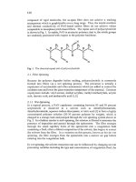
The sp2 orbitals are equivalent, coplanar and oriented at 120" to each other and
form
cs
bonds by overlap with orbitals of neighbouring atoms, as in the molecule
ethene, C,H,, Fig.
1,
A2.
The remaining p orbital on each C atom forms a
7c
bond by overlap with the p orbital from the neighbouring C atom; the bonds
formed between
two
C
atoms
in
this
way are represented as Csp"Csp2, or
simply as C=C.
AI.
ethane
A2,
ethene
A3,
&go
RI,
benzene
B2,
coronene
83,
ovalene
Fig.
1.
Some molecules
with
different
C-C
bonds.
Al,
ethane,
C,H,
(sp');
A2,
ethene,
C,H,
(sp');
A3,
ethyne,
C,H,
(sp');
B1,
benzene,
CJ16
(aromatic);
B2,
coronene,
C,,H,,;
B3,
ovalene,
C,,H,,.
In the third type of hybridisation of the valence electrons
of
carbon,
two
linear
2sp' orbitals are formed leaving
two
unhybridised 2p orbitals. Linear
(T
bonds
are formed by overlap of the
sp
hybrid orbitals with orbitals of neighbouring
atoms, as in the molecule ethyne (acetylene) C2H2, Fig. 1,
A3.
The unhybridised
p orbitals of the carbon atoms overlap to
form
two
n
bonds; the bonds formed
between two C atoms in this way are represented as Csp~Csp, or simply as C=C.
It is also useful to consider the aromatic carbon-carbon bond exemplified by the
prototypical aromatic molecule benzene, C6&. Here, the carbon atoms are
arranged
in
a regular hexagon which is ideal for the formation of strain-free spz
cs
bonds.
A
conventional representation of the benzene molecule as a regular
hexagon
is
in Fig. 1,
B
1. The ground state
n
orbitals in benzene are all bonding
orbitals and are fully occupied and there is a large delocalisation energy that
contributes to the stability of the compound. The aromatic carbon-carbon bond
is denoted as Car~Car. Polynuclear aromatic hydrocarbons consist
of
a number,
n,
of
fused benzene rings; examples are coronene,
C,,H,,,
(n
=
7)
and ovalene,
C,,H,,, (n
=
lo), Fig.
1
B2,
B3,
where delocalisation of
n
electrons extends over
the entire molecule. Note that the C:H atomic ratio in polynuclear aromatic
hydrocarbons increases with increasing
n.
Dehydrogenative condensation
of
polynuclear aromatic compounds
is
a feature of the carbonisation process and
eventually leads to an extended hexagonal network
of
carbon atoms,
as
in
the
basal plane
of
graphite (see Sections 2.2 and
6.1).
4
chronologically the fourth crystalline allotrope
of
carbon. Crystalline Fullerenes
are now commercially-available chemicals and their crystal structures and
properties have been extensively studied. By contrast, convenient methods for
mass
production of pure carbynes have not yet been discovered. Consequently,
carbynes have not been
as
extensively characterised as other forms
of
carbon.
The structures and chemical bonding of these crystalline forms
of
carbon are
reviewed
in
this
section.
2.1
Diamond
Diamond
is
an important commodity as a gemstone and as an industrial material
and there are several excellent monographs on the science and technology of
this
material
[3-51.
Diamond
is
most frequently found in a cubic form in which
each carbon atom is linked to four other carbon atoms by
sp3
0
bonds
in
a
strain-free tetrahedral array, Fig.
2A.
The crystal structure is zinc blende
type
and the C-C bond length is 154 pm. Diamond also exists
in
an hexagonal form
(Lonsdaleite) with a Wurtzite crystal structure and
a
C-C bond length
of
152 pm.
The crystal density
of
both types
of
diamond
is
3.52 g-~rn-~.
A
B
Fig.
2.
The
crystal structures
of:
A,
cubic diamond;
B,
hexagonal graphite
Natural diamonds used for jewellery and for industrial purposes have been
mined for centuries. The principal diamond mining centres are
in
Zaire, Russia,
The Republic of South
Africa,
and Botswana. Synthetic diamonds are made by
dissolving graphite in metals and crystallising diamonds at high pressure (12-15
GPa) and temperatures in the range 1500-2000
K
[6];
see section
3.
More
recently, polycrystalline diamond
films
have been made at low pressures by
5
carbon deposition from hydrocarbon-containing gas mixtures that are rich in
hydrogen
[7];
see section 4.2.
Natural and synthetic diamonds contain various impurities. Nitrogen and boron
are found
as
substitutional impurity atom in the crystal lattice. Diamonds are
classified as Types
I
and
II
with subtypes
[5].
Most natural diamonds are Type
Ia containing up to 0.5% of nitrogen in small aggregates, since this
concentration is considerably in excess
of
the solubility limit for nitrogen in the
diamond lattice. Type
Ib
diamonds are rare in nature, but most synthetic
diamonds produced by the high pressure method are of
this
type. Type
Ib
hamonds contain up to
500
ppm
of
substitutional nitrogen. Type IIa diamonds
are very rare in nature and contain barely detectable amounts of nitrogen. Type
IIb
diamonds are even rarer in nature and are p-type semi-conductors, since the
nitrogen content
is
insufficient to compensate for the substitutional boron
present. Significant quantities
of
hydrogen and oxygen are found in diamonds,
especially at surfaces where they stabilise dangling bonds. Metallic inclusions
are found in diamonds, typically aluminium in natural diamonds and nickel and
iron in synthetic diamonds produced at high temperatures and pressures by
the
catalytic method.
2.2
Graphite
As
a well-established allotrope of carbon the crystal structure
of
graphite
is
fully
documented
[SI.
The graphite crystal was an early subject for application
of
X-
ray diffiaction
[9].
Subsequent studies [e.g., 10,
113
confirmed the well-known
hexagonal crystal structure of graphite. The basis of the crystal structure of
graphite is the graphene plane or carbon layer plane, i.e., an extended hexagonal
array of carbon atom with sp2
G
bonding and delocalised bonding. The
commonest crystal
form
of
graphite
is
hexagonal and consists
of
a stack of layer
planes in the stacking sequence
ABABAB
,
Fig.
2B.
The rhombohedral form of graphite with a stacking sequence
ABCABC
is a
minor component
of
well-crystallised graphites. The proportion of
rhombohedral graphite can be increased substantially (typically from
a
few
percent to
- 20%)
by deformation processes, such as grinding [12]. Conversely,
the proportion
of
rhombohedral graphite can be reduced by high temperature
heat-treatment, showing that the hexagonal form
is
more stable. The density of
both forms
of
graphite is 2.26 g~m-~.
For both
forms
of
graphite the in-plane
C-C
distance is 142 pm,
i.e.,
intermediate between Csp3-Csp3 and Csp*spz bond lengths, 153 and 132 pm
respectively, Table 1. Consideration of the resonance structures between carbon
atoms in the plane
show
that
each C-C bond in the carbon layer plane has about
one third double bond character. Carbon layer planes (of
various
dimensions
6
and with different degrees of perfection) are a very important microstructural
element in most engineering carbons and graphites (see Section
6).
There is a large difference between the in-plane C-C distance, 142 pm, and the
interlayer distance,
335
pm,
in
graphite that results from different types
of
chemical bonding. Within planes the C-C bonds are trigonal sp2 hybrid
(r
bonds
with delocalised
7c
bonds. The large interlayer spacing suggests that the
contribution to interlayer bonding fiom
n:
bond overlap
is
negligible. The usual
assumption
has
been that interlayer potentials are of the
van
der Waals type and
there have been many attempts to calculate interplanar properties starting fiom
Lmard-Jones and Buckingham pair potentials. This work
has
been reviewed in
detail by Kelly [SI who concluded that there is no entirely satisfactory treatment
of interlayer forces
in
graphite. More recent evidence from scanning probe
microscopical images of a graphite surface suggest that there may be some
n:
orbital interaction between planes [13].
Natural graphites occur widely around the world, although the quality of the
ores varies widely. High purity graphite ores with up to 100% carbon contents
are mined in
Sri
Lanka,
lower grade ores which must be concentrated are mined
in Russia, China, Germany, Norway, Korea, Mexico and Austria. Ticonderoga
in the
USA
has been used as a source of high quality natural graphite flakes for
fundamental studies. Principal uses of natural graphites are in the foundry and
steel industries and in the refractory and electrical industries,
Most synthetic graphites used for engineering applications are granular
composites consisting of a filler (usually a coke) and a binder carbon formed
fiom pitch. The graphitic order in most engineering grade synthetic graphites
is
less well-developed
than
in
natural
graphite; see section
6.
Well-graphitised
synthetic graphites are produced by hot-pressing pyrolytic graphite
(HOPG
grade); recently, well-graphitised carbons have been formed by heat-treatment
of
compacted polyimide
films
[
151.
2.3
Carbynes
Carbynes are a form of carbon with chains of carbon atoms formed from
conjugated C(sp')=C(sp') bonds (polyynes):
c-=C
-
C=C
.
.or polycumulene
C(sp2)=C(spz)
.
.
.
double bonds.
From
X-ray
diffraction studies of
short
chain (C,-C,) polyynes
[
161 C=C bond
lengths ranged from 1 19-121 pm while C-C bond lengths ranged fiom 132-138
pm, depending upon the local molecular environment, cf. Table
2.
In the late 1960s El Goresy and Donnay
[
171
discovered a new
form
of carbon
which they called white carbon or Chaoite in a carbon-rich gneiss in the Ries
meteorite crater
in
Bavaria. Chaoite has an hexagonal crystal structure and it
7
was proposed that it consisted of polyyne or polycumulene carbon chains lying
parallel to the hexagonal axis. At about the same time other carbyne
forms
with
hexagonal structures were obtained in Russia
[
18,
191
by dehydropolymerisation
of acetylene: a-carbyne and P-carbyne and by Whittaker and his group
in
the
USA
[20-221
(Carbons VI,
VIII,
and
IX).
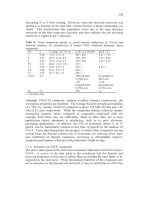
Lattice parameters for some of these
carbyne forms are summarked in Table
3.
Table
3.
Crystal structure
data
for some carbvnes
Carbyne Chaoite a-carbyne P-carbyne carbon
VI
Carbolite
1
Structurea hex. hex. hex. rhomb. hex.
a,
/Pm
895 894 824 923 1 I92
c,
/Pm
1408 1536
768
1224 1062
Densityb
3.43 2.68 3.13 2.90 1.46
a-
hex.
=
hexagonal, rhomb. =rhombohedral; b,
g.crn-’.
Ref.
~71
E1
8,191 [18,191 [20-221 [24]
The hfferent forms of carbynes were assumed to be polytypes with different
numbers of carbon atoms
in
the chains lying parallel to the hexagonal axis and
different packing arrangements of the chains within the crystallite. Heimann
et
al
[23]
proposed that the sizes of the unit cells were determined by the spacing
between
kinks
in extended carbon chains, Fig.
3A.
They were able to correlate
the c, value for the different carbyne forms with assumed numbers of carbon
atoms,
n
(in the range
n
=
6
to
12),
in the linear parts of the chains.
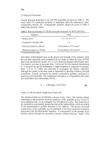
co
A
B
Fig.
3.
A, A
kinked polyyne chain model
for
linear carbynes (after
[23]);
B,
cyclo
C-18
carbyne
[25].
8
Recently, Tanuma and Palnichenko [24] have reported a new form of carbon
which they call 'Carbolite' formed by quenching high temperature carbon
vapour onto a
metal
substrate. Hexagonal Carbolite
I
was formed from an
Ar-
rich gas; a rhombohedral form, Carbolite
II,
was formed from
an
Ar-H,
gas
mixture.
X-ray dimaction peaks were rather broad with coherence lengths
as
low as
20
nm
and this was attributed to rapid quenching. It was proposed that the carbon
atoms are arranged in polyyne chains (n
=
4) along the c-axis. The density
of
Carbolite (1.46 g-~m-~) is lower than values for other carbynes and for diamond
and graphite
-
hence the name
-
and
this
was attributed to a rapid quenching
process.
Molecular orbital calculations indicate that cyclo
C-18
carbyne should be
relatively stable and experimental evidence for cyclocarbynes has been found
[25],
Fig.
3B.
Diederich
et
al
[25]
synthesised a precursor
of
cyclo C-18 and
showed by laser flash heating and time-of flight mass spectrometry that a series
of retro Diels-Alder reactions occurred leading to cyclo
C-
18 as the predominant
fi-agmentation pattern. Diederich has also presented a fascinating review of
possible cyclic all-carbon molecules and other carbon-rich nanometre-sized
carbon networks that may be susceptible to synthesis using organic chemical
techniques [26].
Despite many publications on carbynes, their existence has not been universally
accepted and the literature has been characterised by conflicting claims and
counter claims [e.g., 27-29].
This
is particularly true
of
meteoritic carbynes.
An
interesting account of the nature of elemental carbon
in
interstellar dust
(including diamond, graphite and carbynes) was given by Pillinger
[30].
Reitmeijer
[3
11
has re-interpreted carbyne diffraction data and
has
concluded
that carbynes could be stratified or mixed layer carbons
with
variable
heteroelement content
(H,O,N)
rather
than
a pure carbon allotrope.
In
addition to questions over interpretation
of
difhction data, there are
reservations about the stability of carbynes. Lagow
et
al
[32] note that the
condensation of the compound Li-CaC-Br to
form
carbon chains
is
potentially
explosive. There
is
also the possibility of cross-linking between carbyne chains
and the nature
of
the termination of the carbyne chains is unclear. Eastmond
et
a1
[33]
showed that polyyne compounds
of
the type:
(C2H& Si-(C=C),-Si
(C,H,),
n
=
2
to
16
are stabilised by the bulky silyl end-groups. Lagow
et
a1
[32]
also synthesised
and determined the crystal structure of a polyyne with tertiary butyl end groups:
9
that was stable to
-130°C.
They also found mass spectrometric evidence both
for polyynes of the type
where R
=
phenyl and n
=
16-28,
and
of
carbyne chains with lengths
up
to
C300
after laser ablation of graphite in the presence of
C,N,
and
C,F,.
The
presumption was that these carbynes were stabilised by nitrile
and
trifluoromethyl end caps. For composites of carbynes and alkali metal fluorides
produced by reduction
of ,fluoropolymers
with
alkali metal amalgams,
it
is
argued that the alkali metal matrix suppresses cross-linking
of
the carbyne
chains
[34].
Despite the scepticism
in
some quarters, a large number
of
chemical and
physical methods have been developed for producing carbynoid materials.
These include: dehydropolymerisation
of acetylene, dehydrohalogenation of
polyvinylidene halides and reductive dehalogenation
of
poly(tetrafluoroethy1ene)
and related compounds, condensation
of
carbon
vapour produced by various means, e.g., laser ablation and arc discharge, shock
compression of graphite and other solid forms of carbon
13.51.
At present, no all-
carbon carbynoid material
has
been isolated in large single crystal form and,
consequently, full X-ray structural analyses and bulk property measurements
have not been performed.
(Note.
An
extensive review of carbynes by Russian
workers
[36]
was published after this Section of the Chapter was completed.)
2.4
Fullerenes
Fullerenes are described
in
detail in Chapter
2
and therefore only a brief outline
of their structure is presented here to provide a comparison
with
the other
forms
of carbon. The
C,,
molecule, Buckminsterfullerene, was discovered
in
the mass
spectrum of laser-ablated graphite in
1985 [37]
and crystals
of
C, were
fitst
isolated from soot formed from graphite arc electrodes in 1990
[38].
Although
these events are relatively recent, the
C60
molecule has become one of the most
widely-recognised molecular structures
in
science and
in
1996
the co-
discoverers Curl, Kroto and Smalley were awarded the Nobel prize for
chemistry.
Part
of the appeal of
this
molecule lies in its beautiful icosahedral
symmetry
-
a truncated icosahedron, or a molecular soccer ball, Fig. 4A.
The
C6,,
molecule contains 12 pentagons and
20
hexagons.
This type
of
hexagonal-pentagonal structure closely resembles the geodesic domes
developed by the architect and engineer
R.
Buckminster Fuller,
after
whom the
molecule is named. In the
C,
molecule each carbon atom is bonded to three