Carbon Materials for Advanced Technologies Episode 2 ppt
Bạn đang xem bản rút gọn của tài liệu. Xem và tải ngay bản đầy đủ của tài liệu tại đây (1.02 MB, 40 trang )
20
A
B
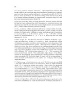
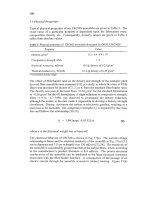
Fig.
9.
A,
Model
for
the
apex
of
a
carbon
nanocone
with
a
cone angle
of
19.2"
[94];
E,
polyhedral
and
spherical
forms
of
a
multiwall
carbon particle formed
from
C,, C,
and
c,
1981.
Ugarte has shown that faceted carbon particles with structures similar to
graphitised carbon black are converted to spherical carbon shell structures under
intense electron beam irradiation
[96-981.
These have been called carbon onions
or 'Buckyonions'. The shells have external diameters up to
-30
nm
and hollow
centres with diameters similar to that of the
C,,
molecule. Ugarte has suggested
that the concentric carbon shells are formed about a central
C,
molecule.
Theoretical calculations
of
the stability of
a
concentric duplet formed by
C,,
about
C,
yield a stabilisation energy of
14
MeV per
C
atom and an optimal
interlayer spacing of
352
pm, close
to
the value for graphite
[99].
Other
calculations on the concentric structure formed by
CH0
about
CZa
show that a
spherical conformation of the
two
layers
is
more stable than the analogous
polyhedral duplet
[98].
Fig.
9B
shows a model for a triple wall carbon particle
in spherical and polyhedral forms constructed
from
C6,,
Ca0,
and
C,,,
[98].
6
Engineering
Carbons
6.
I
Introduction
There are many applications for diamonds and related materials, e.g., diamond-
llke carbon
films,
and there are potential applications for Fullerenes and carbon
nanotubes that have not yet been realised. However, the great majority of
engineering carbons, including most of those described in this book, have
graphitic microstructures or disordered graphitic microstructures.
Also,
most
engineering carbon materials are derived
from
organic precursors by heat-
treatment
in
inert atmospheres (carbonisation).
A
selection of technically-
21
important carbons obtained
from
solid, liquid
and
gaseous organic precursors is
presented
in
Table
5.
Table
5.
Precursors
for
engineering carbons
Primary
Secondag
1
Example
products
precitrsor
precursor
Hydrocarbon
gases
Petroleum
petroleum pitch
mesophase pitch
Coals
coal chars
coal tar pitch
mesophase
pitch
Polymers polyacrylonitrile
phenolic
and
furan resins
pol yimides
Biomassb
pyrocarbons, carbon blacks,
vapour
grown
carbon
fibres, matrix carbonn
delayed coke, calcined coke
needle coke, carbon fibers, binder and
matrix
carbon"
mesocarbon microbeads, carbon fibers
semi-coke, calcined coke
activated carbons
premium cokes, carbon
fibers,
binder and matrix
carbons'
mesocarbon microbeads, carbon fibers
PAN-based carbon fibers
glassy carbons, binder and matrix carbons"
graphite films and monoliths
activated carbons
a.
precursor
for
binder
in
polygranular carbons
and
graphites,
precursor
for
matrix
in
carbon-carbon
composites;
b,
especially wood and nutshells
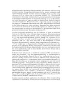
During carbonisation the organic precursor
is
thermally degraded by heat-
treatment at temperatures in the range
-450-1000
"C to form products that
undergo either condensation or volatilisation reactions, the competition between
these processes determining the carbon yield. Fig.
10
provides examples
of
the
chemical processes that occur during carbonisation of the model precursor
acenaphthylene
[
1001,
Some of the volatilised products produced during
carbonisation may be recovered to produce useful secondary precursors for
carbons. For example, petroleum pitch and coal tar pitch are secondary
precursors that
are
produced during carbonisation
of
petroleum and coal, Table
5.
Carbons formed after heating up to
-1000
"C
(pnmary
carbonisation) are
low-temperature carbons. They are usually disordered without any evidence for
three-dimensional graphitic order and they may also retain significant
concentrations of heteroelements, especially
0,
H,
and
S,
and
mineral matter.
It is beyond the scope of this chapter to review structure and bonding
in
each
class of engineering carbons listed in Table
5.
Instead, a generic description of
microstructure and bonding
in
these materials will be attempted. The evolution
in understanding
of
the structure of engineering carbons and graphites has
foIlowed the initial application
of
X-ray diffraction and subsequent application
22
of
electron and neutron diffraction, and high resolution electron microscopy,
supplemented by a wide range
of
other analytical techniques.
further
condensation
-
u
Fig.
10.
Mechanism
of
carbonisation
of
acenaphthylene
[
1001.
I,
acenaphthylene; 11,
polyacenaphthylene; 111, biacenaphthylidene; IV, fluorocyclene;
V,
dinaphthylenebutadiene;
VI,
decacyclene; VII, zethrene. Reprinted
from
[
1001
courtesy
of
Marcel Dekker Inc.
6.2
X-ray studies
of
engineering carbons
In the
1930s
Hoffman and Wilm
[loll
found only
(hk0)
graphte reflections in
an x-ray diffraction study of a carbon black. The absence of graphitic
(hkl)
reflections led them to propose a structure consisting
of
graphitic carbon layer
23
planes in parallel array but without any three-dimensional order. They also
noted from the position of the [002] line that the interlayer spacing,
d,
was
greater than that for the graphite crystal (d
=
0.3354
nm).
This early concept
of
the microstructure of an engineering carbon
forms
the basis of the more refined
models that have been developed in subsequent years. Biscoe and Warren
[lo21
coined the term 'turbostratic' to describe a parallel stack of carbon layer planes
with random translation about the a-axis and rotation about the c-axis.
Turbostratic carbon
is
therefore without three-dimensional order and the
turbostratic value of the interlayer spacing d, 0.344
nm,
is greater than that for
graphite. The dimensions of the turbostratic stack in the a and c
crystallographic directions are characterised from the pronounced X-ray line
broadening by the width
and
height,
La
and
L,
respectively, as well as the
interlayer spacing, d. Values found by Hoffmann and Wilm [101] for a range of
technical carbons ranged from
La
=
2.1-12
nm
and
L,
=
0.9-18
nm;
the latter
values imply stacks containing from
3
to about
50
layer planes. The broadening
of X-ray lines is also influenced by imperfections in the carbon layer planes
so
that the dimensions of stacks, particularly the width, may be larger than is
indicated by
La
and
L,
values. High resolution electron microscopic studies lend
some support to this view (see Section
6.4).
A
notable advance was made by Franklin
[
103
J
in
an
X-ray diffraction study of
polymer chars. She found that for a low-temperature
PVDC
char that
65%
was
in the
form
of turbostratic carbon and the remainder was an unspecified form
of
disordered carbon. Subsequently,
[
1041
FrankIin classified low temperature
carbons into graphitising carbons which develop three-dimensional graphtic
order on heat-treatment above 2000
"C
and non-graphitising carbons which do
not. The structure
of
graphitising carbons was envisaged an array of turbostratic
carbon units that were oriented in near-parallel (pre-graphitic) array; non-
graphitising carbons contained turbostratic units
in
random array that were
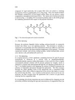
cross-linked by disorganised carbon, Fig. 11. Franklin's classification is now
recognised as oversimplified, since there
is
a near-continuum
from
graphitising
to non- graphitising microstructures. Nevertheless, the concepts
of
graphitising
and non-graphitising carbons are useful and they have been retained.
Amorphous carbon films of the type a-C and a-C:H produced by physical or
chemical vapour deposition from the gas phase contain varying amounts of
sp2
and sp3 bonded carbon atoms, see section 4.1. The possibility of both sp2 and
sp3 bonded atoms in carbons produced by carbonisation
of
organic precursors
has been considered by a number
of
workers. The presence of sp3 bonded
carbon, particularly in the disorganised carbon that links the carbon layer planes
in non-graphitising carbons, seems reasonable in principle. In an X-ray
study
No&
and co-workers
[
105
]
obtained radial distribution hnctions for a glassy
carbon and proposed that some sp3 carbon atoms were present. However, a later
high resolution X-ray study
of
a
high temperature glassy carbon by Wignall and
24
Pings [106], and a neutron diffraction study by Mildner and Carpenter
[107],
both concluded that there is
no
clear evidence for sp3 carbon and that the rachal
distribution functions can be satisfactorily indexed to a hexagonal mays of
carbon atoms. A similar conclusion was reached in a recent neutron diffraction
study of activated carbons by Gardner
et
al
[
1081.
A
B
Fig.
11.
Schematic
models
for the structure
oE
A,
graphitising carbons,
and
B,
non-
graphitising carbons
[104].
6.3
The
carbonaceous
mesophase
It is now
known
that the development of graphitising carbons depends upon the
formation of a liquid crystal phase called the carbonaceous mesophase during a
fluid stage
in
carbonisation.
The
mesophase appears initially as small, optically
anisotropic spheres growing out of an optically isotropic fluid pitch. The
mesophase spheres contain polynuclear aromatic hydrocarbons (molecular
weight
- 2000)
in parallel arrays [l09], Figs. 12A, 12Ba).
As
carbonisation
proceeds, higher molecular weight hydrocarbons are formed by condensation
and these are incorporated into the mesophase. With growth and coalescence of
the mesophase, there
is
eventually a phase inversion when the coalesced
mesophase becomes the dominant phase, Fig. 12Bb). Condensation and
polymerisation proceed as the carbonisation temperature
is
raised until
eventually the material solidifies into a semi-coke, Fig. 12Bc). The relics of the
coalesced mesophase in the semi-coke have complex anisotropic structures that
contains
disclinations that can be used to deduce their molecular orientation
[110]. The essential point
is
that the coalesced mesophase generates a pre-
graphitic structure that can be developed into graphite on high temperature heat-
treatment. The carbonisation of polyacenaphthylene, Fig.
10,
is an example
of
a
process that involves the formation of mesophase. By contrast, the
carbonisation of precursors of non-graphitising carbons does not involve the
formation
of
mesophase. Either, the non-graphitising precursor is extensively
cross-linked, as in the case of phenolic resins, or cross-linking reactions occur in
the early stages of carbonisation.
25
Fig.
12.
A,
Schematic representation
of
parallel arrays
of
polynuclear aromatic
hydrocarbon molecules in a mesophase sphere.
B,
a)
isolated
mesophase spheres in
an
isotropic fluid
pitch
matrix;
b)
coalescence
of
mesophase;
c)
structure
of
semi-coke
after
phase inversion and solidification.
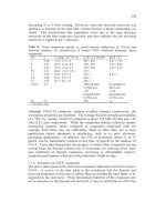
Carbon layer planes in low temperature carbons are highly defective and they
have heteroelements bound to their edges. Heat treatment of graphitising
carbons brings about
an
improvement in microstructural order, elimination
of
heteroelements and eventually the development of a three-dimensional graphite
crystal structure. Abundant X-ray studies of a wide range of graphitising
carbons, Fig. 13, show that the stack width,
La,
for graphitising carbons
increases almost exponentially with heat-treatment temperature,
HTT,
from
-5
nm
at HTT -1500 "C to -35-65
nm
at
HTT
=
2800 "C; the stack thickness,
L,,
increases in a similar fashion from -2-6
nm
at
HTT
-1400 "C to -15-60
nm
at
HTT
=
3000
"C
[112]. At the same time the interlayer spacing d decreases from
the turbostratic value, 0.344
nm,
towards the value for graphte, 0.335
nm.
By
contrast, the stack dimensions of non-graphitising carbons increase only slightly
with HTT accompanied by small decreases in interlayer spacings
[
104, 1 131.
26
30
Fig.
13.
Increase
in
stack width parameter,
La,
with
heat treatment temperature,
HTT,
for
some graphitising cokes, [Adapted
from
1121.
6.4.
Electron microscopical studies
of
engineering carbons
The microstructural model for disordered carbons has been greatly elaborated
following the application of high resolution transmission electron microscopy.
The early work by Ban
[
1
141 and Jenkins
et a1
[
1 151 lead to the development of
the ribbon model for glassy carbon, Fig. 14, which envisages the non-graphitic
structure as a network of twisted and folded carbon layer planes. Interestingly,
this microstructural model for carbons was perhaps the first to depart from the
flat graphite layer model and introduce concepts of curvature that can now be
rationalised using microstructural elements borrowed from Fullerenes and
nanotubes. However, the Jenkins model is essentially intuitive and later
workers
[
1
161 have cautioned against the use
of
such simplistic readings
of
electron microscopical images.
Perhaps the most elaborate and extensive electron microscopical studies of
carbonaceous materials were carried out by Agnes Oberlin and her group
[
1 161
who showed that a great deal of microstructural information on carbons can be
obtained using a combination of selected area diffraction and dark field and
light field imaging. For all carbons, Oberlin defines a basic structural unit, BSU,
as a parallel stack of two to four layer planes each containing less than 10-20
aromatic rings. A related concept is local molecular ordering,
LMO,
which
consists of an array of BSU with a near-common orientation, Fig. 15. In non-
27
graphitising carbons there is a high degree
of
misorientation
of
BSU
so
that
LMO
is small or non-existent, whereas
in
graphitising carbons the
misorientation between adjacent
BSU
is small and consequently there
is
extensive
LMO
extenlng to the order
of
microns.
-
L.&
Fig.
14.
The
ribbon model for the microstructure
of
a glassy carbon
[
1
151.
Fig.
15.
A
schematic model illustrating the concepts
of
basic structural unit,
BSU,
and
local molecular ordering,
LMO
[e.g.,
1161.
28
The Oberlin group have elaborated the mechanism of graphitisation as shown
in
Fig. 16. Earlier work
on
graphitisation mechanisms has been reviewed on
several occasions [117-1191. In stage 1, up to
HTT
=
1000
"C,
the carbons
contains flat BSU with a high degree of misorientation.
Between
1000
and
1500
"C
(stage
2)
the BSU grow &cker and columnar arrays of BSU (like
stacks
of
coins) develop with misoriented
BSU
trapped between them.
In
stage
3,
between
HTT
=
1500
to
2000
"C
the misorientation between the columns of
BSU decreases,
so
that extensive, but distorted, carbon layer planes can form by
coalescence
of
adjacent BSU. The fmal stage, above
HTI'
=
2000
"C,
involves
the annealing out
of
defects within the distorted carbon layer planes,
so
that
perfect flat carbon layer planes are produced that allow the formation and
growth
of
graphite crystallites.
-
@
flat
layers
f
STAGES
44
torted
layers
rted
columns
Fig.
16.
The
mechanism
of
graphitisation (Reprinted from
[
1161
by
courtesy of Marcel
Dekker Inc.
7
Concluding Remarks
The majority of engineering carbon materials have more-or-less disordered
microstructures that are based on that
of
graphite and in which, therefore, sp2
carbon bonding
is
dominant. The degree of graphitic order varies widely from
very low values for glassy carbons derived from polymer resins
[
1
131 to highly
graphitic microstructures, e.g.,
in
HOPG
[14].
Engineering carbons are also
29
manufactured
in
an astounding range
of
physical
forms:
powders,
granules,
beads,
films,
foams, fibers, textiles, composites, and monoliths, and
in
sizes that
range from sub-micron carbon aerogels to arc furnace electrodes with
dimensions of several metres. The steady development
of
graphtic carbon
materials over many years has been complemented by recent developments
in
amorphous carbon
films
with mixed sp' and sp3 bonding and, especially rapid
developments
in
CVD
diamond
films
with sp3 carbon bonds. However, the
discoveries
of
Fullerenes and related materials represent the most exciting new
developments in carbon science. Indeed, these discoveries have resulted
in
a
paradigm shift
in
om
perception
of
chemical bonding and microstructure in
carbon materials and have helped to stimulate further advances
in
various areas
of carbon science and technology that are discussed elsewhere
in
this book.
8
Acknowledgements
I thank Marcel Dekker Inc. for permission to reprint Figures
10
and 16.
9
References
1.
2.
3.
4.
5.
6.
7.
8.
9.
10.
11.
12.
13.
14.
15.
Atkins, P.W.,
Physical Chemistry,
5"
Edition, Oxford 'university Press, Oxford,
1994, Chapter 14.
Handbook
of
Chemistry
and
Physics,
74th edition, ed.,
D.R.
Lide,
CRC
Press,
London., 1994, pp 9-2 to 9-5.
Davies,
G.,
Diamond,
Hilger, Bristol, 1984.
Wilks, J.
and
Wilks,
E.,
Properties
and
Applications ofDiamonds,
Buttenvorth-
Heinemann, Oxford, 199
1.
The Properties
of
Natural and Svnthetic Diamond,
ed.
J.E.
Field, Academic
Press, London, 1992.
Bundy,
F.P., Hall, H.T., Strong, H.M. and Wenthof,
R.H.,
Nature (London),
1956,
176,
51.
Spytsin,
B.V., Boulov, L.L. and Deraguin,
B.V.,
J.
Cryst.
Growth, 198 1,52,2 19.
Kelly, B.T.
Physics
of
Graphite,
Applied Science Publishers, London, 198 1.
Hull,
A.W.,
Phys. Rev.,
1917, 10,661.
Bernal,
J.D.,
Proc.
Roy.
Soc.,
1924,
A106,
749.
Hassel,
0.
and
Mark,
H.,
Z.
Phys.,
1924,25,3 17.
Bacon,
G.,
Acta
Cyst.,
1958,3, 320.
Tominek,
D.,
Louie,
S.G.,
Mamin, H.J., Abraham, D.W., Thomson, R.E.,
Gam,
E.
and Clarke,
J.,
Phys. Rev. B, 1987,35, 7790.
Moore, A.W., In
Chemistry
andPhysics
ofcarbon,
Vol.
17, ed.,
P.L.
Walker Jr.
and
P.A.
Thrower, M. Dekker,
New
York, 198 1,
pp
233-286 .
Hishiyama,
Y.,
Yasuda,
S.,
Yoshida,
A.
and Inagaki, M., J. Mater. Sci., 1988, 23,
3272.
16.
17.
18.
19.
20.
21.
22.
23.
24.
25.
26.
27.
28.
29.
30.
31.
32.
33.
34.
35.
36.
37.
38.
39.
40.
41.
42.
43.
Coles, B.F., Hitchcock, P.B. and Walton, D.R.M., J. Chem. SOC. Dalton, 1975, 5,
442.
El Goresy,
A.
and Donnay,
G.
,
Science, 1968, 161,363.
Kasatochkin, V.I., Sladkov,
A.M.,
Kudryatsev, Yu.P., Popov,
N.M.
and Korshak,
V.V.,
Dokl.
Chem., 1967,177,1031.
Kasatochkin, V.I., Korshak, V.V., Kudryatsev, Yu.
P.,
Sladkov,
A.M.
and
Sterenberg, L.E., Carbon, 1973, 11,70.
Whittaker, A.G. and Wolten,
G.M.
,
Science, 1972, 178, 54.
Whittaker, A.G., Carbon, 1979, 17,21.
Whittakcr,
A.G.,
Neudorffer,
M.E.
and Watts, E.J., Carbon, 1983,21,597.
Heimann, R.B., Kleiman,
J.
and Salansky,
N.M.
,
Carbon, 1984, 22, 147.
Tanuma,
S.I.
and Palnichenko,
A.,
J.
Mater. Res., 1995,10, 1 120.
Diederich,
F.,
Rubin,
Y.,
Knobler, C.B., Whetten, R.L., Schriver, K.E., Houk,
K.N. and Li, Y., Science, 1989,245, 1088.
Diederich,
F.,
Science, 1994, 369, 199.
Smith, P.P.K.
and
Busek, P.R., Science, 1982,216,984.
Whittaker,
A.G.,
Science, 1985,229,485.
Smith, P.P.K. and Busek,
P.R.,
Science, 1985,229,486.
Pillinger, C.T., Phil.
Trans.
Roy. SOC. London
A,
1993, 343,73.
Reitmeijer,
F.J.M.,
Meteoritics, 1993,
28,
242.
Lagow, R.J., Kampa, J.L., Wei, H-C., Battle, S.L., Genge,
J.W.,
Laude, D.A.,
Harper, C.J., Bau, R., Stevens, R.C., Haw, J.F., and Munson,
E.,
Science, 1995,
267,362.
Eastmond. R., Johnston, T.R. and Walton, D.R.M., Tetrahedron, 1972, 28,4601.
Jansta. J. and Dousek, F.P., Carbon, 1980, 18,433.
Kavan, L. and Kastner, J., Carbon, 1994,32, 1533.
Kudryatsev, Yu.P., Evsyukov,
S.,
Guseva, M., Babaev,
V.
and Khvostov, V., In
Chemistry
and
Physics
of
Carbon,
ed.
PA.
Thrower, Vol. 25, M. Dekker, New
York, 1997, pp 1-69.
Kroto,
H.W.,
Heath, J.R., OBrien, S.C., Curl, R.F. and Smalley, R.E., Nature
(London) 1985,318,162.
Kratschmer,
W.,
Lamb, L.D., Fostiropoulos, K., and Huffman,
D.R.,
Nature
(London) 1990,347,354.
Hawkins, J.M., Mayer,A., Lewis,
T.A.,
Loren,
S.
and Hollander, F.J., Science,
1991,252,312.
Kikuchi,
K.,
Susuki,
S.,
Saito, K., Shiramura,
H.,
Ikemoto,
I.,
Icheba,
Y.,
Zhakidov,
A.,
Ugawa,
A.,
Imaeda,
K.,
Inokuchi,
H.
and Yashuki,
K.,
Physica C,
1991,185,415.
Saito,
Y., Susuki, N., Shinohara,
H.,
Hayashi,
T.
and Tomita, M.,
Ultramicroscopy, 1992, 41,
1.
Taylor,
R.,
Hare,
J.P.,
Abdul-Sada, A.K. and Kroto, H.W.,
J.
Chem.
SOC.
Commun., 1990, 1423.
Yannoni, C.S., Johnson,
R.D.,
Meijer,
G.,
Bethune, D.S. and Salem, J.R.,
J.
Phys. Chem., 1991,95, 9.
31
44.
45.
46.
47.
48.
49.
50.
51.
52.
53.
54.
55.
56.
57.
58.
59.
60.
61.
62.
63.
64.
65.
66.
67.
Tycko, R., Haddon, R.C., Dabbagh, G., Glarum, S.H., Douglas, D.C. and
Mujsce, A.M.,
J.
Phys. Chem., 199 1, 95,
5
18.
David, W.I.F., fiberson, R.M., Matthewman, J.C., Prassides, K., Dennis,
T.J.S.,
Hare, J.P., Kroto, H.W., Taylor, R. and Walton, D.R.M., Nature (London), 1991,
353, 147.
David, W.I.F., Ibberson, R.M. and Matsuo,
T.,
Proc. Roy. SOC. (London)
A
442,
1993, 129.
Prassides, K.,
Kroto,
H.W., Taylor, R., Walton, D.R.M., David, W.I.F.,
Tomkinson,
J.,
Haddon, R.C., Rosseinsky, M.J. and Muphy, D.W., Carbon,
1992,30, 1277.
Kroto,
H.W., Nature (London) 1987,329, 529.
Schmalz,
T.G.,
Seitz, W.A., Klein, D.J. and Hite, G.E. J. Amer. Chem. SOC.,
1988,110, 113.
Diederich F. and Whetten R.L. Acc. Chem. Res., 1992,
25,
119.
Saito,
S.,
Sawada, S.I., Hamada,
N.
and Oshiyama, A., Mater. Sci. Eng., 1993,
B19, 105.
Smalley, R.E., Acc. Chem. Res. 1992, 25, 98.
Holmes-Parker, D., Chatterjee,
K.,
Wurz, P., Lykke, K.R., Pellin, M.J., Stock,
L.M. and Hemminger, J.C., Carbon, 1992, 30, 1167.
Verheijen, M.A., Meekes, H., Meijer, G., Bennema, P., de Boer, J.L., van
Smaalen,
S.,
Tendeloo, G.V., Amelinckx,
S.,
Muto,
S.
and van Landuyt, J.
Chem. Phys., 1992, 166, 287.
Li,
Y.Z.,
Patrin, J.C., Chandler, M., Weaver, J.H., Kikuchi,
K.
and Achiba,
Y.,
Phys. Rev.
B,
1993,47, 10867.
Wang, X.D., Hashimme, T., Shinohara, H., Saito,
Y.,
Nishina,
Y.
and Sakurai,
T.,
Phys. Rev.
B,
1993, 47, 15923.
Armbruster, J.F., Romberg, H.A., Schweiss, P., Adelman, P., Knupfer,
M.,
Fink,
J.,
Michel, R.H., Rockenberger, J., Hennrich, F., Schreiber, H. and Kappes,
M.M.,
Z.
Phys. B, 1994,95,469.
Dresselhaus,
M.S.,
Dresselhaus, G. and Eklund, P.C.,
Science
of
Fullerenes and
Carbon Nanotubes,
1996, Academic Press, San Diego.
Bundy, F.P., J. Geophys. Res., 1980, 85,6930.
Gustafson, P., Carbon, 1986, 24, 169.
Bundy, F.P.,?hysica, 1989, A156, 169.
Bundy, F.P., Bassett, W.A., Weather, M.S., Hemley, R.J., Mao, H.K. and
Goncharov, A.F., Carbon, 1996,34, 141.
Deraguin, B.V., Fedoseev, D.V., Varnin, V.P. and Vnukov, S.P., Nature
(London) 1977,269,398.
Whittaker, A.G., Science, 1978, 200, 763.
Young, D.A. and Grover, R., In
Shock Waves in Condensed Matter,
ed.
S.C.
Schmidt and
N.C.
Holmes, North Holland, Amsterdam, 1988, p. 13
1.
Yin, M.T. and Cohen, M.L., Phys. Rev. Lett., 1983, 50,2006.
Biswas, R., Martin, R.M., Needs,
R.J.
and Nielsen, O.H., Phys. Rev.
B.,
1984,
30, 3210.
32
68.
69.
70.
71.
72.
73.
74.
75.
76.
77.
78.
79.
80.
81.
82.
83.
84.
85.
86.
87.
88.
89.
90.
91.
92.
93.
94.
95.
96.
97.
98.
99.
Biswas, R., Martin, R.M., Needs, R.J. and Nielson, O.H., Phys. Rev. B., 1987,
Sekine, T., Carbon, 1993,31,227.
Bachmann, P.K., In
Ullman
s
Encyclopaedia
of
Industrial Chemistry,
1996, Vol.
Robertson, J., Adv. Phys., 1986,35, 317.
McLintock,
I.S.
and Orr, J.C., In
Chemistry and Physics ofcarbon,
Vol. 11, ed.
P.L. Walker Jr.,
M.
Dekker, New York, 1973.
Anderson, D.A., Phil. Mag., 1977,35, 17.
Weissmantel, C., Bewilogua, K., Breuer, K., Dietrich, D., Ebersach,
U.,
Erler,
H.J.,
Rau, B. and Reissen,
G.,
Thin Solid Films, 1982,96,
3
1.
Spytsin, B.V., Bouilov,
L.L.
and Derjaguin,
B.V.,
J.
Cryst. Growth, 1981,
52,
219.
Matsumoto,
S.,
Sato,
Y.,
Kamo,
M.
and Setaka,
N.,
Jap. J. Appl. Phys., 1982, 21,
Kamo,
M.,
Sato, Y., Matsumoto,
S.,
Setaka,
N.,
J. Cryst.
Growth,
1983,62,642.
Y. Sat0 and M.
Kamo,
In
The Properties
of
Natural and Synthetic Diamond,
ed.
J.E. Field, Academic Press, London, 1992, pp. 423-469.
Bachmann, P.K. and van Enckevort,
W.,
Diamond Relat. Mater.,
1992,
1,
1021.
Bachmm, P.K., Leers, D and Lydtin,
H.,
Diamond Rclat Mater, 1991,
1,
1.
Prijaya, N.A., Angus,
J.C.
and Bachmann, P.K., Diamond Relat Mater., 1993,3,
129.
Frenklach, M. and Wang,
H.,
Phys. Rev. B., 1991,43, 1520.
Roy, R., Dewan,
H.S.
and Ravindranathan,
P.,
J.
Mater. Chem., 1993,3, 685.
Roy,
R.,
Cherian, K.A., Cheng, J.P., Badzian,
A.,
Langlade, C., Dewan, 13. and
Drawl,
W.,
Knnov. Mater. Res., 1336, 1, 65.
Ijima,
S.,
Nature (London), 1991,354, 56.
Endo,
N.,
Takeuchi, K., Igarashi,
S.,
Kobori,
K.,
Shiraishi, M. and Kroto,
H.W.,
J. Phys. Chem. Solid,
1993,
54, 1841.
Ajayan, P.M. and Ijima,
S.,
Nature (London), 1992,358,23.
Dresselhaus, M.S., Nature (London), 1992, 358, 195.
Dresselhaus, M.S., Dresselhaus,
G.
and Saito, R., Phys. Rev. B., 1992,45,6234.
Hamada,
N.,
Sawada, S.I. and Oshiyama, A., Phys. Rev. Lett., 1992,
68,
1579.
White,
C.T.,
Robertson, D.H. and Mintmire,
J.W.,
Phys. Rev.
B.,
1993,47,5485.
Carbon
Nanotubes: Preparation and Properties,
ed.
T.W.
Ebbesen, 1997, CRC
Press, Boca Raton.
Balaban, A.T., Klein, D.J. and Liu,
X.,
Carbon, 1994,32, 357.
Sattler,
K., Carbon, 1995,33,915.
Ijirna,
S.,
Ichihashi, T. and Ando,
Y.,
Nature (London), 1992,356,776.
Ugarte,
D., Nature (London), 1992,359,707.
Ugarte, D., Chem. Phys. Lett., 1993,
207,
473.
Ugarte, D., Carbon, 1995, 33, 989.
Yosida,
Y.,
Fullerene Sci. Tech., 1993,
1,
55.
35,9559.
A26,
pp 720-725.
L183-185.
33
100.
101.
102.
103.
104.
105.
106.
107.
108.
109.
110.
111.
112.
113.
114.
115.
116.
117.
118.
119.
Fitzer,
E.,
Mueller,
K.
and Schaeffer, W., In
Chemistry and Physics of Carbon,
Vol. 7, ed., P.L. Walker Jr., M. Dekker, New York, 1971, p. 237.
Hoffman,
U.
and Wilm, D.,
Z.
Elektrochem., 1936,42, 504.
Biscoe,
J.
and Warren,
BE.,
J.
Appl. Phys., 1942,
13,
364.
Franklin,
R.E.,
Acta. Cryst., 1950,3, 107.
Franklin,
R.E.,
Proc. Roy. Soc., 1951,
A209,
196.
Noda,
T.,
Inagaki,
M.
and Yamada, Y.J., J. Noncryst. Solid, 1969, 1,285.
Wignall,
G.D.
and Pings, C.J., Carbon, 1974, 12, 5
1.
Mildner, D.F.R. and Carpenter, J.M.,
J.
Noncryst. Solid, 1982,
47,
391.
Gardner, MA., Dore, J.C., North, A.N., Cazorla-Amoros, D., Salinas-Martinez
de Lecea,
C.
and
Bellissent Funel, M-C., Carbon, 1996,34, 857.
Brooks, J.D. and Taylor,
G.H.,
in
Chemistry and Physics of Carbon,
ed. P.L.
Walker, Jr., Vol. 4, 1968, M. Dekker, New York, p. 243.
White, J.L. and Zimmer, J.E. in
Surface and Defect Properties
of
Solids,
ed.
M.W. Roberts and J.M. Thomas, Vol.
5,
1976, Chemical Society, London, p 16.
Jackson, W.M. and Conley, W.T., J. Appl. Polym. Sci., 1964,
8,
2163.
Hutcheon, J.M.,
In
Modern Aspects
of
Graphite Technolog),,
ed. L.C.F.
Blackman, 1970, Academic Press, London,
pp
2-48.
Jenkins,
G.M. and Kawamura,
K.,
Polymeric Carbons: Carbon Fibre, Glass, and
Char,
Cambridge University Press, Cambridge, 1976.
Ban,
L.L.,
In
Surface and Defect Properties
of
Solids,
ed. M.W. Roberts and J.M.
Thomas,
Vol.
1,
1972, Chemical Society, London, p. 54.
Jenkins, G.M., Kawamura,
K.
and Ban, L.L., Proc. Roy. SOC. (London), 1972.
A327,501.
Oberlin,
A.,
In
Chemistry and Physics
of
Carbon,
Vol. 22, 1989, ed. P.A.
Thrower,
M.
Dekker, New York,
pp
1-144.
Maire, J. and Mering,
J.,
In
Chemistry and
Physics
of
Carbon,
Vol.
6,
1970,
ed.
P.L.
Walker
Jr.,
M. Dekker, New York,
p.
125.
Fischbach,
D.,
In
Chenzistr?, and Physics
of
Carbon,
Vol. 7, 1971, ed.
P.L.
Walker Jr.,
M.
Dekker, New York, p. 1.
Pacault,
A.,
In
Chemistry and Physics
of
Carbon,
Vol. 7, 1971, ed. P.L. Walker
Jr.,
M.
Dekker, New York,
p.
107.
35
CHAPTER
2
Fullerenes and Nanotubes
M.S.
DRESSELHAUS
Department
of
Electrical Engineering and Computer Science
and Department
of
Physics
Mussachusetts Institute
of
Technology,
Cambridge, Massachusetts 02139, USA
P.C.
EKLUND
Department
of
Physics and Astronomy and
Center for Applied Energy Research
University of Kentucky, Lexington,
KK
40506,
USA
G.
DRESSELHAUS
Francis Bitter Magnet Laboratory
Massachusetts Institute
of
Technology,
Cambridge, Massachusetts, 02139, USA
The structure-property relations
of
fullerenes, fullerene-derived solids, and car-
bon nanotubes are reviewed
in
the context
of
advanced technologies for carbon-
based materials. The synthesis, structure and electronic properties
of
fullerene
solids are then considered, and modiJications to their structure and properties
through doping with various charge transfer agents are reviewed. Brief comments
are included
on
potential applications
of
this unique,family
of
new mateviuls.
1
Introduction
Fullerenes and carbon nanotubes are unique, respectively, in the larger family
of carbon-based materials as interrelated prototypes for zero-dimensional
quantum dots and one-dimensional quantum wires. The fullerene molecule is
the fundamental building block of the crystalline phase, and through doping
and chemical reactions, forms the basis of a large family of materials, many
having especially interesting properties. Likewise, carbon nanotubes, which
are capped at each end by half of a fullerene, have aroused great interest in the
research community because of their exotic electrical and mechanical proper-
ties. The unique properties of fullerenes and carbon nanotubes described in
this chapter are also expected to be of interest for practical applications.
In 1985, the existence of a stable molecule or cluster with
60
carbon atoms
(designated as 0) was established experimentally by mass spectrographic
analysis [l], and it was conjectured that the
CSO
cluster was a molecule with
icosahedral symmetry. The name
of
“fullerene”
was
given to the family of
closed cage carbon molecules by Kroto and Smalley
[l]
because of their
resemblance to the geodesic domes designed and built by R. Buckminster
Fuller
[2].
The name “buckminsterfullerene” or simply “buckyball” was given
specifically to the
c60
molecule.
In
the early gas phase work, the fullerene
molecules were produced by the laser vaporization of carbon from a graphite
target in a pulsed jet of helium
[1,
31.
In the fall of 1990,
a
new crystalline form of carbon, based on
c60,
was
synthesized for the first time by Kratschmer, Huffman and co-workers
[4].
Their discovery
of
a simple method using a carbon arc for preparing gram
quantities of
c60
and
C70
represented a major advance to the field because
previous synthesis techniques could only supply trace quantities
[
1,
51.
The
availability of large quantities of
c60
and
C70
fullerenes provided a great
stimulus to this research field. It was soon found
[6,
7‘J
that the intercalation
of alkali metals into solid
c60
to
a
stoichiometry M&o (where
M
=
K,
Rb)
could greatly modify the electronic properties
of
the host fullerene lattice,
yielding not only metallic conduction, but also relatively high transition
temperature
(18
5
T,
5
40K)
superconductors
[8].
The discovery of relatively
high temperature superconductivity [9,
lo]
in these compounds (see
52.6.2)
further spurred research activity in this field of (260-related materials.
Regarding
a
historical perspective on carbon nanotubes, very small diameter
(less than
10
nm) carbon filaments were observed in the 1970’s through syn-
thesis of vapor grown carbon fibers prepared by the decomposition of benzene
at 1100°C in the presence of Fe catalyst particles of -10 nm diameter [ll, 121.
However,
no
detailed systematic studies of such very thin filaments were re-
ported in these early years, and it was not until Iijima’s observation of carbon
nanotubes by high resolution transmission electron microscopy
(HRTEM)
that the carbon nanotube field was seriously launched.
A
direct stimulus
to the systematic study of carbon filaments of very small diameters came
from the discovery of fullerenes by Kroto, Smalley, and coworkers
[l].
The
realization that the terminations of the carbon nanotubes were fullerene-like
caps or hemispheres explained why the smallest diameter carbon nanotube
observed would be the same as the diameter of the
c60
molecule, though
theoretical predictions suggest that nanotubes are more stable than fullerenes
of the same radius
[13].
The Iijima observation heralded the entry of many
scientists into the field of carbon nanotubes, stimulated especially by the un-
37
usual quantum effects predicted for their electronic properties. Independently,
Russian workers also reported discovery of carbon nanotubes and nanotube
bundles, but generally having much smaller aspect (length to diameter) ratios
[14,
151.
This article reviews the structure and properties of fullerenes, fullerene-based
materials and carbon iianotubes in the context of carbon materials for ad-
vanced technologies.
2
Fullerenes and Fullerene-based Solids
2.1
Synthesis
Fullerene molecules are usually synthesized using an ac discharge between
graphite electrodes in approximately
200
torr of He gas. The heat generated
between the electrodes evaporates carbon to form soot and fullerenes. Typ-
ically the fullerene-containing soot, has up to
-15%
fullerenes:
c60
(-13%)
and
C70
(-2%)).
The fullerenes are extracted from the soot and separated
according to their mass, size or shape, using techniques such as liquid chro-
matography, and a solvent such as toluene. A variety of techniques and
experimental conditions have been employed in the synthesis and separation
(purification) of fullerenes, depending on the desired mass distribution, mass
purity, and cost.
Property measurements of fullerenes are made either on powder samples, films
or single crystals. Microcrystalline
c60
powder containing small amounts of
residual solvent is obtained by vacuum evaporation of the solvent from the
solution used in the extraction and separation steps. Pristine
c60
films used
for property measurements are typically deposited onto a variety of substrates
(e.g.,
a clean silicon
(100)
surface to achieve lattice matching between the
crystalline
c60
and the substrate) by sublimation of the C60 powder in an inert
atmosphere
(e.g.,
Ar) or in vacuum. Single crystals can be grown either fron?
solution using solvents such as CS2 and toluene, or by vacuum sublimation
[16,
17,
IS].
The sublimation method yields solvent-free crystals, and is the
method of choice.
Doping is used
to
modify the properties of fullerenes, particularly their
electronic properties. Although fullerene solids (called fullerites) can be
doped in three ways (endohedrally, substitutionally, and exohedrally), the
exohedral doping has been of primary interest. Endohedral doping denotes
the addition of a rare earth,
an
alkaline earth or an alkali metal ion into the
interior of the
c60
molecule. This step in the synthesis must occur while
the molecule is being formed since dopant atoms cannot penetrate the fully
formed fullerene cage. As an example of the notation used
to
denote an
endohedral fullerene, La@C60 denotes one endohedral lanthanum in C60, or
Y2@C82
denotes
two Y
atoms inside
a
C8z
fullerene
[19].
Thus far, only
small quantities of endohedrally-doped fullerenes have been prepared and
only limited investigations of endohedrally-doped crystalline materials have
been reported but steady progress is being made both in synthesis and in
properties measurements
[20].
A second doping method is the substitution of an impurity atom with
a
dif-
ferent valence state for
a
carbon atom on the surface of a fullerene molecule.
Because of the small carbon-carbon distance in fullerenes
(1.444,
the only
species that can be expected to substitute for a carbon atom in the cage is
boron. There has also been some discussion of the possibility of nitrogen
doping, which might be facilitated by the curvature of the fullerene shell.
However, substitutional doping has not been widely used in practice
@1].
The most common method of doping fullerene solids is exohedral doping
(also called intercalation if the solid
C~O
host is formed first). In this case, the
dopant
(e.g,
an alkali metal or
an
alkaline earth,
M)
is diffused into the in-
terstitial positions between adjacent molecules (exohedral locations). Charge
transfer takes place between the
M
atoms and the fullerene molecules,
so
that
the
M
atoms become positively charged ions and the fullerene molecules be-
come negatively charged with the additional electrons delocalized in
T
orbitals
over the surface of the molecule. With exohedral doping, the conductivity of
fullerene solids can be increased by many orders
of
magnitude
f22].
Dop-
ing fullerenes with acceptors has been considerably more difficult than with
donors because of the high electron affinity of
CSO
[23,24],
though examples
of stable compounds with acceptor-type dopants have been synthesized
[7].
Among the alkali metals, Li, Nay
K,
Rb, and
Cs
and their alloys have
been used as exohedral dopants for
CSO
[25,
261,
with one electron typically
transferred per alkali metal dopant. Although the metal atom dausion
rates appear to be considerably lower, some success has also been achieved
with the intercalation
of
alkaline earth dopants, such
as
Ca, Sr, and Ba
[27,28,29],
where two electrons per metal atom
M
are transferred to the
c60
molecules for low concentrations of metal atoms, and less than two electrons
per alkaline earth ion for high metal atom concentrations. Since the alkaline
earth ions are smaller than the corresponding alkali metals in the same row
of
the periodic table, the crystal structures formed with alkaline earth doping
are often different from those for the alkali metal dopants. Except for the
alkali metal and alkaline earth intercalation compounds, few intercalation
compounds have been investigated for their physical properties.
Fullerene chemistry leading to novel fullerenelike molecules with new chem-
ical groups that are radially attached has become
a
very active research field,
largely because of the uniqueness of the
c60
molecule and the variety of
chemical reactions that appear to be possible
[30,
311.
Many new fullerene-
based molecules have already been synthesized and characterized chemically,
39
Fig.
1.
(a)
The
icosahedral
CSO
molecule
(soccer
ball).
@)
The
C70
molecule
as
a
rugby-bail-shaped
molecule.
Two
C80
isomers:
(c)
the
CSO
molecule
as
an extended
rugby-ball-shaped
molecule.
(d)
The
CSO molecule
as
an
icosahedron.
and
a
few of these molecules have been incorporated into crystal structures.
The chemical additions are made at or across the double
(C=C)
bonds located
at the fusion of two hexagons (Fig.
1).
Attention has also been given to
functional groups which lead to water-soluble products.
2.2
Structural
Properties
Since the structure and properties of fullerene solids are strongly dependent
on the structure and properties of the constituent fullerene molecules, we
first review the structure of the molecules, which is followed by
a
review
of
the structure of the molecular solids formed from
c60,
Cy0
and higher mass
fullerenes. and finally the structure of
c60
crystals.
2.2.1
Structure of molecular
c60
The
60
carbon atoms in
c60
are
in
potential minima located at the vertices
of a regular truncated icosahedron. Every carbon site on the
c60
molecule
is
equivalent to every other site [see Fig. l(a)], consistent with a single sharp
line in the
NMR
spectrum
[32,
331.
All the C-atoms reside at a distance
of
-3.55A
from the center of the molecule. The average nearest-neighbor
carbon-carbon
(C-C)
distance
ac-c
in
c60
(1.44A)
is
almost identical to
that in graphite
(1.42A).
Each carbon atom in
c60
(and also in graphite)
is trigonally bonded to three nearest-neighbor carbon atoms, and in some
sense, the
C60
molecule can be considered as a “rolled-up” graphene sheet
(a
single layer of crystalline graphite). The regular truncated icosahedron has
20
40
hexagonal faces and 12 additional pentagonal faces to form a closed shell, in
keeping with Euler’s theorem, which states that a closed surface consisting of
hexagons and pentagons has exactly
12
pentagons and an arbitrary number of
hexagons [21]. Pentagons or heptagons are required to form curved surfaces;
the flat graphene sheet contains only hexagonal rings.
The symmetry operations of the icosahedral
CSO
molecule consist of the
identity operation, 12 five-fold axes through the centers
of
the pentagonal
faces,
20
three-fold axes through the centers of the hexagonal faces, and 15
two-fold axes through centers of the edges joining
two
hexagons. Each of the
60
rotational symmetry operations can be compounded with the inversion
operation, resulting in
120
symmetry operations
in
the icosahedral point
group
1,
[34].
Molecules with
1h
symmetry,
c60
being the most prominent
example, have the highest degree of symmetry or possess the largest number
of symmetry operations of any known molecule.
From Euler’s theorem on the structure of general polyhedra, it follows that the
smallest geometrically possible fullerene is
CZO
which would form a regular
dodecahedron with 12 pentagonal faces. It is, however, considered energeti-
cally unfavorable for two pentagons to be adjacent to each other (referred to
as the isolated pentagon rule) since two adjacent pentagons would lead to a
very high local curvature and therefore high strain on the fullerene molecule.
Therefore,
CZO
is relatively unstable. Since the addition of a single hexagon
adds two carbon atoms, all fullerenes must have an even number of carbon
atoms, in agreement with the observed mass spectra for fullerenes
[3].
Although each carbon atom in
CSO
is
equivalent to every other carbon
atom, the three bonds emanating from each atom [see Fig. l(a)] are not
completely equivalent. Each of the four valence electrons of the carbon
atoms are engaged in covalent bonds,
so
that two of the three bonds (along
the pentagon edges) are electron-poor single bonds, and one (between two
hexagons) is an electron-rich double bond. The structure of
c60
is stabilized
by introducing a small distortion of the bond lengths to form the KekulC
structure of alternating single and double bonds around the hexagonal face,
with the single bonds increased from the average bond length of 1.44A to
1.46A,
while the double bond lengths are decreased to
1.40A
[35,
361.
The
KekulC structure gives rise to
a
truncated icosahedron with
I,
symmetry, with
the same point group symmetry as the regular truncated icosahedron where
all bond lengths are identical. Since each carbon atom on
a
CSO
molecule has
its bonding requirements fully satisfied, solid
c60
is
expected to form a van
der Waals bonded solid with a semiconducting energy gap in the electronic
density of states comparable to the molecular HOMO-LUMO gap
(-1.9
eV,
ie.,
the gap between the highest occupied molecular orbital and the lowest
unoccupied molecular orbital).
41
2.2.2
Structure of C~O and higher fullerenes
In the synthesis of C60, largermolecular weight fullerenes C,
(n
>
60) are also
formed, by far the most abundant being Go. However, sufficient quantities
of
c76,
c78,
and Cg4 have also been isolated to be studied in some detail.
c70
has been found to exhibit a rugby ball shape [37], and its form can
be envisioned either by adding
a
ring of 10 carbon atoms or a belt of
5
hexagons around the equatorial plane of the
c60
molecule oriented normally
to one of the five-fold axes
[see
Fig.
le)].
In contrast to the C~O molecule
with
Ih
symmetry, the C70 molecule has the lower symmetry
Dsh
which is
a subgroup of
I
(lacking inversion symmetry).
Careful chromatographic
separations [7, 381 have shown that higher fullerenes can form isomers,
i.
e.,
a given number
n
of carbon atoms C, can form molecules with different
geometrical structures [37,39].
As
an illustration, CSO might be formed in the
shape of an elongated rugby ball prepared by adding two rows of
5
hexagons
normal to
a
five-fold axis of
c60
at the equator [see Fig. 1(c)]; an icosahedral
form
of
Cgo can also be specified
as
shown
in
Fig. l(d). Another example of a
family of fullerene isomers is
c78
which has
5
distinct isomers, none of which
are icosahedral [40].
2.2.3 Crystalline
c60
In the solid state, the
c60
molecules crystallize into a cubic structure with a
lattice constant of 14.17&
a
nearest neighbor CSO-CSO distance of
10.02A
[41], and
a
mass density of 1.72 g/cm3 (corresponding to 1.44
x102'
c60
molecules/cm3). Taking advantage of both the nearly spherical shape and
the weak intermolecular bonding, the C60 molecules
at
thermal energies cor-
responding to room temperature, each rotate rapidly about their equilibrium
lattice position with three degrees of rotational freedom. In this rapidly rotat-
ing state, the molecules are equivalent and are arranged on a face centered
cubic (fcc) lattice (space group
0;
or
Fmh)
with one
c60
molecule per
primitive fcc unit cell, or 4 molecules per conventional simple cubic unit cell
[see Fig. 2(a)]
[43,
44,
451. Relative to the other allotropic forms of carbon,
solid
c60
is relatively compressible, with an isothermal volume compressibility
of
6.9
x
cm2/dyn
[35],
which is about two times greater than graphite,
which
is
highly compressible only in the c-axis direction.
Below a temperature of
Tol
N
260
K,
the
c60
molecules completely lose
two of their three degrees of rotational freedom, and the residual degree
of
freedom is a ratcheting rotational motion for each
of
the four molecules within
the unit cell about a different
(111)
axis [43, 45, 46, 471. The structure
of
solid
c60
below
To1
becomes simple cubic (space group
2';
or
Pa3
with
a
lattice constant
a0
=
14.17A
and four
c60
molecules per unit cell, as the four
oriented molecules within the
fcc
structure become inequivalent [see Fig. 2(a)]
[43, 451. Supporting evidence for the phase transition at
To1
N
260
K
is
42
C60
(fcc)
MCGO
M~Go
M3C60
(a)
bet
(b)
fcc
(c)
fcc
(a)
fcc
c60
MbC60
M6CbO
MGCGO
(e)
bcc
(f)
bct
(g)
brc
(11)
fer
Fig.
2.
Structures for the solid (a) fcc
c60,
(b) fcc
MC60,
(c) fcc
Mac60
(d) fcc
M3C60,
(e) hypothetical bcc
c60,
(f)
bct
M4C60,
and two structures for
M6C60:
(g) bcc
M6C60
for
(M=
K,
Rb,
Cs),
and (h) fcc
M6C60
which is appropriate for
M
=
Na, using
the notation of Ref
[42].
The notation fcc, bcc, and bct refer, respectively, to face
centered cubic, body centered cubic, and body centered tetragonal structures. The
large spheres denote
c60
molecules and the small spheres denote alkali metal ions. For
fcc
M3C60,
which has four
c60
molecules per cubic unit cell, the
M
atoms can either be
on octahedral or tetrahedral symmetry sites. Undoped solid
c60
also exhibits the fcc
crystal structure, but in this case all tetrahedral and octahedral sites are unoccupied.
For
(g)
bcc
M6C60
all the
M
atoms are on distorted tetrahedral sites. For
(f)
bct
M4C60,
the dopant
is
also found on distorted tetrahedral sites. For (c) pertaining to
small alkali metal ions such as Na, only the tetrahedral sites are occupied. For
(h)
we
see that four Na ions can occupy an octahedral site of this fcc lattice.
43
provided by many property measurements [21].
As
the temperature is lowered
below
260
K,
further ordering of the
C60
molecules occurs, whereby adjacent
e60
molecules develop correlated orientations.
In this low temperature structure, the relative orientation of adjacent
molecules is stabilized by aligning an electron-rich double bond on one
molecule opposite the electron-poor pentagonal face of an adjacent molecule
to achieve
a
minimum in the orientational potential energy. Another structure
with only slightly higher energy places the electron-rich double bond of one
(260
molecule opposite an electron-poor hexagonal face. This orientation can
be achieved from the lower energy orientation described above by rotation
of the Cso molecule by
60"
around a
(111)
axis
[4q.
As
the temperature
T
is
lowered below 260
K,
the probability of occupying the lower energy
configuration increases
1461.
The mechanism by which partial orientational
alignment is achieved is by the ratcheting motion of the CSO molecules
around the
(111)
axes as they execute their hindered rotational motion. The
ratcheting motion begins below the 260
K
phase transition and continues
down to low temperatures. Since the icosahedral Cso molecules lack four-fold
symmetry axes, it is not possible to achieve full molecular alignment of
CG0
molecules in a cubic crystal structure with 4-fold axes. The residual
orientational disorder that results is called merohedral disorder, which
gives rise to an important scattering process for the transport properties of
fullerene solids.
2.2.4 Crystalline
C70
and higher fullerenes
The crystal structure of C70 is more complex than that of crystalline
c60
[48,
49,
50,
51,
521, and has been studied in much detail. Less detailed
structural information is available for the higher mass fullerenes. At high
temperature
(T
>>
340
K),
the fcc phase
(a
=
1Ei.OlA)
of C70 with freely
rotating molecules is most stable, but since the ideal hexagonal close packed
@cp) phase with
e/u
=
1.63
is almost equally stable, fcc crystals
Of
C70 tend to
be severely twinned and show many stacking faults.
A
transition to another
hcp phase with
a
=
b
=
lO.llA
and a larger
c/u
ratio of 1.82 occurs at
-340
K.
This larger
e/a
ratio is associated with the orientation of the
C70
molecules along their long axis, as the free molecular rotation (about any axis)
that
is
prevalent in the higher temperature phase evolves into a free rotation
about the 5-fold axis of the C70 molecule
[49,
521.
As
the temperature is
further lowered to -280
K,
the free rotation about the e-axis also becomes
frozen, resulting in a monoclinic structure with the high symmetry axis along
the e-axis of the hcp structure.
The higher mass fullerenes (C76,
CS4),
with multiple isomers of different
shapes, also crystallize in the fcc structure at room temperature, with an fcc
lattice constant which is approximately proportional to
n1I2,
where
n
is the
number of carbon atoms in the fullerene [53].
44
Fig.
3.
Crystal structure of the cornpoundCso(S8)zCSz projected normal to the a-axis.
Large circles denote CSO, small circles denote sulfur, black balls denote carbon.
In
this
structure, the C~O-C~O distance is nearly
11
8,
and the diameter
of
the C~O molecule
has been reduced relative to
the
other atoms for clarity
[54].
2.2.5 Doped
c60
crystals
Several stable crystalline phases for exohedrally doped (or intercalated) solid
c60
have been identified. Most widely studied are the crystalline phases
formed by intercalation of alkali metals, though some structural reports
have been given for fullerene-derived crystals doped with alkaline earths [27].
In this review, we focus attention primarily on doped
c60
materials where
charge transfer occurs. However, clathrate
c60
compounds involving organic
spacer molecules, where there is no significant charge transfer, also show some
interesting crystal structures such as that for
c6O(sS)Cs2
(see Fig.
3)
[54]. As
more (&-based compounds are synthesized, we can expect further studies of
their crystalline structure and properties.
When
c60
is doped with the alkali metals
(M
=
Na,
K,
Rb,
Cs),
stable
crystalline phases are formed for the compositions
MlCso,
M3C60,
M4C60,
and [21,42,55,56]. The phase diagram for
KzC60,
illustrated in Fig. 4
[57], shows stability regions for the rock salt phase of
K1C60,
the fcc phase of
K3C60,
the bct phase of
KsCso,
and the bcc phase of
I(6c60.
The phase
diagram for
KzC60,
stable regions are illustrated in the cross-hatched areas of
this binary phase diagram [57], and the location of the guest species relative to
the fullerenes is shown
in
Fig. 2. At lower temperatures (not shown in Fig. 4),
the
MlC60
phase is transformed into a polymer chain structure with short
c60-c60
bonds between molecules along the chain direction.
For the alkali metal doped
c60
compounds, charge transfer of one electron
per
M
atom to the
c60
molecule occurs, resulting in
M+
ions at the tetrahedral
and/or octahedral symmetry interstices of the cubic
c60
host structure. For
the composition
M3C60,
the resulting metallic crystal has basically the fcc
structure (see Fig. 2). Within this structure the alkali metal ions can sit
on
either tetragonal symmetry (1/4,1/4,1/4) sites, which are twice as numerous as
the octahedral (1/2,0,0) sites (referenced to a simple cubic coordinate system).
The electron-poor alkali metal ions tend to lie adjacent to a
C=C
double