Carbon Materials for Advanced Technologies Episode 13 ppsx
Bạn đang xem bản rút gọn của tài liệu. Xem và tải ngay bản đầy đủ của tài liệu tại đây (1023.4 KB, 40 trang )
460
dependent on temperature and
time.
This
effect
has
been accounted for through the
concept of equivalent temperature. If
two
irrahations are performed at hfferent
levels of fast neutron flux,
4,
and
a2,
identical damage will be caused if the
two
irradiation temperatures are related by
where k is Boltzmann's constant and
A
is an activation energy determined
experimentally. Usually, one of the flux levels would pertain to a standard position
in a materials test reactor.
As
discussed by Burchell [58] experimental evidence
suggests that
flux
level or rate effects are significant only at low to moderate
irradiation temperatures
(<400"C).
3.2
Dimensional changes
A
principal result of carbon atom displacements is crystallite dimensional change.
Interstitial defects will cause crystallite
growth
perpendicular to the layer planes (c-
axis direction), whereas coalescence of vacancies will cause a shmkage parallel
to the layer plane (a-axis direction). The damage mechanism and associated
dimensional changes are illustrated in Fig. 6. Radiation-induced dimensional
changes can be very large, exceedmg
60%
in well-ordered graphite materials.
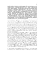
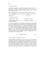
Pryrolytic graphite has frequently been used to study the neutron irradiation-
induced dimensional changes of the graphite crystallite [57,59]. Price
[60]
conducted such a study. Figure 7 shows Price's data for crystallite shmkage in the
a-direction for neutron doses up to
-
12 dpa. Price's samples were graphitized at
a temperature of 2200-3300°C prior to being irradiated at 1300-1500°C. The a-
axis shrinkage increased linearly
with
dose for all of the samples, but the
magnitude of the shrinkage at any given dose decreased with increasing
graphitization temperature. Similar trends were noted for the c-axis expansion.
The effect of graphitization temperature on irrabtion-induced dimensional change
accumulation can be attributed to thermally induced improvements in crystal
perfection. Higher graphitization temperatures reduce the initial number of lattice
defect sites which are available to trap irradiation-induced vacancies, and thus
reduce the rate of damage accumulation.
Polygranular graphites possess a polycrystalline structure, usually with significant
texture resulting from the method of forming during manufacture. Consequently,
structural and dimensional changes in polygranular graphites are a function of the
crystallite dmensional changes and the graphite's texture. In polygranular
graphite, thermal shrinkage cracks formed during manufacture and that are
preferentially aligned in the crystallographic a-direction, initially accommodate the
c-direction expansion,
so
mainly a-direction contraction will be observed. The
46
1
graphite thus undergoes
a
net volume shrinkage. With increasing neutron dose
(displacements), the incompatibility
of
crystallite dimensional changes leads to the
generation of new porosity oriented parallel to
the
basal planes, and the volume
shrinkage rate falls, eventually reaching
zero.
The graphite then begins to swell at
an increasing rate
with
increasing neutron dose because
of
the combined effect
of
c-axis growth and new porosity generation. The graphite
thus
undergoes a volume
change "turnaround" into net growth which continues until the generation
of
cracks
and pores
in
the graphite, due to differential crystal strain, eventually causes
total
disintegration
of
the graphite.
COLLAPSW
VACANCY
VACANCY
EXPANSION
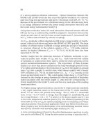
Fig.
6.
Radiation damage
in
graphite showing the induced crystal dimensional strains.
Impinging fast neutrons displace carbon atoms from their equilibrium lattice positions,
producing an interstitial and vacancy.
The
coalescence of vacancies causes contraction
in
the
a-direction, whereas interstitials may coalesce to form dislocation loops (essentially new
graphite planes) causing c-direction expansion.
Fig.
7.
High-temperature neutron irradiation a-axis shrinkage behavior
of
pyrolytic graphite
showing the
effects
of
graphitization temperature
on
the
magnitude of the dimensional
changes
[60].
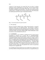
462
Irradiation-induced dimensional damage data for GraphNOL
N3M
are shown in
Fig.
8.
N3M
is a molded graphite and thus the filler coke particles are
preferentially aligned
in
the radial direction. Consequently, the crystallographic a-
direction is predominantly aligned in the radial direction (perpendicular to forming)
direction. Therefore, the a-direction irradiation-induced shmkage
is
more apparent
in the radial direction,
as
indicated by the radial data (both
600
and
875°C)
in Fig.
8.
1-0-
6009:
RADIAL
I
-3.5
I
I I
I
I
I I
0
5
10
(5
20
25
30
35
40
FLUENCE
(dpa)
Fig. 8.
Neutron irradiation induced dimensional changes
for
GraphNOL
N3M
graphite
irradiated a
600
or
875
"C
[6
11.
Note that the radial dimensional changes exceed the axial
changes due
to
textural
effects.
A
general theory of dimensional change
in
graphite due to Simmons
[62]
has been
extended by Brocklehurst and Kelly
[
171.
A
detailed account of the treatment of
dimensional changes in graphite can be found in Kelly and Burchell's analysis of
H-451
graphite irradiation behavior
[63].
3.3
Stored energy
The irradiation induced displacement processes previously described can cause an
excess of energy (associated with the vacancylinterstitial pairs) in the graphite
crystallites. The release of
this
stored energy (or Wigner energy, after the physicist
who
fist
postulated its existence
[21])
was historically the first problem of
radiation damage in graphite to manifest itself. When
an
interstitial carbon atom
and lattice vacancy recombine, their excess energy is given up.
If sufficient
damage has accumulated in the graphite, the release
of
this
stored energy can result
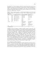
in a rapid rise in temperature. Stored energy accumulation was found to be
463
0.6
particularly problematic
in
the early (air-cooled) graphite moderated reactors,
which operated at relatively low temperatures. Figure
9
shows the rate of release
of
stored energy with temperature, as
a
function of temperature, for graphite
samples irradiated at
30°C
to three different doses
(0.01,
0.1,
and 0.6 dpa)
in
the
Hanford
K
reactor. The release curves are characterized by a peak occurring at
-200°C which
is
associated with the recombination of single interstitials and
vacancies. With increasing neutron dose, the
200°C
peak becomes broader and the
maximum release rate
is
reduced. The release rate exceeds the specific heat, thus
under adiabatic conditions the graphite would rise sharply in temperature.
For
ambient temperature irradiations it
was found that the stored energy could attain
values up to
2720
J/g, which if released adiabatically would cause a temperature
rise
of
some 1300°C
[7].
The uncontrolled release of stored energy from graphite,
causing a
sharp
rise
in
core temperature, was
of
great concern to the operators
of
the early air-cooled (low-temperature) graphite reactors.
In
order to limit the total
amount
of
stored energy it became necessary to periodically anneal the graphite.
The core temperature was raised sufficiently, by nuclear heating or inserted
electrical heaters, to "trigger" the release of stored energy from the graphite. The
release then self-propagated slowly through the core, raising the graphite moderator
temperature and thus partially annealing the graphite core.
It
was during such a
reactor anneal that the Windscale
(U.K.)
Reactor accident occurred in
1957
[24].
I
I
I
I
I
I
I
I
EXWSURES
IN Mwd/At
&
dpabpprox)
-
i-
a3
9
'O
02
u)
0.
i
0
300
400
500
100
200
ANNEALING TEMPERATURE
0
Fig.
9.
Stored
energy
release curves for
CSF
graphite irradiated
at
-30°C
in the Hanford
K
reactor cooled test hole
[64].
Note, the rate (with temperature) of stored
energy
release
(JKgK)
exceeds
the specific
heat
and thus
under
adiabatic conditions self sustained heating
will occur.
464
The accumulation of stored energy in a graphite
is
both dose and irradiation
temperature dependent. With increasingly higher irradiation temperatures the total
amount of stored energy and
its
peak rate of release diminish, such that above an
irradiation temperature of
-300°C
stored energy ceases to be a problem. Excellent
accounts of stored energy in graphite can be found elsewhere
[7,62,64,65].
3.4
Eflects
on
mechanical and physical properties
The physical properties
of
carbon and graphite materials are drastically altered by
irradiation damage. For example, low dose irradiation
(<<1
dpa) can increase the
strength of a graphite by up to
80%
while simultaneously reducing the thermal
conductivity by more
than
an
order of magnitude. Graphite is a phonon conductor
of
heat. The temperature dependence of thermal conductivity
is
shown in Fig. 10
for various pyrolytic graphites in the unirradiated condition. The substantial
improvements in thermal conductivity caused by thermal annealing, andor
compression annealing, are attributable to increased crystal perfection and size
of
the regions of coherent ordering (crystallites). This minimizes the extent of
phonon-defect scattering and results in a larger phonon mean free path. With
increasing temperature the dominant phonon interaction becomes phonon-phonon
scattering (Umklapp processes). Therefore, the observed reduction of thermal
conductivity with increasing temperature, and the convergence of the curves in Fig.
10,
are attributed to the dominant effect of Umklapp
scattering
in reducing phonon
mean free path.
1200
-a-
COMPRESSION
ANNEALED
E
\
-*-
ANNEALED
3000%
u
3
900
E
700
800
>
3
0
J
(r
w
I-
2
600
500
1400
I
300
200
II
Ill
I
II
0
200
400
600
800
10oO12oO4~
4W
4800
TEMPERATURE
("c)
Fig.
10.
The
temperature
dependence
of
thermal
conductivity
for
pyrolytic graphite in three
diffment conditions
[66].
The reduction
of
thermal
conductivity
with
increasing temperature
is attributed
to
increasing Umklapp scattering
of
phonons.
465
The mechanism of thermal conductivity and the degradation of thermal
conductivity have been extensively reviewed
[57-591.
The increase of thermal
resistance due to irradiation damage has been ascribed to the formation of
[67]:
(i)
submicroscopic interstitial clusters, containing
4
f
2
carbon atoms; (ii) vacant
lattice sites, existing as singles, pairs, or small groups; and
(iii)
vacancy loops,
which exist in the graphite crystal basal plane and are too small to have collapsed
parallel
to
the hexagonal axis. The contributions of collapsed lines of vacant lattice
sites and interstitial loops
to
the increased thermal resistance is negligible. The
reduction in thermal conductivity due to irradiation damage is temperature and
dose sensitive.
At
any irradiation temperature, the decreasing thermal conductivity
will reach a "saturation limit." This limit
is
not exceeded until the graphite
undergoes gross structural changes at very high doses. The "saturated" value of
conductivity will be attained more rapidly, and will be lower, at lower irradiation
temperatures. The effect of radiation damage on the thermal conductivity of
carbon materials
is
discussed extensively here by Snead in his chapter on "Fusion
Reactor Applications."
In
graphites, the neutron irradiation-induced degradation
of thermal conductivity can be very large, particularly at low temperatures. Bell
et
al.
[65] report that the room temperature thermal conductivity of PGA graphite
(the
Magnox
core graphite)
is
reduced
by
more
than
a factor of
70
when irradiated
at
155°C
to
a dose
of
-0.6 dpa. At
an
irradiation temperature
of
355°C
the thermal
conductivity
of
PGA was reduced by less than a factor of 10 at doses twice that
obtained at 155°C. Above
600°C
the reduction of thermal conductivity
is
less
significant. For example, Kelly
[7]
reports the degradation of
PGA
at a high
temperature. At
an
irradiation temperature
of
600°C and a dose
of
-
13
dpa, the
thermal conductivity was only degraded by a factor of
-6.
Moreover, at
a
irradiation temperatures of
920°C
and 1150°C the degradation was minimal (less
than a factor of
4
at
-7
dpa).
The thermal expansion of polygranular graphites is controlled by the thermal
closure of aligned internal porosity. Irradiation-induced changes in the pore
structure (see earlier discussion
of
structural changes) can therefore be expected
to
modify the thermal expansion behavior of carbon materials. The behavior of
GraphNOL
N3M
(Fig. 11)
is
typical of many fiie-textured graphites [61], which
undergo
an
initial increase
in
the coefficient of thermal expansion followed by a
steady reduction to
a
value less than half the unirradiated value of
-
5
x
1
0-6
O
C'.
Similar behavior is reported by Kelly
[7]
for the AGR moderator graphite (grade
IM1-24).
The electrical resistivity
of
graphite will
also
be affected by radiation damage. The
mean free path of the conduction electron in an unirradiated graphte is relatively
large, being limited only by crystallite boundary scattering. Neutron irradiation
introduces: (i) scattering centers, which reduce charge carrier mobility; (ii) electron
traps, which decreases the charge carrier density; and (iii) additional
spin
466
resonance. The net effect
of
these changes is to increase the electrical resistivity
on irrahation, initially very rapidly, with little or no subsequent change
to
relatively high fluence
[58,61].
A subsequent decrease at very high neutron doses
may be attributed to structural degradation.
Fig.
11.
Neutron irradiation-induced changes in the coefficient of thermal expansion
of
GraphNOL N3M at irradiation temperatures
of
600
and
875°C [61].
The mechanical properties of graphites are substantially altered by radiation
damage.
In
the unirradiated condition, polygranular graphites behave in a brittle
fashion and fail at relatively low strains. The stress-strain curve is non-hear, and
the fracture process occurs via the formation of sub-critical cracks, which coalesce
to produce a critical flaw
[9,10].
When graphites are irradiated the stress-strain
curves become more linear, the strain
to
failure is reduced, and the strength and
elastic modulus increased.
As
shown in Fig.
12,
there is a rapid rise in strength
attributed to dislocation pinning at irradiation-induced lattice defect sites. This
effect has largely saturated at doses
>1
dpa. Above
-
1
dpa a more gradual increase
in
strength occm due to structural changes within the graphite.
For
polygranular
graphites the dose at which the maximum strength is attained loosely corresponds
with the volume change turnaround dose, indicating the importance of pore
generation in controlling the high-dose strength behavior.
The
strain
behavior of polygranular graphite subjected to an externally applied load
is largely controlled by shear of the component crystallites. As with strength,
irradiation-induced changes in Young’s modulus are the combined result of in-
crystallite effects, due to low fluence dislocation pinning, and superimposed
467
structural changes external to the crystallite. The effects of these
two
mechanisms
are generally considered separable, and related by:
(EEo)irradiated
=
(EEo)pinnmg
(E’Eo)structwe
(2)
Where
E&
is the ratio of the irradiated
to
unirradiated elastic modulus. The
dislocation pinning contribution to the modulus change is due to relatively mobile
small defects and
is
thermally annealable at
-2000°C.
Figure
13
shows the
irradiation-induced elastic modulus changes for GraphNOL
N3M.
The low dose
change due to dislocation pinning (dashed line) saturates at a dose
4
dpa.
1
60
rn
6W’C
60
I
10
20
FLUENCE
(dpa)
Pig.
12.
Neutron irradiation-induced strength changes for GraphNOL N3M
temperatures
of
600
and
875°C
[61].
iotr
I
I
I
I
I
5
40
45
20
25
30
0.
FLUENCE
(dpd
at irradiation
Fig.
13.
Neutron irradiation-induced Young‘s modulus changes for GraphNOL
N3M
at
irradiation temperatures
of
600
and
875°C
[61].
468
The elastic modulus and strength are related by a Griffith theory type relationship.
GE
strength,
u
=
(-)1'2
ITC
(3)
where
G
is the fracture toughness
or
strain energy release rate (J/m2)>,
E
is the
elastic modulus (Pa), and c
is
the
flaw
size
(m).
Thus, irradiation-induced changes
in
u
and
E
(in the absence of changes
in
[G/c]) should follow
u
Eln.
High dose
data reported recently by
Ishiyama
et
al.
[68] show significant deviation from this
relationship for grade
IG-110
graphite, indicating that changes
in
G
and or c must
occur.
3.5
Radiation
creep
Graphite
will
creep under neutron irradiation and stress at temperatures where
thermal creep is normally negligible. The phenomenon
of
irrahation creep has
been widely studied because of its significance to the operation of graphite
moderated fission reactors. Indeed, if irradiation induced stresses in graphite
moderators could not relax via radiation creep, rapid core disintegration would
result. The observed creep strain has traditionally been separated into a primary
reversible component
(e,)
and a secondary irreversible component
(e2),
both
proportional to stress and
to
the appropriate unirradiated elastic compliance
(inverse modulus)
[69].
The total irradiation-induced creep strain
(€3
is thus:
Ec
=
61
f
E2
(4)
or,
Eo
=
(O/Eo)[l
-
exp(-by)]
+
(K/Eo)ay
(5)
where
E,,
the unirradiated Young's Modulus, b is a constant,
y
is the neutron dose,
and
K
is the irradiation creep coefficient. Kelly
[7]
has reported that values of
-4
x
for
b
and
0.23
x
lo-*'
for
K
apply to
U.K.
data
taken
over
a range of
irradiation temperatures
(300-650°C).
At high fluences
Eq.
(5)
must be modified
to account for structural changes occurring in the graphite:
where
-
is
the initial secondary creep rate and
S(y)
is the "structure factor"
normally deduced
from
Young's Modulus changes ascribed to structural effects
l"d:.1,
469
(i.e.,
S(y)
=
(E/E,)
where
E
is the Young's Modulus at fluence
y
and
E
,is the
Young's modulus after the initial increase due to dislocation pinning).
Oh
et
al.
[70] have reported the creep coeEcient of
IG-
1 10 graphite and shown
it to be reasonably linear with temperatures over the range 300-1400°C at low to
moderate fluences
(<
2
dpa). Kennedy
et
aZ.
[71] have reported the irradiation
creep rate of a German graphite in tension and compression for creep strains
in
excess of 3.5%. Their data show the creep rate decreasing at higher fluences
(>6
dpa) where the creep strain exceeds
-
1%.
Kelly and Burchell [72] attempted to
rationalize the disparity between Kennedy
et aZ.'s
data indicating a reducing creep
rate and the more commonly reported constant creep rate. They concluded that the
reported reduction in creep rate was not a true reduction, but rather an artifact
of
changes
in
the properties in the stressed sample which modified their dimensional
change under irradiation compared to the unstressed control samples. Based
upon
the success of their analysis at linearizing creep rate data, Kelly and Burchell
proposed a redefinition of irradiation creep strain as 'Ithe difference in dimensions
between a stressed sample and a sample with the same properties as the stressed
sample irradiated unstressed'' [72].
4
Radiolytic Oxidation
In reactor designs which utilize inert gas coolants (typically helium), the only
process which alters the properties of the graphite is irradiation damage. However,
in
carbon dioxide-cooled reactors graphite properties are also changed by
the
process of raholytic oxidation. Complete reviews of radiolytic oxidation and its
effects on graphite properties may be found
in
the literature [73-751. Here,
radiolytic oxidation of graphte
is
briefly reviewed and its consequences for reactor
design and operation discussed.
4.
I
ne
mechanism
of
radioljtic oxidation
The simplest description of the reaction responsible for the radiolytic oxidation of
graphite is:
CO,
+
radiation energy
-+
C02*
(activated state)
CO,*
+
C (graphite)
-+
2
CO.
In reality the situation is considerably more complicated. The exact nature of the
activated stated (oxidizing species)
has
been the subject
of
intense study [73-751,
but is now generally accepted to be the negatively charged ionC03- [73,75,76].
The oxidation reaction occurs at temperatures far below those at which thermal
oxidation becomes significant and, although the reaction is slow, it can lead to
significant
mass
loss from the moderator during its lifetime. The oxidation reaction
470
takes place primarily in the graphite pores which are open to the gas. The reaction
rate is proportional to the rate of energy deposition in the gas, and hence
approximately to the coolant pressure.
To
a first approximation, the number
of
activated species
(C
02*)
produced in
CO,
for 100 eV of energy absorbed in the gas
phase,
Go,
is constant at
-3/100
eV. Therefore, the rate of production per unit
volume
of
gas,
k
(~m-~s-'), at pressure
P,
and temperature
T,
with an energy
deposition rate
E
(eV/g.s), is given by:
Go
p
To
X
=
E
*
p
*
[-I(-)(-)
g
100
Po
T
(7)
where
pg
is the
CO,
density at standard pressure
Po
and temperature
To.
The oxidizing species, once created, can be deactivated in the gas phase by
interaction with a number of molecules. The radiolytic oxidation rate of the
graphite can, therefore, be reduced by gas phase inhibitors such as carbon
monoxide (including that produced by the oxidizing reaction), hydrogen, water,
and methane. Inhibition of the radiolytic oxidation reaction is achieved by adbg,
in the case of
Magaox
reactors, a few
%CO
to the coolant. In the
AGR
reactors,
which have higher gas pressures and power density, additions of methane are
adhtionally required to inhibit the oxidation reaction. The range (distance traveled
between creation and deactivation) of the oxidizing species,
L,
depends on the
coolant composition. It can be shown that in pores with linear dimensions less than
L,
essentially all
of
the oxidizing species reach the pore walls and gasify the
graphite. In pores with linear dimensions greater than
L,
only a fraction of the
oxidizing species reach the pore wall. Both the total porosity and the pore size
distribution can thus be expected to influence the rate of radiolytic oxidation.
The mechanism of inhibition is rather complex. Simplistically, the oxidizing
species created in the
CO,
react with molecules such as
H,, H,O,
CO,
or
CH,
and
are deactivated in the process.
A
product of the gas phase reaction is a depositing
carbon species which provides protection for the graphite surface by being
sacrificially oxidized as the oxidizing species reaches the graphite surface. The
presence of inhibitors in the coolant does not completely arrest graphte moderator
oxidation, but reduces its rate to an acceptable level.
The ra&olytic oxidation
process described results
in
both the production of
CO
at a rate proportional to the
oxidation rate and the destruction of the added inhibitors. Polygranular graphite
contains a complicated pore structure, with approximately half of the porosity
being interconnected and open to the coolant gas. The coolant gas gains access to
the inner parts
of
the graphite moderator bricks by permeating through the pores
and graphite pore walls either by diffusion or under the influence of a pressure
gradient. The local gas composition, and hence the oxidation rate, changes as it
permeates the graphite. Thus, the gas composition in the pores depends upon the
47
1
diffusivity
ratio and the permeability
of
the graphite, both
of
which are affected by
the radiolytic weight loss and neutron irradiation-induced graphite structural
changes.
4.2
Efects
of
radiolytic oxidation
on
properties
Radiolytic oxidation alters most of the important properties of graphite, including
strength, elastic modulus, work of
fixture,
thermal conductivity, permeability, and
Wsivity but does not affect the thermal expansion coefficient or Poisson's ratio.
The effects
of
radiolytic oxidation on the properties of a wide range
of
graphites
have been studied in the
U.K.
[7,73,74] where it was found that, to a
first
approximation, they can be described by similar relationships:
Strength
u
=
oo
exp(4x)
(8)
Elastic modulus
E
=E,
exp(-3.6x)
(9)
Work of fracture
y
=
yo
exp(-2.2x)
(10)
Thermal conductivity
K
=
K,
exp(-2.7x)
(11)
Diffisivity
a
=
a,
+
(%
-
a,)x*
(12)
where the zero subscript denotes initial values, and x is the fractional weight loss
due to radiolytic oxidation.
Property changes due to oxidation must also be
corrected for the effects of radiation damage. The Combination of these
two
effects
is
made using multiplicative rules. For example, the combined effect
on
thermal
conductivity would be given by:
K(T)
=
I&
(K/K,Ji exp (-2.7~)
(13)
where
K,,
is the unirradiated value and
(KKJi
is the effect
of
irradiation alone at
the irradiation temperature. Similar rules apply to strength and elastic modulus and
have been verified experimentally
[77].
The interaction between radiolytic
oxidation and dimensional change is complicated. As previously discussed,
irradiation-induced dimensional changes are a consequence of both intracrystallite
dimensional changes (a-axis shrinkage and c-axis growth) and intercrystallite
dimensional changes (elimination and creation of cracks or pores), with the former
dominating at lower neutron doses. Intracrystallite changes are unaffected by
radiolytic oxidation and
thus
low neutron dose dimensional change
is
not modified.
With increasing dose, however, intercrystallite effects (pore and crack generation)
become dominant and the graphite dimensional changes begin to
"turn
around"
or
go into shrinkage reversal. Evidence from pre-oxidized samples, and samples
doped with boron-11 to enhance the rate of rahation damage, indicate that
shrinkage reversal
is
delayed in dose 171. Presumably, this delay can be attributed
472
to the enlargement of porosity that accommodates the intercrystallite strains, thus
reducing the strain mismatch and the rate of pore generation, and consequently
delaying the onset of shrinkage reversal.
It is well
known
that for a given weight loss, thermal oxidation of graphite causes
a larger reduction in strength and elastic modulus than radiolytic oxidation. Pickup
et
al.
E781
showed the decrement
in
dynamic elastic modulus,
E,
due to thermal
oxidation
fitted
an
exponential relationship:
E
=
E,
exp (-7.0~)
where
E,
and x are
the
unoxidized modulus and the fractional weight loss,
respectively. This equation has
an
identical form to
Eq.
9,
but the exponent is
almost twice as large.
Thus,
for a
5%
weight loss the modulus would be reduced
by approximately
30%
for
thermal oxidation but only by
16%
by radiolytic
oxidation. Burchell
et
al.
[79]
examined the microstructure of thermally and
radiolytically oxidized PGA graphite and noted that,
in
contrast to thermal
oxidation which selectively develops slit-shaped pores, radiolytic oxidation was
much less selective. They developed models for the effects of thermal and
radiolytic oxidation upon elastic modulus and related the modulus decrement to the
pore aspect ratio (dc). Pore aspect ratios of
6
for radiolytic oxidation and
11
for
thermal oxidation were predicted, in qualitative agreement
with
their
microsiructural observations. The more severe effects
of
thermal oxidation on
modulus was attributed, therefore,
to
its preferential development of pores
of
high
aspect ratio.
Thermal oxidation of graphite moderators
is
signifcant
in
several contexts.
In
the
early air-cooled reactors the moderator temperature was low and hence the thermal
oxidation rate was acceptable. However, the rate increased as the graphite became
damaged by neutron irradiation Moreover, the heat produced
from
the exothermic
reaction
C(graphite)
+
0,
*
2CO
was easily removed by
the
coolant flow. However, under off-normal conditions,
i.e., during stored energy anneals when the air
flow
was reduced to allow core heat-
up,
runaway air oxidation could cause uncontrolled heating.
Rapid thermal
oxidation
of
the moderator graphite was implicated as a contributing factor to the
1957
Windscale Reactor accident
[24].
473
4.3
Implications for reactor core design and operation
Radiolytic oxidation is important to the design and operation of reactors because
it adversely affects key graphite properties and, by removing moderator material,
may bring about the need for increased fuel enrichment. As mentioned earlier, an
inhibitor (methane)
is
added to the coolant to reduce radiolytic oxidation to
acceptable levels. However, access of the inhibitor to the inner portions of the
moderator brick must
be
assured. Two approaches have been adopted in the AGRs
to provide this access. Vertical methane access holes are provided in the he1
bricks and in the later stations, Heysham
I1
and Torness, a pressure drop from
outside to inside the brick was established
to
cause an enhanced flow through the
brick. The amount
of
inhibitor added must be restricted, however, because the
carbon inhibition reaction product deposits on the fuel pin and restricts heat transfer
to the coolant, thus reducing reactor efficiency.
Structural integrity of the graphite core has to be assured, and thus predictive core
behavior models are required to account for property changes due to radiolytic
oxidation and radiation damage
[80,81].
Typically, these models incorporate core
monitoring data for the extent and distribution of graphite weight loss throughout
the core
1761.
A further concern arises during air ingress accidents in graphite
moderated reactors when heat, generated from the thermal oxidation of the
graphite, must be removed.
In
th~s
respect, the situation with a
CO,
cooled reactor
is
more complex because of the presence of the very reactive carbon deposits
which arise from the gas phase inhibition reaction discussed in Section
4.1.
Therefore, it behooves the reactor operator to have a reliable assessment of the
amount and distribution of the reactive carbon deposit
in
the reactor core.
5
Other Applications
of
Carbon in Fission Reactors
The overwhelming majority of carbon utilized in nuclear reactors is in the form of
graphite for the neutron moderator and reflector. However, several other
applications
of
carbon are noteworthy, and are briefly discussed here.
5.
I
Activated carbon
Gaseous fission products are produced during reactor operation, notably iodlne
(in
elemental form and as methyl iodide), krypton, and xenon. Accidental leakage
of
these gasses could occur from the reactor core or primary coolant circuit during
operation. Therefore, these gasses are trapped
in
activated carbon beds to reduce
their concentration in the coolant gas. Because methyl iodide is less readily
adsorbed than iodine under the conditions of high humidity frequently encountered
in
reactor, the carbon is impregnated with potassium iodide, potassium triiodide,
474
or triethylenediamine [82]. Nuclear grade activated carbons are prepared from
coconut shell or coal-based precursors and are highly microporous. The adsorption
beds have long contact time allowing the radioactive krypton and xenon gases
opportunity to decay. In the DRE (see Section 2) the fission products were
adsorbed in activated carbon delay beds housed in water-cooled tubes. The cooling
was necessary to remove radioactive fission product decay heat
so
as to maintain
the bed temperatures sufficiently low to retain the fission product gasses.
Bed
delay times were
15
hours for krypton and 200 hours for xenon [34]. Downstream
of the delay beds a liquid nitrogen-cooled activated charcoal bed was provided to
trap (adsorb) the stable Xe and
s5Kr
and helium coolant gas impurities
(N2,
CH,,
and
Ar).
Unlike the delay beds, which ran in continuous breakthrough mode, the
cold trap was regenerated by purging with warm helium to desorb the impurities,
which were vented to atmosphere in a controlled fashion. A similar system was
utilized at the AVR in Germany [42] and at the Peach Bottom Reactor
in
the U.S.A.
[29]. However, in the Peach Bottom Reactor a helium purge flow through the fuel
element passed through a charcoal fission product trap at the base of the fuel
element, and then to the external gas cleanup system [36].
In the
MSRE,
a helium cover gas stripped Xe and
Kr
from the fuel salt, and was
bled at the rate of 4
Wmin
through a charcoal-based, clean-up system before being
released to atmosphere. The gas passed through a holdup bed where the fission
products decayed and gave up their heat. The gas then passed to beds which
consisted of pipes filled with charcoal, submerged in a water-filled pit at
-90°F.
The beds operated on a continuous flow basis and delayed the Xe for
-90
days and
the Krypton for
-7
days. Thus, only stable or long-lived gaseous nuclides were
present
in
the helium that was discharged through the stack after passing through
the beds [54].
5.2
High
temperature fuel for
HTGRs
The desire to operate nuclear reactors at higher temperatures and thus achieve
greater efficiencies and economy, necessitated the development of high
temperature fuels. The use of metal fuel and light alloy cladding limits the fuel
temperature to -600°C. Although the use of oxide fuel and stainless-steel clad
allows increased fuel temperatures, an all ceramic/carbon fuel and fuel element will
tolerate substantially higher operating temperatures. Fission product retention
within the fuel, or fuel element, must be assured in HTGRs. Several approaches
to retaining or minimizing fission product migration to the primary coolant circuit
of HTGRs were developed, but the approach that has enjoyed the greatest
popularity and success has been the use
of
the coated fuel particle. The technology
of coated fuel has been described elsewhere, for example see Ref.
[83],
Piccinini
[84], or Nabielek
et
al.
[85]; the key features of the fuel are briefly described here.
The basic philosophy of coated particle fuel is that the fission products should be
475
retained in the fuel by the various overcoated layers. The fuel particle is a small
spherical fuel element up to -1
mm
in
diameter which is comprised of a fuel
"kernel" of oxide, carbide, or oxycarbide, and several overcoating layers. The
two
coated particle types most commonly used have been those with the two-layer Biso
coating (buffer and pyrolytic carbon) and the
four
layer Triso coating with its
interlayer of Sic between
two
layers of lugh density isotropic pyrolytic carbon
[86]
over the buffer layer. The buffer layer of porous pyrolytic carbon overcoats the
fuel kernel and provides sufficient pore volume for the adsorption of gaseous
fission products. The overcoating process occurs via gas phase deposition. By
varying the type of hydrocarbon gas, deposition temperature, flow rate, etc.,
pyrolytic carbon coatings can be deposited with the desired properties. Sic
coatings are deposited by the decomposition of CH,Cl,Si
in
the presence
of
hydrogen. A fluidized bed coating mace is used for these processes [87,88].
Bokros
[89] showed that the irradiation behavior of the pyrolytic carbon coatings
is lxghly dependant upon deposition conditions, whch control coating properties
such as crystalline anisotropy and density. Both Biso and Triso particles are
capable of retaining all gaseous fission products with properly designed and
specified coatings. Moreover, intact Triso particles also provide near complete
retention of metallic fission products at current peak fuel design temperatures [MI.
5.3
HTGR
fuel matrix materials
Once fabricated, the fuel particles are combined with a matrix material containing
a pitch or resin binder, and graphite or carbon filler. Fuel element designs usually
fall into
two
categories, referred to as prismatic fuel elements or spherical fuel
elements. The former arrangement was used in the U.S.A. for the Peach Bottom
and
Fort
St.Vrain HTGRs [Fig. 14(a)], and
in
Japan for the HTTR core. The latter
design was developed in Germany and was used successfully in the AVR and
THTR [Fig. 14(b)]. The reference HTGR (U.S.A.) fuel design [90] consists
of
coated fuel particles contained
in
a
matrix
formed into cylindrical shaped rods [Fig.
14(a)]. The matrix material, which bonds the coated particles together to form the
rods, is primarily composed
of
a homogeneous mixture of pitch and graphite flour.
During fuel element technology development in the U.S.A., both coal tar and
petroleum binder pitches were evaluated, as well as various thermosetting resins.
Numerous graphite flours were also evaluated, including natural-flake, artificial-
flake, and near-isotropic graphites. The matrix is injected while in a fluid state
(usually at elevated temperature) into a bed of close-packed particles constrained
in
a mold. The rods are then placed in a graphite block and are heated
to
high
temperature to carbonize the binder pitch.
Harmon
and Scott
[90]
report typical
fuel matrix compositions to be:
50%
Ashland A240 petroleum pitch, 40% near
isotropic graphite
flour
(Great Lakes Carbon Co. grade 1089); or 10% thermax
powder or,
60%
Ashland A-240 petroleum pitch, and 40% Airco-Speer grade RC4
near-isotropic graphte flour. Figure 14@) shows a spherical fuel element typical
476
of those used in the
THTR.
About
lo4
coated fuel particles are dispersed in a
graphitic matrix to form a fueled zone, which is surrounded by a fuel free shell
composed of the same graphitic materials [91]. The overall diameter of the
element is
6
cm, with a 0.5-cm thick fuel-free shell. Fuel element manufacture
begins with the warm mixing of powdered graphitic materials and thermosetting
resin to form a resinated powder, which is ground to the preferred size. A portion
of the resinated powder is used to overcoat the coated fuel particles. A further
portion of the resinated powder is mixed with the overcoated fuel particles and
premolded to produce the fueled zone
of
the fuel sphere. In a second molding
stage, the premolded fueled part
is
encased in the fuel-free shell, which is also
made from the resinated powder. The final forming process is a high-pressure
isostatic pressing operation. The fuel element
is
machined to the required
dimension and heat treated in a
two
stage process (90O/195O0C) to carbonize the
resin binder and remove impurities [85,91].
FUEL
ROD
FUEL ELEMENT
Fig.
14.
HTGR fuel elements: (a) prismatic core HTGR fuel element (b) cross section of a
spherical fuel element for the pebble bed HTGR. Reprinted from
[MI,
0
1977
American
Nuclear Society,
La
Grange
Park,
Illinois.
5.4
Carbon-carbon composites
Control of the nuclear chain reaction in a reactor is maintained by the insertion of
rods containing neutron absorbing materials such as boron, boron carbide, or
borated steel.
In
state-of-the-art high temperature reactor designs, such as the Gas
477
Turbine-Modular High Temperature Reactor (GT-MHR) and the HTTR, the reactor
core temperature can approach
1600°C
during severe loss of coolant accidents.
A
high temperature control rod is therefore desirable, and assures control rod
availability under all conceivable reactor conditions. With this goal in mind,
efforts have been directed in the
U.S.A.
1921
and Japan
[93,94]
toward the
development of carbon-carbon
(C/C)
composite control rods.
A
C/C composite
material comprises a carbon or graphite matrix that has been reinforced with carbon
or graphite fibers. Multidirectionally reinforced C/C composites are substantially
stronger, stiffer, and tougher than conventionally manufactured polygranular
graphites, and are thus preferred over graphites for many critical applications, such
as
control rods.
5.5
Carbon insulation materials
Because of their low thermal conductivity, high temperature capability, low cost,
and neutron tolerance, carbon materials make ideal thermal insulators in nuclear
reactor environments. For example, the HTTR currently under construction
in
Japan, uses a baked carbon material (Sigri, Germany grade
ASR-ORB)
as a thermal
insulator layer at the base of the core, between the lower plenum graphite blocks
and the bottom floor graphite blocks
[47].
6
Summary and Conclusions
The development of graphite moderated reactors has advanced substantially in the
fifty years since Enrico Fermi's first exponential pile. Gas and water-cooled
graphite moderated reactors have been constructed for experimental, production,
or power generation purposes in numerous countries. In the
U.K.
and France, the
COJgraphite reactors have operated economically and safely for greater than
40
years. Commercial HTGRs based on helium coolant have been operated in the
USA
and Germany, and experimental helium-cooled HTGRs are currently under
construction in Japan and China.
In
support of the development of graphite moderated reactors, an enormous
amount
of research
has
been conducted on the effects of neutron irradiation and radiolytic
oxidation on the structure and properties of graphites. The essential mechanisms
of these phenomena are understood and the years of research have translated into
engineering codes and design practices for the safe design, construction and
operation of gas-cooled reactors.
Gas-cooled, graphite moderated reactors have several significant advantages over
other reactor designs by virtue of their inherent passive safety characteristics.
These are the result of the large thermal mass of the graphite core, the high
478
temperature tolerance of the ceramic/graphite fuel system, a negative temperature
coefficient
of
reactivity, and excellent retention of fission products
[95].
Recent
research and design activities
in
the U.S.A. have led
to
the evolution
of
a direct
(Brayton) cycle HTGR
design,
known as the GT-MHR. This reactor concept has
the advantage of high efficiency and a modular design, offering flexibility in
meeting uncertainties in load
growth
[96].
Increasingly, national and world leaders are concerned about fossil-fueled power
plant gas emissions (the so-called greenhouse gases) and the consequences
of
the
ensuing global
wanning.
Hence, there
is
reason to believe that the role
of
nuclear
power may become more prominent in the future
[97].
However, as highlighted
by Fulkerson and Jones
[98],
the use of nuclear power will not expand significantly
until a number of technical and institutional issues have been resolved to the
satisfaction of the public and utilities. Inherently safe reactors (such as HTGRs)
could play a vital role
in
the process
of
regaining public acceptance of nuclear
power
[98].
The author considers the long term prospect for the deployment of HTGRs to be
good. Continued public and political awareness of global warming and the
ultimate escalation of fossil fuels prices
will
necessitate the construction
of
inherently safe reactors.
In
the short term, however, the situation
is
less
encouraging. There are currently no commercial HTGRs under construction, and
only a
hanm
of
countries have active HTGR development programs. It
is
hoped
that experienced and resourceful engineers and scientists will be available when the
need for renewed nuclear construction arises.
7
Acknowledgments
Research sponsored by the
U.
S.
Department of Energy under contract DE-ACOS-
960R22464
with Lockheed
Martin
Energy Research Corporation at
Oak
Ridge
National Laboratory.
8
References
1.
Nuclear
Physics.
In
Modern Power Station Practice,
Vol.
8,
Nuclear
Power
Generation,
2nd
edn, pub. for
the
Central
Electricity
Generating
Board
by
Pergamon
Press,
Oxford, 1978,
pp.
1
49.
Eatherly,
W.P.
and
Piper,
E.L.,
Manufacture.
In
Nuclear Graphite,
ed.
RE.
Nightingale. Academic Press,
New
York,
1962,
pp.21
5
1.
Mantell,
C.L.,
Carbon and Graphite Handbook,
Interscience
Publishers,
New
York,
1968.
2.
3.
479
4.
5.
6.
7.
8.
9.
10.
11.
12.
13
14.
15.
16.
17.
18.
19.
20.
21.
Hutcheon, J.M., in
Modern Aspects
of
Graphite Technology,
ed. L.C.F. Blackman,
Academic Press, London, 1970, pp. 49-78.
Ragan,
S.
and
Marsh,
H., Review: science and technology of graphite manufacture,
J.
Mater. Sei.
1983, 18,3161 3176.
Ruland, W., X-ray diffraction studies on carbon and graphite,
Chem. Phys. Carbon,
1968,4, p.
1.
Kelly,
B.T.,
Nuclear reactor moderator materials. In
Materials Science and
Technology: Nuclear Materials,
Part
1
(VCH Weinheim, 1994) pp. 365-41 7.
Heintz, E.A., Influence of coke structure on the properties
of
the carbon-graphite
artefact,
FUEL,
1985,64, 1192 1196.
Tucker,
M.O.,
Rose, A.P.G., and Burchell, T.D., The fracture of polygranula-
graphites,
Carbon,
1986,24(5), 581 602.
Burchell, T.D.,
A
microstructurally based fracture model for poIygranular graphites,
Carbon,
1996,34(3), 297 316.
Burchell, T.D., Studies of fracture in nuclear graphite. Ph.D. thesis, University of
Bath,
U.K.,
1986.
Strizak,
J.P.
The
effect of volume on the tensile strength
of
several nuclear-grade
graphites, In
Proceeding of the IAEA Specialists meetzng
on
the Status
of
Graphite
Development for
Gas
Cooled
Reactors,
MEA-TECHDOC-690, MEA, Vienna, 1993,
pp.
233
240.
Romanoski,
G.R.
and Burchell, T.D., The effect of specimen geometry and size
on
the fracture toughness
of
nuclear graphites, In
Proceeding
of
the IAEA Specialists
meeting
on
the Status of Graphite Development for Gas Cooled Reactors,
LAEA-
TECHDOC-690, IAEA, Vienna, 1993, pp. 241 247.
Sato,
S.,
Kawmta,
K.,
Kurumada A., Ugachi, H. and Awaji,
H.
Degradations
of
thermal
shock resistance and the fracture toughness of reactor graphite subjected to
neutron irradiation. In
Proceedings of the
IAEA
Specialist Meeting
on
Graphite
Component Strucfural Design,
ed.
K
Sanokawa, JAERI-M-86- 192, IWGGCWl
I,
Japan Atomic Energy Research Institute, 1987, 144 157.
Platonov, P.A., Karpukhin, V.I., Shtrombakh, Ya.I., Alekseev,
V.M.,
Chugunov,
O.K., Gurovich,
B.A.
and Trofimchuk, E.I., Specific behavior
of
reflector and matrix
graphite under high temperature irradiation. In
Proceeding
of
the IAEA Specialists
meeting
on
the Status of Graphite Development for Gas Cooled Reactors,
IAEA-
TECHDOC-690, IAEA, Vienna, 1993, pp. 205 209.
Haag, G., Mindermann,
D.
and Wagner, M.H., Nuclear graphites on their way to their
next application,
In
Proc. 18th Biennial Cony on Carbon,
1987, 5 17 5 18.
Brocklehurst, J.E. and Kelly, B.T., Analysis of the dimensional changes and structural
changes in polycrystalline graphite under fast neutron irradiation,
Carbon,
1993,3
1,
155 178.
Kennedy, C.R and
Woodruff,
EM.,
Irradiation effects on the physical properties
of
grade TSX graphite, WCH-EP-0211, Westinghouse Hanford Company, Richland,
Washington, 1989.
Burchell,
T.D.
and Nelson, G.E., Thermal physical properties of H-451 graphite,
ORNLMPR-93/10,
Oak
Ridge National Laboratory, 1993.
Fermi,
E.,
Experimental production of a divergent chain reaction,
Am.
J.
Phys.,
1952,
20(9), 536
558.
Wigner, E.P., Theoretical physics in the metallurgical laboratory
of
Chicago,
J.
Appl
Fhys.,
1946, 17(11), 857 863.
22.
23.
24.
25.
26.
27.
28.
29.
30.
31.
32.
33.
34.
35.
36.
37.
38.
39.
Nightingale, R.E., Graphite in the nuclear industry, in
Nuclear Graphite,
ed. R.E.
Nightingale, Academic Press, New York, 1962, pp. 1
20.
Morgan, W.C., Nuclear graphite development, operational problems, and resolution
of these problems at the Hanford production reactors. In
Proceedings of the IAEA
Specialists Meeting
on
Graphite Moderator Lifecycle Behavior,
IAEA-TECHDOC-
901, IAEA, Vienna, 1996, pp. 69 77.
Arnold,
L.,
Widscale
1957,
Anatomy of a Nuclear Accident
St. Martin's Press, New
York, 1992.
Frost, B.R.T.,
Nuclear Materials Part
I,
Materials Science and Technology, Vol.
10A.
VCH, New York, 1994.
Moore, R.V. and Goodlet, B.L., The 1951-53 Harwell design study,
J.
Brit. Nucl.
Energy Con$
1957,2,47 60.
Hinton, Sir C., The place of the Calder Hall type of reactor in nuclear power
generation,
J.
Brit. Nucl. Energy
Con$,
1957,2,43 46.
Alexander. W, and Street A.,
Metals in the Service of Man,
7th edn, Penguin Books
1979, p. 326.
Status of and Prospects for Gas-Cooled Reactors,
IAEA Tech Report No. 235, IAEA,
Vienna, 1984.
Bindon, F.J.L., CEGB Magnox gas-cooled reactor operating performance 1962-1 980,
Nucl. Energy,
1981,20,127 132.
Southwood, J.M.R., The engineering development
of
thermal reactors in the
U.K.,
Proc.
Instn.
Mech. Engrs.,
1978, 192,311 323.
Gallie, R.R. and Hewitt, P.V., Eighteen years of operating and development
experience with Windscale AGR,
Nucl. Energy,
1982,21,21
28.
National Nuclear Corporation, New advanced gas-cooled reactors incorporate design
improvements,
Nucl. Engr. Int.,
March 1981,27 36.
Howard, R.M., Price, M.S.T. and Shepherd, L.R.,
A Summary and Evaluation of the
Achievements
of
the Dragon Project and its Contribution to the Development of the
High Temperature Reactor,
Dragon Project Report 1000, AEE Winfiith, Dorset,
1978, pp. 2.17 2.24
Graham, L.W., Watt, W., Johnson,W., Arragon, P.A.P. and Price, M.S.T., The
development
of
low permeability graphite for the Dragon Reactor Experiment. In
Proceeding of the Fifih Conference
on
Carbon,
Vol.
2,
Pergamon Press, Oxford,
1963, pp. 387
404.
Malinauskus, A.P., de Nordwall,
H.J.,
Dyer, F.F., Wichner, R.P., Martin,
W.
J. and
Kolb,
J.O.,
Fission product behavior during operation
of
the second Peach Bottom
core. In
Proceeding
of
the Symposium
on
Gas-Cooled Reactors
with
Emphasis
on
Advanced Systems,
Vol. 1, IAEA-SM-200150, IAEA, Vienna, 1976, pp. 237 249.
Goeddel, W.V.,
Tully
Jr., G.R., and Meyer, R.A., The use of graphite in high
temperature nuclear fuel elements.
In
Proceeding ofthe Fifth Conference
on
Carbon,
Vol. 2, Pergamon Press, Oxford, 1963, pp. 347 386.
Cadwell,
J.J.,
McEachem, D.W., Read, J.W.,
Simon,
W.A. and Walker, R.F.,
Operational testing highlights
of
Fort
St. Vrain. In
Proceeding of the Symposium
on
Gas-Cooled Reactors with Emphasis
on
Advanced Systems,
Vol. 1, IAEA-SM-
200158, IAEA, Vienna, 1976, pp. 151 163.
Walker, R.E. and Johnston, T.A.,
Fort
Saint Vrain nuclear power station,
Nucl. Engr.
Int.,
December 1969, 1069 1073.
48
1
40.
41.
42.
43.
44.
45.
46.
47.
4s.
49.
50.
51.
52.
53.
54.
55.
56.
Dahlberg, R.C., Turner, R.F. and Goeddel W.V., Core design characteristic,
Nucl.
Engr. Znt.,
December 1969, 1073 1077.
Nuclear Reactors Built, Being Built,
or
Planned 1994. DOE/OSTI-8200-R58, Pub.
U.S.
Department
of
Energy, Office of Scientific and Technical Information, 1995, p.
27.
Ziermann, E., Review of 21 years of power operation at the AVR nuclear power
station in Julich,
Nucl.
Engr. Des.,
1990, 121, 135 142.
Theymann,
W.,
Status and prospects of the HTR
500
based on the THTR 300
operation experience
and
recent
R
&
D-work,
Nucl.
Engr. Des.,
1992,136,127 133.
Knufer, H., Preliminary
operating
experience with the AVR at an average hot-gas
temperature of 95OoC,
Nucl.
Engr. Des.,
1975,34,73 78.
Roedig, M., Status
of
HTR development in Germany. In
Proceedings
of
the
Specialists Meeting
on
The status
of
graphite development for gas cooled reactors,
IAEA-TECDOC-690, Pub. IAEA, Vienna, 1993,40 43.
G. Haag, Forschungzentrum Julich GmbH, Julich, Germany, personal communication
to
T.
D. Burchell,
Oak
Ridge National Laboratory,
Oak
Ridge, Tenn., March 1997.
Saito,
S.,
Status of the HTGR Program in Japan. In
Proceedings
of
the IAEA
Specialists meeting
on
the Status
of
Graphite Development for Gas Cooled Reactors,
MEA-TECHDOC-690, IAEA, Vienna, 1993. pp. 29 36.
Japan Atomic Energy Research Institute, High Temperature Engineering Test Reactor
(HTTR), Technical Literature.
Woodruff, E.M., Graphite surveillance
in
N reactor. In
Proceedings
of
the IAEA
Specialists meeting
on
the Status
of
Graphite Development for Gas Cooled Reactors,
IAEA-TECHDOC-690, IAEA, Vienna, 1993. pp. 273 280.
Platonov P.A., Chugunov.
OK.,
Manevsky V.N. and Karpukhin,
V.I.,
Radiation
damage and lifetime evaluation
of
RBMK
graphite stack. In
Proceedings
of
the IAEA
Specialists Meeting
on
Graphite Moderator Lifecycle Behavior,
IAEA-TECHDBC-
901, IAEA, Vienna, 1996.
pp.
79
90.
Rodchenkov, B.S., Platonov, P.A., Manevskij, V.N., Kashirin, B.A.
and
Chugunov,
O.K.,
Strength analysis code
for
graphite structural components in uranium-graphite
nuclear reactors. In
Proceedings
of
the IAEA Specialists meeting
on
the Status
of
Graphite Development
for
Gas Cooled Reactors,
IAEA-TECHDOC-690, IAEA,
Vienna, 1993.
pp.
225
230.
Jones, C.J., Davis, M.A., Marsden, B.J., Bougaenko, S.E., Baldin,
V.D.,
Demintievski, V.N., Rodtchenkov, B.S. and Sinitsyn, E.N., Assessment of the stress
and deformation in
an
RBMK graphite moderator brick. In
Proceedings
of
the IAEA
Specialists Meeting
on
Graphite Moderator Lifecycle Behavior,
IAEA-TECHDOC-
901, IAEA, Vienna, 1996. pp. 137 149.
Rosenthal,
M.W.,
Kasten, P.R., and Briggs, R.B., Molten-salt reactor-history,
status
and potential,
Nucl. Appl. Tech.,
1970,
8,
107 117.
Haubenreich, P.N. and Engel, J.R., Experience with the molten-salt reactor
experiment,
Nucl. AppI. Tech.,
1970,
8,
118 136.
Kasten, P.R, Bettis, E.S., Cook, W.H., Eatherly, W.P., Holmes, D.K., Kedl, R.J.,
Kennedy, C.R., Kirslis,
S.S.,
McCoy, H.E., Perry, A.M., Robertson, R.C., Scott,
D.D.
and Strehlow, R.A., Graphite behavior and its effects
on
MSBR experiments,
Nucl.
Engr. Des.,
1969,9, 157 195.
Thrower, P.A. and Mayer, R.M., Review Article: Point defects and self-diffusion in
graphite,
Phys.
Stat.
Sol.
(a),
1978,47, 11 37.
482
57.
58
59.
60.
61.
62.
63.
64.
65.
66.
67.
68.
69.
70.
71.
72.
73.
74.
75.
76.
77.
Kelly, B.T.,
Physics
of
Graphite,
Applied Science Publishers, London,
1981.
Burchell, T.D., Radiation damage in carbon materials.
In
Physical Processes ofthe
Interaction
of
Fusion Plasmas with
Solids,
ed.
J.
Roth and
W.O.
Hoffer, Academic
Press,
San
Diego,
1996,
pp.
341 384.
Engle, G.B. and Eatherly,
W.P.,
Irradiation behavior
of
graphite at high temperature,
High Temperatures-High Pressures,
1972,4, 119-158.
Price, R.J., High temperature neutron irradiation of highly oriented carbons and
graphites,
Carbon,
1974, 12, 159 169.
Burchell, T.D. and Eatherly,
W.P.,
The effects
of
radiation damage on the properties
of
GraphNOL
N3M,J.
Nucl. Mater.,
1991,179-181,205-208.
Simmons,
J.H.W.,
Radiation Damage
in
Graphite,
Pergamon Press, Oxford,
1965.
Kelly, B.T. and Burchell, T.D., Structure-related property changes in polycrystalline
graphite under neutron irradiation,
Carbon,
1994,32,499 505.
Nightingale, R.E., Stored energy.
In
Nuclear Graphite,
ed.
R.
E. Nightingale.
Academic Press, New York,
1962,
pp.
325 353.
Bell, J.C., Bridge,
H.,
Cottrell,
A.H., Greenough, G.B., Reynolds,
W.N.
and
Simmons,
J.W.H.
Stored energy in the graphite of power producing reactors,
Phil
Trans. Roy.
SOC.
&
1962,254,361 395.
Roth,
E.P., Watson, R.D.,
Moss,
M. and Drotning, W.D.,
i7zermophysical properties
of
advanced carbon materials for tokamak limiters,
Sandia Report No. SAND
88-
Taylor, R., Kelly, B.T., and Gilchrist, K.E., The thermal conductivity of fast neutron
irradiated graphite.
J.
Phys. Chem. Solids,
30,1969,225 1 2267.
Ishiyama,
S.,
Burchell, T.D.,
Strizak,
J.P. and Eto,
M.,
The effect of high fluence
neutron irradiation on the properties of a fine-grained isotropic nuclear graphite,
J.
Nucl. Mater.,
1996,230,
1
7.
Kelly, B.T. and Brocklehurst J.E., Dimensional changes of pyrolytic graphite at very
high fast neutron doses. In
Proc. Fiph SCI
Con$
on
Industrial Carbons and
Graphites,
SCI
London,
(1979,
pp.
892 897.
Oku, T., Eto, M. and Ishiyama,
S.,
Irradiation creep properties and strength
of
fine-
grained isotropic graphite,
J.
Nucl. Mater.
1990, 172,77
84.
C.
R
Kennedy,
M
Kundy, and
G.
Kleist, The irradiation creep characteristics of
graphite to high fluences. In
Proceedings of Carbon
'88,
ed.
B.
McEnaney and T.J.
Mays, IOP, London,
1988,
pp.
443-444.
Kelly, B.T. and Burchell, T.D., The analysis
of
irradiation creep experiments
on
nuclear reactor graphites,
Carbon,
1994,32, 119 125.
Kelly,
B.T.,
The
radiolytic corrosion
of
advanced gas-cooled reactor graphite,
Progress
in
Nucl. Energy,
1985, 16(1), 73 96.
Kelly,
B.T.,
The effect of radiolytic oxidation on the graphite moderator brick
strength in advanced gas-cooled reactors,
Nucl. Energy,
1984,24(3), 265 272.
Best, J.V., Stephen, W.J. and Wickham, A.J., Radiolmc graphite oxidation,
Progress
in
Nucl.
Energv,
1985, 16(2), 127 178.
Minshall, P.C., Saddler, LA. and Wickham, A.J.
In
Proceedings
of
the
IAEA
Specialists Meeting
on
Graphite Moderator Lifecycle Behavior,
IAEA-TECHDOC-
901,
IAEA, Vienna,
1996.
pp.
181
191.
Birch,
M.,
Schofieid,
P.,
Brocklehurst, J.E., Kelly, B.T.,
Harper,
A.
and
Prior,
H.,
The
combined effects
of
fast
neutron damage and radiolytic oxidation on the physical
2057, UC-423,1989.
483
78.
79.
80.
81.
82.
83.
84.
85.
86.
87.
88.
89.
90.
91.
92.
93
94.
95.
properties of Gilsocarbon graphite. In
Proceedings
of
Carbone
'90,
Pub. Groupe
Francais D'Etude Des Carbones, France,
1990,
pp.
242 243.
Pickup, I.M., McEnaney, B. and Cooke, R.G., Fracture processes in graphite and the
effects of oxidation,
Carbon,
1986,24, 535 543.
Burchell, T.D., Pickup, I.M., McEnaney,
B.
and Cooke, R.G., The relationship
between microstructure and the reduction of elastic modulus
in
thermally and
radiolytically corroded nuclear graphites,
Carbon,
1986, 24,545 549.
Judge, R.C.B., Application of a method for assessing probability of graphite core
brick failure.
In
Proceedings
of
the
IAEA
Specialists Meeting
on
Graphite Moderator
Lifecycle Behavior,
IAEA-TECHDOC-901, MEA, Vienna,
1996.
pp.
117 124.
McLachlan
N.,
Reed, J. and Metcalfe M.P. In
Proceedings
of
the
MEA
Specialists
Meeting
on
Graphite Moderator Lifecycle Behavior,
MEA-TECHDOC-901, IAEA,
Vienna,
1996,
pp.
125 136.
Derbyshire, F., Jagtoyen, M. and Thwaites,
M.,
Activated carbons
-
production and
applications.
In
Porosity in Carbons,
ed. J.W. Patrick, Halsted Press, New
York,
1995,
pp.
227 252.
Coated Particle Fuels,
Nuclear Technology,
1977,35,205 573.
Piccinini, N., Coated nuclear fuel particles. In
Advances in Nuclear Science and
Technology,
Vol.
8,
ed.
E.J. Henly and
J.
Lewins, Academic Press, New York,
1975,
pp.
255 341.
Nabielek, H., Kuhnlein, W., Schenk,
W.,
Heit,
W.,
Christ, A. and Ragoss, H.,
Development of advanced HTR fuel elements,
Nucl. Eng.
&
Des.
1990, 12 1, 199
2
10.
Gulden, T.D. and Nickel, H., Preface, Coated Fuel Particles,
Nuclear Technology,
1977,35,206 213.
Lackey, W.J., Stinton, D.P. and Sease, J.D., Improved gas distribution for coating
high-temperature gas-cooled reactor fuel particles,
Nuclear Technology,
1977,35,227
237.
Lefevre, R.L.R. and Price, M.S.T., Coated nuclear fuel particles: the coating process
and its models,
Nuclear Technology,
1977,35,263 278.
Bokros,
J.C., Deposition, structure, and properties of pyrolytic carbon,
Chem.
&
Phys.
Carbon,
1969,
5,
1 118.
Harmon, D.P. and Scott, C.B., Properties influencing high-temperature gas-cooled
reactor coated fuel particle performance,
Nuclear Technology,
1977, 35, 343 352.
Heit,
W.,
Huschka, H., Rind, W., and Kaiser, G.G., Status of qualification of high-
temperature reactor fuel element spheres,
Nuclear Technology,
1985, 69,44 54.
Strizak, J.P., Effects of oxidation on the strength of C/C composites for GT-MHR
control rods.
In
Proceedings
of
22nd Biennial
Con$
on
Carbon
Pub. American
Carbon Society,
1995,
pp
760-761.
Ishiyama, S. and Eto, M., Recent R&D of C/C Composite Control Rod for HTGRs
In
Proceedings
of
22nd Biennial
Con$
on
Carbon
Pub. American Carbon Society,
Eto, M., Ishiyama,
S.,
and Ugachi, H., Status of the research and development at
JAERI
on the C/C composite control rod for the HTGR.
In
Proceedings
of
the
IAEA
Specialists Meeting
on
Graphite Moderator Lifecycle Behavior,
IAEA-TECHDOC-
901,
IAEA, Vienna,
1996.
pp.
205 214.
Haag, G., Kugeler, K. and Philippen, P W., The high temperature reactor (HTR) and
the new German safety concept for future nuclear power plants.
In
Proceedings
of
the
1995,
pp
762-763.
specialists meeting
on
graphite moderator lifecyle behavior,
IAEA-TECDOC-90 1,
IAEA,
Vienna,
1996,57 68.
Hoffman,
D.P.
and Mears,
D.L.,
Outlook for
MHTGR
project development,
Nucl.
Engn. Des.,
1992, 136, 201 204.
Maden,
C.
and Mole
T.,
Nuclear energy:
an
option to keep open?
Energy Convers.
Mgmt,
1996,37,891 896.
Fulkerson,
W.
and Jones Jr.,
J.E.,
CO,
and the world energy system: the role
of
nuclear power,
Nucl.
Engn.
Des.,
1992, 136, 23 28.
96.
97.
98.