Plastics Materials 7 Episode 3 docx
Bạn đang xem bản rút gọn của tài liệu. Xem và tải ngay bản đầy đủ của tài liệu tại đây (2.95 MB, 60 trang )
Polymer Solubility
81
(3)
Some materials such as water, alcohols, carboxylic acids and primary and
secondary amines may be able to act simultaneously as proton donors and
acceptors. Cellulose and poly(viny1 alcohol) are two polymers which also
function in this way.
(4)
A
number of solvents such as the hydrocarbons, carbon disulphide and
carbon tetrachloride are quite incapable
of
forming hydrogen bonds.
Vulcanised rubber and thermosetting plastics
The conventionally covalently cross-linked rubbers and plastics cannot dissolve
without chemical change. They will, however, swell in solvents of similar
solubility parameter, the degree of swelling decreasing with increase in cross-link
density. The solution properties of the thermoelastomers which are two-phase
materials are much more complex, depending
on
whether or not the rubber phase
and the resin domains are dissolved by the solvent.
5.3.1
Plasticisers
It has been found that the addition
of
certain liquids (and in rare instances solids)
to a polymer will give a non-tacky product with a lower processing temperature
and which is softer and more flexible than the polymer alone.
As
an example the
addition of
70
parts of di-iso-octyl phthalate to
100
parts of PVC will convert the
polymer from a hard rigid solid at room temperature to a rubber-like material.
Such liquids, which are referred
to
as plasticisers, are simply high boiling
solvents for the polymer. Because it is important that such plasticisers should be
non-volatile they have a molecular weight of at least
300.
Hence because of their
size they dissolve into the polymer only at a very slow rate at room temperature.
For this reason they are blended (fluxed, gelled) with the polymer at elevated
temperatures or in the presence of volatile solvents (the latter being removed at
some subsequent stage of the operation).
For a material
to
act as a plasticiser it must conform to the following
requirements:
(1)
It should have a molecular weight of at least
300.
(2)
It should have a similar solubility parameter to that of the polymer.
(3)
If the polymer has any tendency to crystallise, it should be capable of some
(4)
It should not be a crystalline solid at the ambient temperature unless it is
specific interaction with the polymer.
capable of specific interaction with the polymer.
The solubility parameters
of
a number of commercial plasticisers are given in
Table 5.7
From
Table 5.7
it will be seen that plasticisers for PVC such as the octyl
phthalates, tritolyl phosphate and dioctyl sebacate have solubility parameters
within 1 cgs unit of that of the polymer. Dimethyl phthalate and the paraffinic oils
which are not PVC plasticisers fall outside the range. It will be noted that tritolyl
phosphate which gels the most rapidly with PVC has the closest solubility
parameter to the polymer. The sebacates which gel more slowly but give products
which are flexible at lower temperatures than corresponding formulations from
tritolyl phosphate have a lower solubility parameter. It is, however, likely that
any difference in the effects
of
phthalate, phosphate and sebacate plasticisers in
88 Relation
of
Structure
to
Cheniical Properties
Table
5.7
Solubility parameters for some common plasticisers
Plasticiser
Paraffinic oils
Aromatic oils
Camphor
Di-iso-octyl adipate
Dioctyl sebacate
Di-isodecyl phthalate
Dibutyl sebacate
Di-(2-ethylhexyl) phthalate
Di-iso-octyl phthalate
Di-2-butoxyethyl phthalate
Dibutyl phthalate
Triphenyl phosphate
Tritolyl phosphate
Trixylyl phosphate
Dibenzyl ether
Triacetin
Dimethyl phthalate
Santicizer 8
7.5 approx.
8.0 approx.
7.5
8.7
8.7
8.8
8.9
8.9
8.9
9.3
9.4
9.8
9.8
9.9
10.0
10.0
10.5
11.0 approx.
6
MPa'"
15.3 approx.
16.4 approx.
15.3
17.8
17.8
18.0
18.2
18.2
18.2
18.9
19.2
20.0
20.0
20.2
20.4
20.4
21.4
22.4
Data obtained
by
Small's method' expect
for
that
of
Santicizer
8
which was estimated
from
boiling point measurements.
PVC is due more to differences in hydrogen bonding or some other specific
interaction. It has been shown by Small2 that the interaction of plasticiser and
PVC is greatest with the phosphate and lowest with the sebacate.
Comparison of
Table
5.4
and
5.7
allows the prediction that aromatic oils will
be plasticisers for natural rubber, that dibutyl phthalate will plasticise
poly(methy1 methacrylate), that tritolyl phosphate will plasticise nitrile rubbers,
that dibenzyl ether will plasticise poly(viny1idene chloride) and that dimethyl
phthalate will plasticise cellulose diacetate. These predictions are found to be
correct. What is not predictable is that camphor should be an effective plasticiser
for cellulose nitrate. It would seem that this crystalline material, which has to be
dispersed into the polymer with the aid of liquids such as ethyl alcohol, is only
compatible with the polymer because of some specific interaction between the
carbonyl group present in the camphor with some group in the cellulose
nitrate.
The above treatment has considered plasticisers as a special
sort
of
solvent and
has enabled broad predictions to be made about which plasticisers will be
compatible with which polymer. It has not, however, explained the mechanism
by which plasticisers become effective.
Before providing such an explanation it should first be noted that progressive
addition of a plasticiser causes a reduction in the glass transition temperature of
the polymer-plasticiser blend which eventually will be rubbery at room
temperature. This suggests that plasticiser molecules insert themselves between
polymer molecules, reducing but not eliminating polymer-polymer contacts and
generating additional free volume. With traditional hydrocarbon softeners as
used in diene rubbers this is probably almost all that happens. However, in the
Polymer
Solubility
89
case of polar polymers such as PVC some interaction between polymers and
plasticisers occurs, offsetting the spacing effect. This interaction may be
momentary or permanent but at any one time and temperature an equilibrium
number of links between polymer and plasticisers still exist. One plasticiser
molecule may form links with two polymer molecules and act as a sort of cross-
link. The greater the interaction, the more the spacing effect will be offset. Whilst
some authors have suggested dipole and induction force interactions, Small2 has
convincingly argued the case for hydrogen bonding as the main cause
of
interaction. Both polar and H-bonding theories help to explain the fact that
tritolyl phosphate (highly polar and a strong proton acceptor) gels more rapidly
with PVC but has less effect
on
lowering
Tg
and hardness than dioctyl sebacate
(weakly polar and a weak proton acceptor). Di-iso-octyl phthalate (moderately
polar and a moderate proton acceptor) not surprisingly has intermediate
effects.
There is
no
reason why interaction should not more than offset the spacing
effect and this is consistent with descriptions of antiplasticisation which have
recently found their way into a number of research publications.
5.3.2
Extenders
In the formulation of PVC compounds it is not uncommon to replace some
of
the
plasticiser with an extender, a material that is not in itself a plasticiser but which
can be tolerated up to a given concentration by a polymer-true plasticiser
system. These materials, such as chlorinated waxes and refinery oils, are
generally of lower solubility parameter than the true plasticisers and they do not
appear to interact with the polymer. However, where the solubility parameter of
a mixture of plasticiser and extender is within unity
of
that of the polymer the
mixture of three components will be compatible. It may be shown that
where
6,
and
6,
are the solubility parameters of two liquids
X, and X2 are their mole fractions in the mixture.
Because the solubility parameter of tritolyl phosphate is higher than that
of
dioctyl sebacate, PVC-tritolyl phosphate blends can tolerate more of a low
solubility parameter extender than can a corresponding sebacate formulation.
5.3.3
Determination
of
Solubility Parameter
Since a knowledge of a solubility parameter of polymers and liquids is of value
in assessing solubility and solvent power it is important that this may be easily
assessed.
A
number of methods have been reviewed by Burrel13 and of these two
are
of
particular use.
From
heat
of
vaporisation data
It has already been stated that
90
Where
6
is the solubility parameter
AE
the energy
of
vaporisation
V
the molar volume
AH
the latent heat
of
vaporisation
R
the gas constant
T
the temperature
M
the molecular weight
D
the density.
Relation
of
Structure
to
Chemical Properties
At
25"C,
a common ambient temperature,
AE,,
=
AH2,
-
592,
in cgs units.
Unfortunately values
of
AH
at such
low
temperatures
are
not readily available
and they have to be computed by means
of
the Clausius-Clapeyron equation or
from the equation given by Hildebrand and Scott4
AH2,
=
23.7Tb
+
0.020Tt
-
2950
where
Tb
is the boiling point."
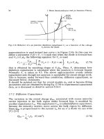
from this the solubility parameter may easily be assessed
(Figure
5.8).
From this equation a useful curve relating
AE
and
Tb
has been compiled and
I20
140
POINT
IN
'C
-
5
10
Figure
5.8.
Relationship between
AE
and boiling point
for
use
in calculating solubility parameters.
(After
Burrel13)
*
The Hildebrand equation and
Figure
5.8,
which
is
derived from it, yield values of
LLY~~
in terms
of units
of
cal/g.
The
SI
units
of
J/g are obtained by multiplying by
a
factor
of
4.1855.
Polymer Solubility
91
From structural formulae
The solubility parameter of high polymers cannot be obtained from latent heat of
vaporisation data since such polymers cannot be vaporised without decomposi-
tion (there may be some exceptions to this generalisation for lower molecular
weight materials and at very low pressures). It is therefore convenient to define
the solubility parameter of a polymer ‘as the same as that of a solvent in which
the polymer will mix in all proportions without heat effect, volume change or
without any reaction or specific association’. It is possible to estimate the value
of
6
for a given polymer by immersing samples in a range of solvents of known
6
and noting the
6
value of best solvents.
In
the case of cross-linked polymers the
6
value can be obtained by finding the solvent which causes the greatest
equilibrium swelling. Such a method is time-consuming
so
that the additive
method of Small’ becomes of considerable value. By considering
a
number of
simple molecules Small was able to compile a list of molar attraction constants
G
for the various parts of a molecule. By adding the molar attraction constants
it was found possible to calculate
6
by the relationship
DZG
a=-
M
where D
is the density
M
is the molecular weight.
When applied to polymers it was found that good agreement was obtained with
results obtained by immersion techniques except where hydrogen bonding was
significant. The method is thus not suitable for alcohols, amines, carboxylic acids
or other strongly hydrogen bonded compounds except where these form only a
small part of the molecule. Where hydrogen bonding is insignificant, accuracy to
the first decimal place is claimed. The
6
values given in
Table
5.7
were computed
by the author according to Small’s method. The values in
Tables
5.4
and
5.5
were
obtained either by computation or from a diversity of sources.
Some molar attraction constants compiled by Small are given in
Table
5.8.
As
an example of the use of Small’s table the solubility parameter of
poly(methy1 methacrylate) may be computed as follows:
The formula for the polymer is shown in
Figure
5.9.
-CH, -C-
I
COOCH,
Figure
5.9
Small’s formula is
6
=
DCG/M
and the value of
ZG/M
will be the same for the
repeating unit as for the polymer.*
*
Small’s method and constants yield values
of
6
in
units
of
(cal/cm,)”*.
The
SI
value
may
be
obtained
by
multiplying by
2.04.
92
Relation
of
Structure
to
Chemical Properties
Table
5.8
Molar attraction constants’ at 25°C
Group
-CH,
-CH,-(single bonded)
-CH<
CH,
=
-CH
=
(double bonded)
>C
=
CHsC-
-c-c-
Phenyl
Phenylene
(o,rn,p)
Naphthyl
Ring (5-membered)
Ring (6-membered)
Conjugation
H
0
(ethers)
CO (ketones)
COO
(esters)
CN
CI single
C1 twinned as in >CC1,
C1 triple as in CCl3
Br
single
I
single:
CF’
in fluorocarbons only
S
sulphides
SH
thiols
ONOZ nitrates
NOz (aliphatic)
PO4
(organic)
?Si (in silicones)
CF,
I
t Estimated
by
H.
Burrell.
Now
M
(for repeating
unit)
=
100
D
=
1.18
2
CH3
at
214
428
1
CH2
at 133 133
1
COO
at 310 310
\/
I
C
at -93-93
__
CG
=
778
/\
Molar attraction
constant
G
214
133
28
-93
190
111
19
285
222
735
658
1146
105-115
95-105
20-30
80-100
70
275
310
410
270
260
250
340
425
150
274
225
315
-440
-440
-500
-
38
DCG
1.18
X
778
8=
-
=
9.2 (cal/cm3)’”
=
18.7
MPa’I2
M
100
Polymer
Solubility
93
In the case of crystalline polymers better results are obtained using an
‘amorphous density’ which can be extrapolated from data above the melting
point, or from other sources.
In
the case of polyethylene the apparent amorphous
density is in the range 0.84-0.86 at
25°C.
This gives a calculated value of about
8.1 for the solubility parameter which
is
still slightly higher than observed values
obtained by swelling experiments.
5.3.4
Thermodynamics and Solubility
The first law of thermodynamics expresses the general principle of energy
conservation. It may be stated as follows: ‘In an energetically isolated system the
total energy remains constant during any change which may occur in it.’ Energy
is the capacity to do work and units of energy are the product of an intensity
factor and a capacity factor. Thus the unit of mechanical energy Cjoule) is the
product of the unit of force (newton) and the unit of distance (metre). Force is the
intensity factor and distance the capacity factor. Similarly the unit of electrical
energy (joule) is the product of an intensity factor (the potential measured in
volts) and a capacity factor (the quantity of electricity measured in coulombs).
Heat energy may, in the same way, be considered as the product of temperature
(the intensity factor) and the quantity of heat, which is
known
as the entropy (the
capacity factor).
It follows directly from the first law of thermodynamics that if a quantity of
heat
Q
is absorbed by a body then part of that heat will do work
W
and part will
be accounted for by a rise in the internal energy
AE
of that body, i.e.
Q
=
AE+W
W=
Q-AE
This expression states that there will be energy free to do work when
Q
exceeds
AE.
Expressed in another way work can be done, that is an action can
proceed, if
AE-Q
is negative. If the difference between
AE
and
Q
is given the
symbol
AA,
then it can be said that a reaction will proceed if the value of
AA
is
negative. Since the heat term is the product of temperature
T
and change of
entropy
AS,
for reactions at constant temperature then
(5.1)
AA
is sometimes referred to as the change in work function. This equation simply
states that energy will be available to do work only when the heat absorbed
exceeds the increase in internal energy. For processes at constant temperature and
pressure there will be a rise in the ‘heat content’ (enthalpy) due both to a rise in
the internal energy and to work done
on
expansion. This can be expressed as
AA
=
AE
-
TAS
AH=AE+PAH
(5.2)
when
AH
is
known as the change in enthalpy and
AV
the change in volume
of
the system under
a
constant pressure
P.
Combining equations
(5.1)
and
(5.2)
gives
AA
+
PAV
=
AH
-
TAS
or
AF
=
AH-TAS
(5.3)
94
This is the so-called free energy equation where
AF
(equal to
AA
+
PAV)
is
known as the free energy.
It has already been shown that a measure of the total work available is given
by the magnitude of
-AA.
Since some of the work may be absorbed in expansion
(PAV)
the magnitude of
-AF
gives an estimate of the net work or free energy
available.
Put in another way, since in equation
(5.3)
we have in effect only added
PAV
to each side of equation (5.1) it follows that energy will only be available to do
work when the heat absorbed
(TAS)
exceeds the change in enthalpy, i.e. when
AF
has a negative value.
The free energy equation is very useful and has already been mentioned in the
previous chapter in connection with melting points. If applied to the mixing of
molecules the equation indicates that mixing will occur if
TAS
is greater than
AH.
Therefore
Relation
of
Structure to Chemical Properties
(1)
The higher the temperature the greater the likelihood of mixing
(an
observed
(2)
The greater the increase in entropy the greater the likelihood of mixing.
(3)
The less the heat of mixing the greater the likelihood of mixing.
fact).
Now it may be shown that entropy is a measure of disorder or the degree of
freedom of a molecule. When mixing takes place it is to be expected that
separation of polymer molecules by solvent will facilitate the movement of the
polymer molecules and thus increase their degree of freedom and their degree of
disorder. This means that such a mixing process is bound to cause an increase in
entropy.
A
consequence of this is that as
AS
will always be positive during
mixing, the term
TAS
will be positive and therefore solution will occur if
AH,
the
heat of mixing is zero or at least less than
TAS.
It
has been shown by Hildebrand and Scott4 that, in the absence of specific
interaction
2
AH
=
v,
[
(%)’”
-
(
$)’”]
ala2
where
V,
is the total volume of the mixture
AX
is the energy of vaporisation
V
the molar volume of each compound
a
the volume fraction of each compound.
Since we have defined the expression
(hx/V)’12
as the solubility parameter
6,
the above equation may be written
AH
=
V,@,
-
S,)a,az
If
6,
and
6,
are identical then
AH
will be zero and
so
AF
is bound to be negative
and the compounds will mix. Thus the intuitive arguments put forward in Section
5.3
concerning the solubility of amorphous polymers can be seen to be consistent
with thermodynamical treatment. The above discussion is, at best, an over-
simplification of thermodynamics, particularly as applied to solubility. Further
information may be obtained from a number of authoritative
source^.^-^
Chemical Reactivity
95
5.4
CHEMICAL REACTIVITY
The chemical resistance of a plastics material is as good as its weakest point. If
it is intended that a plastics material is to be used in the presence of a certain
chemical then each ingredient must be unaffected by the chemical.
In
the case of
a polymer molecule, its chemical reactivity will be determined by the nature
of
chemical groups present. However, by its very nature there are aspects of
chemical reactivity which find
no
parallel in the chemistry of small molecules
and these will be considered in due course.
In
commercial plastics materials there are a comparatively limited number of
chemical structures to be found and it is possible to make some general
observations about chemical reactivity in the following tabulated list of
examples:
(1)
Polyolefins such as polyethylene and polypropylene contain only C-C and
C-H bonds and may be considered as high molecular weight paraffins.
Like the simpler paraffins they are somewhat inert and their major
chemical reaction is substitution, e.g. halogenation.
In
addition the branched
polyethylenes and the higher polyolefins contain tertiary carbon atoms which
are reactive sites for oxidation. Because of this it is necessary to add
antioxidants to stabilise the polymers against oxidation Some polyolefins
may be cross-linked by peroxides.
(2)
Polytetrafluoroethylene contains only C-C and C-F bonds. These are
both very stable and the polymer is exceptionally inert.
A
number of other
fluorine-containing polymers are available which may contain in addition
C-H and C-Cl bonds. These are somewhat more reactive and those
containing C-H bonds may be cross-linked by peroxides and certain
diamines and di-isocyanates.
(3)
Many polymers, such as the diene rubbers, contain double bonds. These will
react with many agents such as oxygen, ozone, hydrogen halides and
halogens. Ozone, and in some instances oxygen, will lead to scission of the
main chain at the site of the double bond and this will have a catastrophic
effect
on
the molecular weight. The rupture of one such bond per chain will
halve the number average molecular weight.
(4)
Ester, amide and carbonate groups are susceptible to hydrolysis. When such
groups are found in the main chain, their hydrolysis will also result in a
reduction of molecular weight. Where hydrolysis occurs in a side chain the
effect
on
molecular weight is usually insignificant. The presence of benzene
rings adjacent to these groups may offer some protection against hydrolysis
except where organophilic hydrolysing agents are employed.
(5)
Hydroxyl groups are extremely reactive. These occur attached to the
backbone
of
the cellulose molecule and poly(viny1 alcohol). Chemically
modified forms of these materials are dealt with in the appropriate
chapters.
(6)
Benzene rings in both the skeleton structure and
on
the side groups can be
subjected to substitution reactions. Such reactions do not normally cause
great changes in the fundamental nature of the polymer, for example they
seldom lead to chain scission or cross-linking.
Polymer reactivity differs from the reactivity of simple molecules in two
special respects. The first of these is due to the fact that a number of weak links
96
Relation
of
Structure to Chemical Properties
exist in the chains of many polymer species. These can form the site for chain
scission or
of
some other chemical reaction. The second reason for differences
between polymers and small molecules is due to the fact that reactive groups
occur repeatedly along a chain. These adjacent groups can react with one another
to form ring products such as poly(viny1 acetal) (Chapter
14)
and cyclised
rubbers (Chapter 30). Further one-step reactions which take place in simple
molecules can sometimes be replaced by chain reactions in polymers such as the
‘zipper’ reactions which cause the depolymerisation of polyacetals and
poly(methy1 methacrylate).
5.5
RADIATION
EFFECTS OF THERMAL, PHOTOCHEMICAL
AND
HIGH-ENERGY
Plastics materials are affected to varying extents by exposure to thermal,
photochemical and high-energy radiation. These forms of energy may cause such
effects as cross-linking, chain scission, modifications to chain structure and
modifications to the side group of the polymer, and they may also involve
chemical changes in the other ingredients present.
In
the absence of other active substances, e.g. oxygen, the heat stability is
related to the bond energy of the chemical linkages present. Table
5.2
gives
typical values of bond dissociation energies and from them it is possible to make
some assessment of the potential thermal stability of a polymer. In practice there
is some interaction between various linkages and
so
the assessment can only be
considered as a guide. Table
5.9
shows the value for
Th
(the temperature at which
a polymer loses half its weight in vacuo at 30 minutes preceded
by
5
minutes
preheating at that temperature) and
K350
the rate constant (in %/min) for
degradation at 350°C.
The high stability of
PTFE
is due to the fact that only C-C and C-F bonds
are present, both of which are very stable. It would also appear that the C-F
bonds have a shielding effect
on
the C-C bonds. Poly-p-xylene contains only
the benzene ring structure (very stable thermally) and C-C and C-H bonds
and these are also stable. Polymethylene, which contains only the repeating
methylene groups, and hence only C-C and C-H bonds, is only slightly less
stable. Polypropylene has a somewhat lower value than polymethylene since the
stability of the C-H at a tertiary carbon position is somewhat lower than that at
a secondary carbon atom. The lower stability of PVC is partly explained by the
lower dissociation energy of the C-Cl bond but also because of weak points
which act as a site for chain reactions. The rather high thermal degradation rate
of poly(methy1 methacrylate) can be explained in the same way. Oxygen-oxygen
and silicon-silicon bonds have a low dissociation energy and do not occur in
polymers except possibly at weak points in some chains.
There is much evidence that weak links are present
in
the chains
of
most
polymer species. These weak points may be at a terminal position and arise from
the specific mechanism of chain termination or may be non-terminal and arise
from a momentary aberration in the modus operandi of the polymerisation
reaction. Because of these weak points it is found that polyethylene,
polytetrafluoroethylene and poly(viny1 chloride), to take just three well-known
examples, have a much lower resistance to thermal degradation than low
molecular weight analogues. For similar reasons polyacrylonitrile and natural
rubber may degrade whilst being dissolved
in
suitable solvents.
Effects
of
Thermal, Photochemical and High-energy Radiation
97
Table
5.9
Thermal degradation
of
selected polymers (Ref.
7)
Polymer
PTFE
Poly-p-xylene
Polymethylene
Polypropylene
Poly(methy1 methacrylate)
Poly(viny1 chloride)
509
432
414
387
327
260
0.0000052
0.002
0.004
0.069
5.2
170
Weak links, particularly terminal weak links, can be the site of initiation of a
chain ‘unzipping’ reacti~n.~?~
A
monomer or other simple molecule may be
abstracted from the end of the chain in such a way that the new chain end is also
unstable. The reaction repeats itself and the polymer depolymerises or otherwise
degrades. This phenomenon occurs to a serious extent with polyacetals,
poly(methy1 methacrylate) and, it is believed, with
PVC.
There are four ways in which these unzipping reactions may be moderated:
(1) By preventing the initial formation of weak links. These will involve,
amongst other things, the use of rigorously purified monomer.
(2)
By deactivating the active weak link. For example, commercial polyacetal
(polyformaldehyde) resins have their chain ends capped by a stable
grouping. (This will, however, be of little use where the initiation of chain
degradation is
not
at the terminal group.)
(3)
By copolymerising with a small amount of second monomer which acts as an
obstruction
to
the unzipping reaction, in the event of this being allowed to
start.
On
the industrial scale methyl methacrylate is sometimes copoly-
merised with a small amount of ethyl acrylate, and formaldehyde
copolymerised with ethylene oxide or 1,3-dioxolane for this very reason.
(4) By the use of certain additives which divert or moderate the degradation
reaction.
A
wide range of antioxidants and stabilisers function by this
mechanism (see Chapter 7).
The problems of assessment of long-term heat resistance are discussed further in
Chapter 9.
Most polymers are affected by exposure to light, particularly sunlight. This is
the result of the absorption of radiant light energy by chemical structures. The
lower the wavelength the higher the energy. Fortunately for most purposes, most
of the light waves shorter than 300nm are destroyed or absorbed before they
reach the surface of the earth and for non-astronautical applications these short
waves may be ignored and most damage appears to be done by rays
of
wavelength in the range 300-400nm. At 350nm the light energy has been
computed to be equal to
82
kcal/mole and it will be seen from
Table
5.2
that this
is
greater than the dissociation energy of many bonds. Whether or not damage is
done to a polymer also depends on the absorption frequency of a bond. A
C-C
bond absorbs at
195
nm and at 230-250 nm and aldehyde and ketone carbonyl
bonds at 187 nm and 280-320 nm.
Of
these bonds it would be expected that only
the carbonyl bond would cause much trouble under normal terrestrial conditions.
98
PTFE
and other fluorocarbon polymers would be expected to have good light
stability because the linkages present normally have bond energies exceeding the
light energy. Polyethylene and PVC would also be expected to have good light
stability because the linkages present do not absorb light at the damaging
wavelength present
on
the earth's surface. Unfortunately carbonyl and other
groups which are present in processed polymer may prove to be a site for
photochemical action and these two polymers have only limited light stability.
Antioxidants
in
polyethylene, used to improve heat stability, may in some
instances prove to be a site at which a photochemical reaction can be initiated.
To
some extent the light stability of a polymer may be improved by incorporating
an additive that preferentially absorbs energy, at wavelengths that damage the
polymer linkage. It follows that an ultraviolet light absorber that is effective in
one polymer may not be effective in another polymer. Common ultraviolet
absorbers include certain salicylic esters such as phenyl salicylate, benzotriazole
and benzophenones. Carbon black is found to be particularly effective
in
polyethylene and acetal resins. In the case of polyethylene it will reduce the
efficiency of amine antioxidants.
In analogy with thermal and light radiations, high-energy radiation may also
lead to scission and cross-linking. The relative stabilities of
various
polymer
structures are shown in
Figure
5.10''.
Whilst some materials cross-link others
degrade (i.e. are liable to chain scission).
Table
5.10
lists some polymers that
cross-link and some that degrade. It is of interest to note that whereas most
polymers of monosubstituted ethylene cross-link, most polymers of disubstituted
ethylenes degrade. Exceptions are polypropylene, which degrades, and PVC,
which either degrades
or
cross-links according to the conditions. Also of interest
is the different behaviour of both PTFE and poly(methy1 methacrylate) when
subjected to different types of radiation. Although both polymers have a good
stability to ultraviolet light they are both easily degraded by high-energy
radiation.
Relation
of
Structure
to
Chemical Properties
0
CH,
>
-C-N-
II
>
-Si-0-
I
>
&
CHI-
>
-
CH,O
-
I
CH3
I
H
Figure
5.10
Relative stabilities
of
various
polymers
to
Ballantine'ol
HH
exposure
by
high-energy
sources.
(After
Aging
and
Weathering
99
Polymers that cross-link
Table
5.10
Behaviour
of
polymers subjected to high-energy radiation’
Polymers that degrade
Polyethylene
Poly(acry1ic acid)
Poly(methy1 acrylate)
Polyacrylamide
Natural
rubber
Polychloroprene
Polydimethylsiloxanes
Styrene-acrylonitrile copolymers
Polyisobutylene
Poly-amethylstyrene
Poly(methy1 methacrylate)
Poly(methacry1ic acid)
Poly(viny1idene chloride)
Polychlorotrifluoroethylene
Cellulose
PTFE
Polypropylene
5.6
AGING AND WEATHERING
From the foregoing sections it will be realised that the aging and weathering
behaviour of a plastics material will be dependent
on
many factors. The
following agencies may cause a change in the properties of a polymer:
(1)
Chemical environments, which may include atmospheric oxygen, acidic
fumes and water.
(2)
Heat.
(3)
Ultraviolet light.
(4)
High-energy radiation.
In
a
commercial plastics material there are also normally a number of other
ingredients present and these may also be affected by the above agencies.
Furthermore they may interact with each other and with the polymer
so
that the
effects of the above agencies may be more, or may be less, drastic. Since
different polymers and additives respond in different ways to the influence of
chemicals and radiant energy, weathering behaviour can be very specific.
A serious current problem for the plastics technologist is to be able to predict
the aging and weathering behaviour of a polymer over a prolonged period of
time, often
20
years or more. For this reason it is desirable that some reliable
accelerated weathering test should exist. Unfortunately, accelerated tests have up
until now achieved only very limited success. One reason is that when more than
one deteriorating agency is present, the overall effect may be quite different from
the sum of the individual effects of these agencies. The effects of heat and light,
or oxygen and light, in combination may be quite serious whereas individually
their effect
on
a polymer may have been negligible. It is also difficult to
know
how to accelerate a reaction. Simply to carry out a test at higher temperature may
be quite misleading since the temperature dependencies of various reactions
differ. In an accelerated light aging test it is more desirable to subject the sample
to the same light distribution as ‘average daylight’ but at greater intensity. It
is,
however, difficult to obtain light sources which mimic the energy distribution.
Although some sources have been found that correspond well initially, they often
deteriorate quickly after some hours of use and become unreliable. Exposure to
sources such as daylight, carbon arc lamps and xenon lamps can have quite
different effects on plastics materials.
100
5.7
DIFFUSION AND PERMEABILITY
Relation
of
Structure
to
Chemical Properties
There are many instances where the diffusion of small molecules into, out of and
through a plastics material are of importance in the processing and usage of the
latter. The solution of polymer in a solvent involves the diffusion of solvent into
the polymer so that the polymer mass swells and eventually disintegrates. The
gelation of PVC with a plasticiser such as tritolyl phosphate occurs through
diffusion of plasticiser into the polymer mass. Cellulose acetate film is produced
by casting from solution and diffusion processes are involved in the removal of
solvent. The ease with which gases and vapours permeate through a polymer is
of importance in packaging applications. For example in the packaging of fruit
the packaging film should permit diffusion of carbon dioxide through the film but
restrain, as far as possible, the passage of oxygen. Low air permeability is an
essential requirement of an inner tube and a tubeless tyre and, in a somewhat less
serious vein, a child’s balloon. Lubricants in many plastics compositions are
chosen because of their incompatibility with the base polymers and they are
required to diffuse out of the compound during processing and lubricate the
interface of the compound and the metal surfaces of the processing equipment
(e.g. mould surfaces and mill roll surfaces). From the above examples it can be
seen that a high diffusion and permeability is sometimes desirable but at other
times undesirable.
Diffusion occurs as a result of natural processes that tend to equal out the
concentration of a given species of particle (in the case under discussion, a
molecule) in a given environment. The diffusion coefficient of one material
through another
(0)
is defined by the equation
where
F
is the weight of the diffusing material crossing unit area of the other
material per unit time, and the differential is the concentration gradient in weight
per ml percm at right angles to the unit area considered.
Diffusion through a polymer occurs by the small molecules passing through
voids and other gaps between the polymer molecules. The diffusion rate will
therefore depend to a large extent
on
the size of the small molecules and the size
of the gaps.
An
example of the effect of molecular size is the difference in the
effects of tetrahydrofuran and di-iso-octyl phthalate
on
PVC. Both have similar
solubility parameters but whereas tetrahydrofuran will diffuse sufficiently
rapidly at room temperature to dissolve the polymer in a few hours the diffusion
rate of the phthalate is
so
slow as to be almost insignificant at room temperature.
(In PVC pastes, which are suspensions of polymer particles in plasticisers, the
high interfacial areas allow sufficient diffusion for measurable absorption of
plasticisers, resulting in a rise of the paste viscosity.) The size of the gaps in the
polymer will depend to a large extent
on
the physical state of the polymer, that
is whether it is glassy, rubbery or crystalline.
In
the case of amorphous polymers
above the glass transition temperature, Le. in the rubbery state, molecular
segments have considerable mobility and there is
an
appreciable ‘free volume’ in
the mass of polymer. In addition, because of the segment mobility there is a high
likelihood that a molecular segment will at some stage move out of the way of
a diffusing small molecule and
so
diffusion rates are higher in rubbers than in
other types of polymer.
Relation
of
Structure
to
Chemical
Properties
Below the glass transition temperature the segments have little mobility and
there is also a reduction of ‘free volume’. This means that not only are there less
voids but in addition a diffusing particle will have a much more tortuous path
through the polymer to find its way through. About the glass transition
temperature there are often complicating effects as diffusing particles may
plasticise the polymers and thus reduce the effective glass transition
temperature.
Crystalline structures have a much greater degree of molecular packing and the
individual lamellae can be considered as almost impermeable
so
that diffusion
can occur
only
in amorphous zones or through zones of imperfection. Hence
crystalline polymers will tend to resist diffusion more than either rubbers
or
glassy polymers.
Of particular interest in the usage of polymers is the permeability of
a
gas,
vapour or liquid through a film. Permeation is a three-part process and
involves solution of small molecules in polymer, migration or diffusion
through the polymer according to the concentration gradient, and emergence of
the small particle at the outer surface. Hence permeability is the product of
solubility and diffusion and it is possible to write, where the solubility obeys
Henry’s law,
P
=
DS
where
P
is the permeability,
D
is the diffusion coefficient and
S
is the solubility
coefficient.
Hence polyethylene will be more permeable to liquids of similar solubility
parameter, e.g. hydrocarbons, than to liquids of different solubility parameter but
of similar size. The permeabilities of a number of polymers to
a
number of gases
are given the
Table
5.11.’2~’3
Stannett and Szwarc’* have argued that the permeability is a product of a
factor
F
determined by the nature of the polymer, a factor
G
determined by the
nature of gas and an interaction factor
H
(considered to be of little significance
and assumed to be unity).
Thus the permeability of polymer i to a gas k can be expressed as
Hence the ratio of the permeability of a polymer i to two gases k and 1 can be seen
to be the same as the ratio between the two
G
factors
Gk
-
p,,
GI
similarly between two polymers (i and
j)
F,
-
P,k
FJ
From a knowledge of various values of
P
it is possible to calculate
F
values
for specific polymers and
G
values for specific gases if the
G
value for one of the
gases, usually nitrogen, is taken as unity. These values are generally found to be
accurate within a factor of
2
for gases but unreliable with water vapour. Some
Toxicity
103
Table
5.12
F
and
G
constants for polymers and gases'*
Polymer
Poly(viny1idene chloride) (Saran)
PCTFE
Poly(ethy1ene terephthalate)
Rubber hydrochloride (Pliofilm)
Nylon
6
Nitrile rubber (Hycar OR-15)
Butyl
rubber
Methyl rubber
Cellulose acetate
(+
15%
plasticiser)
Polychloroprene
Low-density polyethylene
Polybutadiene
Natural rubber
Plasticised
ethyl
cellulose
F
0.0094
0.03
0.05
0.08
0.1
2.35
3.12
4.8
5.0
11.8
19.0
64.5
80.8
84
Gas
ti
1
.o
3.8
21.9
24.2
values are given in
Table
5.12
It will be realised that the
F
values correspond
to the first column of
Table 5.11
and the
G
values for oxygen and carbon dioxide
are the averages of the
PO,/PN,
and
PC02/PN2
ratios.
5.8
TOXICITY
No attempt will be made here to relate the toxicity of plastics materials
to
chemical structure. Nevertheless this is a topic about which a few words must be
said in a book of this nature.
A material may be considered toxic if it has an adverse effect on health.
Although it is often not difficult to prove that a material
is
toxic it is almost
impossible to prove that a material is not toxic. Tobacco was smoked for many
centuries before the dangerous effects of cigarette smoking were appreciated.
Whilst some materials may have an immediate effect, others may take many
years. Some toxic materials are purged out of the body and providing they
do
not
go above a certain concentration appear to cause little havoc; others accumulate
and eventually a lethal dose may be present in the body.
Toxic chemicals can enter the body in various ways, in particular by
swallowing, inhalation and skin absorption. Skin absorption may lead to
dermatitis and this can be a most annoying complaint. Whereas some chemicals
may have an almost universal effect on human beings, others may attack only a
few persons. A person who has worked with a given chemical for some years
may suddenly become sensitised to it and from then
on
be unable to withstand the
slightest trace
of
that material in the atmosphere. He may as a result also be
sensitised not only to the specific chemical that caused the initial trouble but to
a host of related products. Unfortunately a number of chemicals used in the
plastics industry have a tendency to be dermatitic, including certain halogenated
aromatic materials, formaldehyde and aliphatic amines.
In
addition many other chemicals used can attack the body, both externally
and internally,
in
many ways. It is necessary that the effects of any material
used should be known and appropriate precautions taken if trouble is to be
104
avoided. Amongst the materials used in the plastics industry for which special
care should be taken are lead salts, phenol, aromatic hydrocarbons, isocyanates
and aromatic amines.
In
many plastics articles these toxic materials are often
used only in trace doses. Provided they are surrounded by polymer or other
inert material and they do not bleed or bloom and are not leached out under
certain conditions of service it is sometimes possible to tolerate them. This can,
however, be done with confidence only after exhaustive testing. The results
of
such testing of a chemical and the incidence of any adverse toxic effects
should be readily available to all potential handlers of that chemical. There is,
unfortunately, in many countries a lack of an appropriate organisation which
can collect and disseminate such information. This is, however, a matter which
must be dealt with e1~ewhere.l~
Most
toxicity problems associated with the finished product arise from the
nature of the additives and seldom from the polymer. Mention should, however,
be made of poly(viny1 carbazole) and the polychloroacrylates which, when
monomer is present, can cause unpleasant effects, whilst in the
1970s
there arose
considerable discussion on possible links between vinyl chloride and a rare form
of cancer known as angiosarcoma of the 1i~er.l~
Relation
of
Structure to Chemical Properties
5.9 FIRE
AND
PLASTICS
Over the years plastics users have demanded progressively improving fire
performance. By this is meant that plastics materials should resist burning and in
addition that levels of smoke and toxic gases emitted should be negligible. That
a measure
of
success has been achieved is the result of two approaches:
(1)
The development of new polymers of intrinsically better performance.
(2)
The development of flame retardants.
Although many improvements have been made
on
empirical bases, develop-
ments more and more depend
on
a fuller understanding of the process of
combustion. This is a complex process but a number of stages are now generally
recognised. They are:
(1)
Primary thermal processes where energy from an external source is applied
to the polymer, causing a gradual rise
in
temperature. The rate of temperature
rise will depend
on
the rate of supply of energy and
on
the thermal and
geometrical characteristics of the material being heated.
(2)
Primary chemical processes. The external heat source may supply free
radicals which accelerate combustion. The heating material might also be
activated by autocatalytic or autoignition mechanisms.
(3)
Decomposition of the polymer becomes rapid once a certain temperature has
been reached and a variety of products such as combustible and non-
combustible gases and liquids, charred solids and smoke may also be
produced. Some of these products may accelerate further decomposition
whilst others may retard it and this may depend not only
on
the nature of the
compound but also
on
the environmental conditions.
(4)
Ignition will occur when both combustible gases and oxygen are available in
sufficient quantity above the ignition temperature. The amount of oxygen
required for ignition varies from one polymer to another. For example, in an
Fire
and
Plastics
105
atmosphere of
15%
oxygen, polyoxymethylenes (polyacetals) will bum
whereas 49% oxygen is required for PVC to continue burning.
(5) Combustion follows ignition and the ease
of
combustion is a function of the
cohesive energy of the bonds present.
(6) Such combustion will be followed by flame propagation and possibly by
non-flaming degradation and physical changes such as shrinkage, melting
and charring.
A
large amount of smoke and toxic gases may be evolved and
it is worth noting that the number of deaths due to such products is probably
greater than the number due to burning.
Over the years a very large number of tests have been developed to try and assess
the burning behaviour of polymers, this in itself being a reflection of the
difficulty
of
assessing the phenomenon. These tests can roughly be divided into
two groups:
(1)
Simple laboratory tests on the basic polymers and their compounds.
(2) Larger scale tests on fabricated structures.
The first group, i.e. simple laboratory tests, is frequently criticised in that,
although results may be reproducible, they do not give a good indication of how
the material will behave in a real fire situation. On the other hand, the second
group is criticised because correlation between various tests proposed by
different regulatory bodies is very poor. In spite of these limitations there are,
however, a few tests which are very widely used and whose results are widely
quoted.
Perhaps the best known of these is the limited oxygen index test (described for
example in
ASTM
D2863-74). In this test the minimum oxygen fraction in an
oxygenhitrogen mixture that will enable a slowly rising sample of the gas
mixture to support combustion of a candle-light sample under specified test
conditions is measured. Some typical figures
are
given in
Table
5.13.
The reasons for the differences between the polymers are various but in
particular two factors may be noted:
(1)
The higher the hydrogen to carbon ratio in the polymer the greater is the
(2)
Some polymers on burning emit blanketing gases that suppress burning.
tendency to burning (other factors being equal).
Whilst the limiting oxygen index
(LOI)
test is quite fundamental, it does not
characterise the burning behaviour of the polymer. One way of doing this is the
ASTM
D635-74 test for flammability of self-supporting plastics. In this test a
horizontal rod-like sample is held at one end in a controlled flame. The rate of
burning, the average burning time before extinction and the average extent of
burning before extinction (if any) is measured.
The most widely used flammability performance standards for plastics
materials are the Underwriters Laboratories UL94 ratings. These rate the ability
of a material to extinguish a flame once ignited. The ratings given depend on
such factors as rate of burning, time to extinguish, ability to resist dripping and
whether or not the drips are burning.
Tests are carried out on a bar of material
5
inches long and 0.5 inches wide and
are made both horizontally and vertically. In the horizontal test the sample is
held, horizontally, at one end, and a flame, held at about 45", is applied to the
106
Relation
of
Structure
to
Chemical
Properties
Table
5.13
Collected data
for
limiting oxygen index for a variety
of
polymers
Polymer.
Poly acetal
Poly(methy1 methacrylate)
Polypropylene
Polyethylene
Poly(buty1ene terephthalate)
Polystyrene
Poly(ethy1ene terephthalate) (unfilled)
Nylon
6
Nylon
66
Nylon
I1
PPO
ABS
Polycarbonate of his-phenol TMC
Polycarbonate
of
his-phenol A
Pol
ysulphone
Poly(ethy1ene terephthalate) (30% G.F.)
Polyimide (Ciba-Geigy P13N)
Polyarylate (Solvay Arylef)
Liq.
Xtal Polymer (Vectra)
TFE-HFP
Copolymer (Teflon FEP)
Polyether sulphone
Polyether ether ketone
Phenol-formaldehyde resin
Poly(viny1 chloride)
Poly(viny1idene fluoride)
Polyamide-imides
(Torlon)
Polyether-imides (Ultem)
PoIy(pheny1ene sulphide)
Friedel-Crafts resins
Poly(viny1idene chloride)
POly(carb0rdne siloxane)
Polytetrafluoroethylene
Limiting
oxygen index
(%)
15
17
17
17
18
18
21
21-34
25-32
29-35
24
26
30
3 1-33
32
34
34-50
34
34-38
35
35
23-43
44
42-50
44-47
44-53
55
60
62
90
21-30
29-35
Kote
%
oxygen
in
air
=
20.9.
Polymers below the line burn with increasing difficulty as the LO1
mcreabes.
Where a spread
of
figures is given, the higher values generally refer to grades
w~th
mineral or
glass-fibre filler and/or fire retardant. Wlth most other materials, where only one figure is given, higher
values may generally be obtained with the
use of
such additives.
other end. To qualify for an
HB
rating the buming rate should be <76 mm/min for
samples of thickness
<3
mm, and
<38
mm/min for samples of thickness
>3
mm.
This
is
the lowest
UL94
flammability rating.
Greater attention is usually paid to the results of a vertical test, in which the
sample is clamped at the top end and a bunsen flame of height
19
mm is applied
to the lower end at a point
9.5
mm above the top of the bunsen burner (Le. half-
way along the flame). The material is classified as
V-2, V-1
or
V-0
in increasing
order of flammability rating by reference to the conditions given in
Table
5.14.
A
much more severe test is that leading to
UL-94-5V
classifications. This
involves
two
stages.
In
the first stage a standard
5
X
0.5
inch bar is mounted
vertically and subjected to a
5
inch flame five times for
5
seconds duration with
an interval of
5
seconds. To pass the specification
no
specimen may bum with
Fire
and
Plastics
107
Table
5.14
Explunution
v-
0
v-
1
v-
2
No test specimens bum longer than 10 seconds after each removal from the flame.
No
specimens exhibit flaming drip that ignites dry surgical cotton placed 12" below the test
specimen.
Nor
does afterglow persist for longer than
30
seconds.
This rating is essentially identical to
V-0
except that specimens must extinguish within a
30
second interval after flame removal and there should be no afterglow persisting after
60
seconds.
Identical
to
V-1
except that the flaming drip from some specimens ignites the dry cotton
placed below
the
specimens.
flaming or glowing combustion for more than 60 seconds after the fifth flame
application. In addition, no burning drips are allowed that ignite cotton placed
between the samples. The total procedure is repeated with five bars.
In the second stage a plaque of the same thickness as the bars is tested in a
horizontal position with the same-sized flame. The total procedure is repeated
with three plaques. If this results in a hole being formed the material is given a
UL94-5VB rating. If no hole is formed the material is given the highest
classification, UL94-5VA.
The UL94 rating is awarded to a specific grade of material and may also vary
with the colour.
It
is also dependent on the thickness of the sample and this
should also be stated. Clearly, if two materials are given,
for
example, a V-0
rating, that which achieves the rating with
a
thinner sample will be the more fire
retardant.
The importance of specifying grade and thickness may be illustrated by taking
the example of two grades of poly(buty1ene terephthalate) compounds marketed
by General Electric. The grade Valox 325 is given an
HB
rating at 1.47 mm
thickness whereas Valox 310SEO
is
given a V-0 rating at 0.71 mm thickness and
a 5VA rating at 3.05 mm thickness.
Some UL94 flammability ratings are given by way of example in
Table
5.15.
A test used to simulate thermal stresses that may be produced by sources of
heat or ignition such as overloaded resistors or glowing elements is the
IEC
695-2-1
Glow
Wire
Test.
In outline the basis of the test is that a sample of
material is held against a heated glowing wire tip for
30
seconds. The sample
passes the test if any flames or glowing of the sample extinguish within 30
seconds of removal of the glow wire. The test may be carried out at a variety of
test temperatures, such as 550, 650, 750, 850 or 960°C. Amongst materials that
pass the test at 960°C at 3.2 mm thickness are normal grades of poly(pheny1ene
sulphides) and polyether-imides and some flame-retardant-modified grades of
ABS, styrenic
PPOs
and poly(buty1ene terephthalates). Certain polycarbonate/
polyether-imides and polycarbonate/ABS grades even pass the test at the same
temperature but with thinner samples.
To
simulate the effect of small flames that may result from faulty conditions
within electronic equipment, the
IEC
695-2-2 Needle Flame Test
may be used.
In this case
a
small test flame is applied to the sample for a specified period and
observations made concerning ability to ignite, extent of burning along the
sample, flame spread onto adjacent material and time of burning.
108
Relation
of
Structure to Chemical Properties
Table
5.15
Some collected
UL94
flammability ratings
Polymer-
UL
94
Rating
Polycarbonate
Nylon
66
Pol yphthalarnide
Polysulphone
Polyethersulphone
Polybutylene terephthalate
Polyethylene terephthalate GF
PPO
Polyacetal
Polyphenylene sulphide
GF
Liquid Xtal Polymer
pol yether-imide
Pol yketones
ABS Standard Grades
ABS/polycarbonate alloy
Lexan 101
Lexan 120*
Maranyl A100
Amodel AS-1 133
Amodel AF-l14S*
Udel P-1720
Victrex 200P
Pocan B130S
Pocan KL1-7835*
Pocan 4630'
Noryl
N-110
Noryl N-190*
Delrin 500
Fortron grades
Vectra
(30%
GF)
Ultem
1000
PEEKK X941
Cycoloy C2800*
~~
V-2 at
1.04mm
V-0 at 1.04mm, 5VA at 3.0Smm
v-2
HB
at
3.2mm
V-0 at
0.8
mm
v-0
v-0
HB at 0.84 mm
V-0 at
1.55
mm
V-0 at 0.38
mm
HB at 1.65mm
V-0 at 1.52mm, 5VA at 3.12mm
HB
V-0 at 0.4mm
V-0 at 0.4
mm
V-0 at 0.41 mm, 5VA at 1.60mm
V-0 at
0.8mm
HB
V-0 at 1.50mm, SVA at 2.50mm
*
Indicates grade with
flame
retardant added
Records show that more fatalities occur through victims being suffocated by
smoke or poisoned by toxic gases emitted during a fire than by being burnt to
death. This is particularly worrying when it is realised that many additives
incorporated into a polymer to retard its flammability are often found to increase
the amount of smoke emitted as the rate of flame propagation decreases. Most
800
700
$
600
L
-
E
a
>-
500
k
E
400
a
2
0
v)
2
-1
;
300
$
200
u
v)
100
0
1
w
z
0
I
L
J
3
rn
5
n
w
I-
Q
z
a
a
0
3
n
W
Y
!-
n
2
A
0
z
W
H
Figure
5.11.
NBS smoke chamber data in flaming conditions test on 3.2mm samples
Bibliography
109
often the smoke emitted contains large amounts of carbon in the form of soot
which readily obscures light. For this reason,
no
programme of study of the fire
performance of a polymer or flame retardant additive should ignore studies
on
smoke emission and smoke density.
In
addition the gases emitted during burning
should be subjected to chemical analysis and toxicological assessment.
One particularly widely used test is the National Bureau of Standards (NBS)
smoke chamber test. This provides a measure of the obscuration of visible light
by smoke
in
units
of
specific optical density. The NBS smoke test can be
run
in
either
of
two modes:
(1)
Flaming, and
(2)
Non-flaming (Le. smouldering condition).
Figure
5.11
gives some comparative data for a selection
of
polymers subjected to
the flaming condition mode.
References
1. HANSEN, c.
M.,
Ind.
Eng. Chem. Prod. Res. Devpt,
8,
2 (1969)
2.
SMALL,
P.
A.
J.,
J.
Appl. Chem.,
3,
71 (1953)
3. BURRELL, H.,
Interchem. Rev.,
14,
3 (1955); BERNARDO, I.
I.,
and
BURRELL,
H.,
Chapter in
Polymer
4.
HILDEBRAND, J., and
SCOTT,
R.,
The Solubility
of
Non-Electrolytes,
Reinhold, New York, 3rd Edn
5.
TOMPA,
H.,
Polymer Solutions,
Butterworths, London (1956).
6. UILLMEYER, F. w.,
Textbook
of
Polymer Science,
John Wiley, New York (1962)
7. ACHHAMMER,
u.
G., TRYON,
M.,
and KLINE, G. M.,
Mod. Plastics,
37(4), 131 (1959)
8. GRASSIE, N.,
Trans.
inst.
Rubber
ind.,
39,
200 (1963)
9. GRASSIE, N.,
Chemistry
of
High Polymer Degradation Processes,
Butterworths, London (1956)
Science
(Ed. JENKINS, A. D.), North-Holland, Amsterdam (1972)
(1949)
10.
BALLANTINE, D.
s.
Mod. Plastics,
32(3), 131 (1954)
11.
JONES,
s.
T.,
Canad. Plastics, April,
32 (1955)
12.
STANNETT,
v.
T.,
and SZWARC, M.,
J.
Polymer Sci.,
16,
89 (1955)
13.
PAINE,
F,
A.,
J.
Roy.
Inst.
Chem.,
86,
263 (1962)
14. LEFAUX, R.,
Practical Toxicology
of
Plastics
(translation edited
by
HOPF,
P.
P.),
Iliffe, London
15.
KAUFMAN,
M.,
Plastics and Rubber Weekly,
No. 529, May 17, 22 (1974)
(1968)
Bibliography
BILLMEYER,
E
w.,
Textbook
of
Polymer Science,
John Wiley, New York (1962)
CRANK, J., and PARK,
I.
s.,
D@usion in Polymers,
Academic
Press,
London and New York (1968)
GARDON,
I.
L., Article entitled ‘Cohesive Energy Density’ in
Encyclopaedia
of
Polymer Science and
GORDON,
M.,
High Polymers-Structure and Physical Properties,
Iliffe, London, 2nd Edn (1963)
HILDEBRAND,
J.,
and
SCOTT,
R.,
The Solubility
of
Non-Electrolytes,
Reinhold, New York, 3rd Edn
(1
949)
HINDERSINN,
R.,
Article entitled
‘Fire Retardency
’
in
Encyclopaedia
of
Polymer Science and
Technology, Supplement
Vol. 2, pp. 270-340, Interscience, New York (1977)
LEFAUX,
R.,
Practical Toxicology
of
Plastics
(translation edited
by
HOPF,
P.
P.), Iliffe, London
(
1968)
PAULING,
L.,
The Nature
of
the Chemical Bond,
Cornel1 University
Press,
Ithaca, New York, 3rd Edn
(
1960)
RJTCHIE,
P.
D. (Ed.),
P lasticisers, Stabilisers, and Fillers,
Iliffe (published
for
The Plastics Institute),
London (1972)
SAUNDERS, K. I.,
Organic Polymer Chemisfry,
Chapman and Hall, London (1973)
TOMPA,
H.,
Polymer Solutions,
Butterworths, London (1956)
TROITZSCH,
I.,
Plastics Flammability Handbook,
Hanser, Miinchen (English translation) (1983)
Technology,
Vol.
3, p. 833, Interscience, New York (1969)
Relation
of
Structure to Electrical and
Optical Properties
6.1
INTRODUCTION
Most plastics materials may be considered as electrical insulators,
i.e.,
they
are
able to withstand a potential difference between different points of a given piece
of material with the passage of only a small electric current and a
low
dissipation
energy. When assessing a potential insulating material, information
on
the
following properties will be required:
(1)
Dielectric constant (specific inductive capacity, relative permittivity) over a
(2)
Power factor over a range of temperature and frequency.
(3)
Dielectric strength (usually measured in V/O.OOl in or kV/cm).
(4)
Volume resistivity (usually measured in Rcm or am).
(5)
Surface resistivity (usually measured in
0).
(6)
Tracking and arc resistance.
wide range of temperature and frequency.
Typical properties for the selection of well-known plastics materials are
Some brief notes on the testing of electrical properties
are
given in the
tabulated in Table
6.1.
appendix at the end of this chapter.
6.2
DIELECTRIC CONSTANT, POWER FACTOR AND STRUCTURE
The materials in Table
6.1
may be divided roughly into two groups:
(1) Polymers with outstandingly high resistivity,
low
dielectric constant and
negligible power factor, all substantially unaffected by temperature,
frequency and humidity over the usual range of service conditions.
(2)
Moderate insulators with lower resistivity and higher dielectric constant and
power factor affected further
by
the conditions of the test. These materials
are often referred to as polar polymers.
110
Dielectric Constant, Power Factor and Structure
11
1
Table
6.1
Typical electrical properties
of
some selected plastics materials at
20°C
Volume
resistivity
(a
m)
Polymer
Dielectric
strength
(kV/cm)
($
in sample)
PTFE
Polyethylene
(LD)
Polystyrene
Polypropylene
PMMA
PVC
PVC (plasticised)"
Nylon 66b
Polycarbonatec
Phenolicd
Urea formaldehyded
-
+
+-
i.? :,
+
-+
+
+
+ -+
+
-t
+
-+
+
-
+
f
>lo*"
1
02"
102"
>IO''
10Ih
1015
10'5
10'8
1017
1013
10'4
180
180
240
320
140
240
280
145
160
100
120
2.1
2.3
2.55
2.1s
3.7
3.2
6.9
4.0
3.17
5.0-9.0
4.0
2.96
5.0
4.5
I
I
I
Power factor
60
HZ
<0.0003
<0.0003
<0.0003
0.0008
0.06
0.013
0.082
0.014
0.0009
0.08
0.04
104
H~
<0.0003
<0.0003
<0.0003
0.0004
0.02
0.016
0.089
0.04
0.01
0.04
0.3
a
PVC
59%,
di-(Z-ethylhexyl) phthalate
30%.
filler
5%.
atdhiliser
68.
b
0.2% water
content.
c
Makrolon.
d
General
purpose
moulding
compositions.
It is not difficult to relate the differences between these two groups to
molecular structure. In order to do this the structure and electrical properties of
atoms, symmetrical molecules, simple polar molecules and polymeric polar
molecules will be considered in turn.
An atom consists essentially
of
a
positively charged nucleus surrounded by
a
cloud of light negatively charged electrons which are in motion around the
nucleus. In the absence of an electric field, the centres of both negative and
positive charges are coincident and there
is
no external effect of these two
charges
(Figure
6.1
(a)). In a molecule we have a number
of
positive nuclei
surrounded by overlapping electron clouds. In a truly covalent molecule the
centres of negative and positive charges again coincide and there is no external
effect.
If an atom or covalent molecule is placed in an electric field there will be a
displacement of the light electron cloud in one direction and a considerably
smaller displacement of the nucleus in the other direction
(Figure
6.1
(b)).
The
effect of the electron cloud displacement is known as
electron polarisation.
In
these circumstances the centres of negative and positive charge are no longer
coincident.
Figure
6.1.
(a) Atom not subject to external electric field. Centre
of
electron cloud and nucleus
coincident. (b) Electron cloud displacement through application
of
external electric field. (c) Charged
condenser plates separated by vacuum. (d) Condenser plates separated by dielectric