Know and Understand Centrifugal Pumps Episode 11 pps
Bạn đang xem bản rút gọn của tài liệu. Xem và tải ngay bản đầy đủ của tài liệu tại đây (616.16 KB, 20 trang )
Know and Understand Centrifugal Pumps
-
SEALGLAND
SECONDARY STATIC
"0"
RING
STATIONARY
RING
Fiaure
13-3
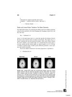
The mechanical seal
The mechanical seal is a device that forms a barrier between rotary and
stationary parts in the pump. The seal must block leakage at three
points (Figure
134):
Between the faces (rotary and stationary) of the
seal.
Between the stationary element and the seal chamber housing
of
the pump.
Between the rotary element and the shaft or sleeve of the pump.
These basic components and functions are common
to
all
seals. The
form, style, and design vary depending on the service and the
manufacturer. The basic theory of its function and purpose
nevertheless, remains the same.
The set screw that transmits the torque from the shaft is connected
to
the rotary face through the spring.
It
also
provides for the positive and
correct positioning of all rotary parts.
SEALING
POINTS
I
BETWEEN SHAFT
AND SEAL
BETWEEN SEAL
AND HOUSING
BETWEEN ROTARY
AND STATIONARY
FACES
-
Fiaure
13-4
184
I
Mechanical Seals
As
the faces wear, the spring extends maintaining the rotary face in
contact with the stationary face. The shaft O-ring should be free
to
move
axially
on the shaft within the operational tolerances of the
bearings. This is called axial play.
The liquid’s pressure in
the
seal chamber holds the faces together and
also provides
a
thin film of lubrication between the faces. This lubricant
is the pumped product. The faces, selected for their low frictional
characteristics, are the only parts of the seal in relative motion. Other
parts would be in relative motion if the equipment is misaligned or with
loose tolerance in
the
bearings.
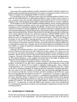
The single, unbalanced, inside mounted mechanical seal
This
type
of seal mounts onto the shaft or sleeve inside the seal chamber
and pump. The pumped liquid comes into contact with all parts of the
seal and approaches the outside diameter of the internally mounted
faces keeping them lubricated. The environment outside
the
pump
approaches the
ID
of the seal faces.
The pressure inside the pump acts upon the faces
to
keep them
together and sealing up
to
about
200
psig. This is
the
most popular
type of mechanical seal in clean (no solid particles or crystals) liquid
service.
A
discharge bypass line connected
to
the seal chamber can
provide additional cooling. Some people prefer a suction bypass
connection with low vapor head (Figure
13-5).
Fiaure
13-5
185
Know and Understand Centrifugal Pumps
The single, outside-mounted, unbalanced
seal
This
type
of seal has the rotary component and face mounted outside
the seal chamber. The springs and drive elements are outside the
pumped liquid. This reduces the problems associated with corrosion
and the accumulation of pumped product clogging the springs. This
seal is popular in the food processing industry. The pumped liquid
arrives
to
the
inside diameter of the faces and seals toward the outside
diameter. The environment outside the pump approaches the
OD
of
the face union. Pressures are limited
to
about 35 psig. Sometimes this
seal can be mounted either inside or outside the pump. This seal is easy
to
install, adjust, and maintain.
It
permits easy access and cleaning of
the pump internal parts, often required in the food processing industry.
The single, balanced, internal mechanical
seal
This balanced seal varies the face loading according
to
the pressure
within the pump. This extends the pressure limits of
the
seal (Figure
The earlier balanced seals incorporate stepped faces mounted onto
a
stepped sleeve or shaft. Later models offer the balance effect without
stepping arrangements. The pumped liquid approaches the
OD
of the
seal’s faces with atmospheric pressure at the
ID of the faces. These seals
are good in the
500
to
600
psig ranges, and they generate less heat than
their unbalanced versions. They’re popular in petroleum refining, and
in general industry where some liquids are prone
to
easy vaporization.
13-6).
Figure
13-6
186
Mechanical
Seals
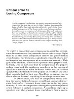
The single, balanced, external mechanical seal
Outside balanced seals permit sealing pressures up
to
about
150
psig.
They offer the other benefits of outside seals, which make them popular
in the food processing industry (Figure
13-7).
In the food production and
OTC
(Over the Counter) Drug industries,
like milk, soups, cough syrup, and juices, outside balanced
seals
are
quite popular. Their design permits easy cleaning of
the
equipment
without pump disassembly. These seals are prominent in the chemical
processing industry because
all
metal components in the seal are located
outside the fluid. This avoids problems of galvanic corrosion.
Advantages
of
0-Rings
1.
2.
3.
The majority of mechanical seal manufacturers make models that
incorporate O-rings as secondary seals. These O-rings offer advantages
over other forms of secondary elastomers.
The O-ring can
flex
and roll
-
There is no need for the shaft
to
slide and rub under the O-ring while under an axial load.
Availability
-
It’s the only elastomeric seal form easily available in
most cities and towns.
Material of construction
-
Almost all elastomeric compounds are
available in the O-ring configuration.
Fiaure
13-7
187
Know and Understand Centrifugal Pumps
4.
New materials
-
As
soon as a new elastomer compound
is
developed,
it
becomes available and produced in the O-ring form.
Examples are ‘Kalraz’, and ‘Zalak’ produced by Dupont,
‘Mas’
produced by 3M, and ‘Parafluor’ by Parker Hannifin.
5.
Reliability
-
Tolerances
to
.003
inch assure reliability.
6.
Vacuum Service
-
The O-ring is the only common popular
elastomeric form that seals in both directions.
7.
High Pressure
-
Installed with back-up rings, O-rings are the
standard in high pressure mechanical sealing.
8.
Controlled Loading
-
The grip onto the shaft is determined by the
seal design and the machined groove, and not the mechanic’s
ability
to
install the seal at the proper dimension and spring
loading.
9.
Easy Installation
-
O-rings slide easily over keyway grooves,
impeller threading and stepped shoulders on sleeves.
10.
Less Shaft Wear
-
Of course O-rings can damage and fret
a
shaft if
the equipment is misaligned, but
it
takes much longer than with
other designs.
11.
Low Cost
-
Why pay more?
12.
Misalignment
-
O-rings can compensate for some misalignment in
the seal chamber face and bore better than any other, elastomer
configuration.
13.
Impossible
to
Install Backward.
vious statements refer
to
designs incorporat
These
pre
machined
yruovn. u-ririyb briuuiu ricver
UT
UULLCU
dydirtbt
d
bpririy ur cridryru
WI~II
d
spring load. They lose many of their desirable properties.
The balance effect
Another concept that has become quite popular in industry is the
balanced mechanical seal. Most manufacturers offer seal models
incorporating the balance feature. This balance is not a dynamic
balance, but instead
a
relationship between the forces tending
to
open
the faces in a mechanical seal and the forces tending
to
close the seal
faces (Figure
1
3-8
) .
188
Mechanical Seals
Fiqure
13-8
BALANCED
SEAL
Advantages
of
balance
1.
Less
heat Generated
-
Less
force between the faces indicates less
heat generated. Heat is the principal reason for premature seal
failure for
two
reasons:
w
It affects the elastomer, which is the seal component most
sensible
to
temperature.
Heat can cause a phase change in the pumped liquid.
-
Some liquids like caustic soda can crystallize with additional
-
Some liquids can solidify with heat (sugars).
-
Some liquids can vaporize with heat (water, propane).
-
Some liquids lose their lubricating qualities when heated
(water).
-
Oils can varnish and carbonize with heat.
-
Some liquids can form a skin with heat (milk, paints).
-
Plated seal faces can suffer heat check with additional heat.
-
Acids become more corrosive when they are heated
heat.
2.
Balanced seals can seal vacuum
-
this
is common in condensate and
3.
High Pressure
-
High pressure was the original purpose bringing
4.
Less
energy consumed
-
Saving energy is more important every day.
5.
Less wear
-
All other conditions being equal, balanced seals wear
less than their unbalanced versions.
6.
High Speed Shafts
-
Shafts at
3,000
rpm or higher causes the seal
faces
to
generate even more heat. Balanced seals reduce the
pressure and force between the faces, thereby generating less heat.
lift
pumps.
about the development of balanced seals.
189
Know and Understand Centrifugal Pumps
7.
Compensates Operational Practices
-
It’s a common practice in
many plants
to
close or throttle a discharge valve with the pump
running
to
meter the flow through the pipes.
8.
Pressure Spikes
-
They’re inherent in the design of many systems.
9.
Eliminate the Re-circulation line
-
A
discharge bypass line is
wasted energy and lost efficiency. Eliminate it with a balanced
seal.
10.
Less
external flush
-
Less
heat generated signifies less cooling
requirements. Balanced seals can be flushed with as little as
1
or
2
gallons per hour.
11.
No need
to
cool hot water
-
If the seal’s elastomer can take the
temperature, and the fluid is pressurized above its vapor pressure,
the cooling line can be eliminated.
Balance explained
by
math
In the following illustration, the pressure inside the pump is
100
psi
and the area of the seal exposed
to
the pressure is
2
in2. Therefore, this
seal is sealing a closing force of
200
pounds (Figure 13-9).
GIVEN: F=PXA
PRESSURE= 1001b/In2
I
.
~
AREA= 21n2
100
psi
FORCE
=
200
LBS
OF FORCE
B
(PSI
x
Area).
Figure 13-9
In the following illustration (Figure 13-10), we
see
that the pressure
drops from
100
psig at the OD of the seal faces
to
0
psig at the ID
Environment
outside
of
the pump
100
lbnnZ
o
ibnn
Figure 13-10
190
Mechanical Sea
Is
of the faces. Therefore the average pressure between the faces
is
50
psig.
r-l
I I
1
In2=
200
Lbs
100
psi
Fiaure 13-11
By
varying the area
of
contact (in this case, projecting 2-in.2 of area
exposed
to
pressure, over 1-in.2 of contact area) between the seal faces
with a constant pressure, the closing force between the faces can be
manipulated (Figure
13-1 1
).
Fiaure 13-12
The illustration above (Figure
13-12)
shows the same concept, but in
the opposite direction. In this case
1
in.2 of area exposed
to
pressure is
projected over
2
in.2
of
contact area. The closing force is
50
lbs.
example utilizing the same concept is a woman's poir
,e*,-
imnr;nt
mevlrr
nn
e
%,;n\,l
Gin
flnnr
frnm
;m rz.cc;
A
common
She can
leave
t~~~ptt~tt
iiiaiha
UI
points. Another example would
sinking by varying the area
of
co
ited high heel shoes.
I
a
vqltyl
Lllc
lluul
Iltl,,sLa210n
of
her shoe heel
be the Eskimo, who can walk on soft snow without
ntact
of
his
footprint with broad snowshoes.
The pressure drop across the faces is not always linear. It may be convex
or concave (Figure
13-13).
High
The pressure drop
is
not
always linear.
It
may
mr-Jp
/
/
be concave or convex.
Pressure
drop
across faces
to
atmosphere
Fiqure 13-13
191
Know and Understand Centrifugal Pumps
50%
50%
of
face contact
50%
force.
area sees closing
Figure 13-14
The illustration above (Figure
13-14)
shows a perfect balance between
opening and closing forces. This is not always convenient.
A
quick drop
in atmospheric pressure, or loss
of
discharge resistance could cause the
faces
to
open.
The following illustration (Figure
13-1
5)
shows a more realistic
balance ratio.
70%
of the face
sees
closing forced and
30%
of the face
(falling below the stepped sleeve on the shaft) does not
see
closing
force.
70%
The majority of balanced seals are
30%
closing force.
designed with
70%
of
the faces seeing
1.4
In2
.61n2
{I
Sleeve
I
Figure 13-15
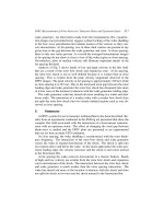
Here is a typical balanced rotary element of a mechanical seal with a
70/30-balance ratio (Figure
13-16).
]
70%
3
30%
Fiaure 13-16
Figure
13-17
shows a balanced, single, rotary element seal mounted
onto the pump shaft, pressed against the stationary face and gland,
mounted in the seal chamber. Note the individual component parts of
the rotary element.
Ca
rt
r
i
dg
e
M
ec
h
a
n
ica
I
Sea
Is
Cartridge mechanical seals are designed
so
that
the
rotary and
stationary elements, the springs and secondary seals, the gland, sleeve
and all accompanying parts are in one integral unit.
It
installs in one
piece instead
of
the numerous individual pieces.
192
Mechanical Seals
1.
Seal posterior (reference point for
5.
Springs.
installation).
6.
Rotary face.
2.
Setscrew.
7.
Stationary face.
3.
Secondary dynamic seal
((0’
ring).
8.
Anti rotation Pin.
4.
Secondary static seal
(10’
ring).
9.
Secondary seals.
Figure
13-17
Advantages of the Cartridge Seal
Pre-assembled at the factory.
Reduced installation time.
Can be installed on most pumps without total pump disassembly.
Requires less technical expertise.
The mechanics don’t have
to
take complicated and confusing
installation dimensions with respect
to
spring tension and face
loading.
The mechanics can’t touch or contaminate the faces of the seal
during installation.
The installation costs less.
The cost of the seal is
less as
a
total unit than the sum of the
individual parts.
Some cartridge seal models have accompanying re-build kits.
Most cartridge designs incorporate ports and hardware for
connecting environmental controls such as:
-
Flush
-
Quench and Drain
Know and Understand Centrifugal Pumps
-
Disaster Bushings for API compliance
Cartridge Seal designs comply with most pump standards like:
-
ANSI
-
API
-
IS0
-
DIN
Here is an illustration
of
a
typical cartridge mechanical seal mounted on
a
shaft in the seal chamber
of
the pump (Figure
13-18).
1.
2.
3.
4.
5.
6.
7.
8.
Static
‘0’
ring.
Spring.
Dynamic
‘0’
ring.
Rotating face.
Stationary face.
Static
‘0’
ring.
Self alioning springs.
Disaster bushing APi.
9.
Setscren.
10.
Gland.
11. Nuts.
12. Spacer for spring tension.
13. Flush line.
14. Cooling and draining.
15.
Pump body.
Figure
13-18
Double
seals
Double seals are also known as dual seals. They are used:
1.
As
an environmental control in difficult sealing applications.
2.
To
compensate for certain operational conditions like:
Inadequate NPSHa.
Operating
a
pump against
a
shut valve or ‘dead heading’
conditions.
194
Mechanical Seals
w
Air aspiration.
w
Entrained gas bubbles.
w
Turbulence.
w
Dry-running the pump.
w
Pumps in intermittent service.
w
When operating just one pump in
a
parallel pump system.
3.
On costly liquids.
4.
With explosive liquids.
5.
With toxic liquids.
6.
With volatile liquids (tendency
to
gas or vaporize).
7.
As the already installed spare seal.
Many plants use dual cartridge seals because:
1.
They can be tested before accepting the seal into stock from the
vendor.
2.
They can be vacuum- and pressure-tested before installation.
3.
In easy applications, these seals reduce maintenance costs by
offering the life of
two
seals with only one installation.
The tandem dual seal
This dual seal has both the rotary units facing in the same direction.
This
type
of seal is recommended for very high pressures. The support
system, and thus the area between the
two
seals, would be pressurized
at
‘/2
the actual seal chamber pressure inside the pump (Figure
13-19,
next page).
For example, if the application is actually
800
psi, you would pressurize
the barrier tank support system and the area between the
two
seals
at
400
psi. This way the inboard seal would seal
400
psi
(800
-
400
=
400
psi) and the outboard seal would
also
seal
400
psi
(400
-
0
=
400
psi).
Each seal independently could seal maybe
500
psi, but not
800
psi.
Together, the
two
seals in
this
tandem arrangement can
seal
800
psi and
higher depending on the barrier tank pressure.
Some purists hold back from calling this type seal a true ‘double or dual
seal’. This is because if one seal in
this
tandem arrangement fails, the
other will immediately fail
too.
195
Know and Understand Centrifugal Pumps
f=i
7
INBOARD SEAL OUTBOARD SEAL
Ficlure
13-19
neral tendency with double seals
is
to think
,-ant
rnstlrl
f-il
-nA
tha
nthar
wm~lrl
L;rL-;n
c
that one seal in a dual
nv
h-oL
r~n
Thir
;c
sr,ht,
The ge
arrangc,llc,lL
cuulu
nasi
aivu
lllc
VIllcl
IvuuIu
cars have a spa
bodies have twc
fail and the other wow
assume
rne
runctio
seals but not th
fails the other
\n
re tire, why a passenger jet
h
kidneys and two eyes. One co
IJ
IL_
z
I!_
lis one in the applications whc
/ill
follow.
c~-tt#
a>
a
>roic
VI
UCILI\
ur.
ir143
L>
vriry
as a pilot and a co-pilot and
why
our
uld become incapacitated, damaged or
ns.
This is the case with other double
!re
it
is most specified.
As
soon
as
one
The tandem dual
seal
is mostly mated
to
a pressurized barrier tank, or a
pumping unit as
the
support system. Support systems are discussed later
in this chapter.
The back-to-back double seal
This
type
of double seal (with back
to
back faces)
is
pressurized above
the
pressure inside the
seal
chamber (Figure
13-20).
It
is recommen-
ded for toxic, explosive, costly, dangerous, and volatile liquids. It is
important
to
maintain the
seal
pressure above the pumped pressure
inside the
seal
chamber.
To
obtain
the
benefits of this seal, it is necessary
to
install a gauge
indicating the actual seal chamber pressure. Sensors and transmitters
can be used
to
monitor and act on a pressure change.
One
of the two
seals can fail without product loss or fugitive emissions. This seal would
be
connected
to
a pumping unit
seen
later in this chapter.
196
Mechanical Seals
Figure 13-20
The face-to-face
dual
seal
This face-to-face double seal is quite versatile (Figure
13-21).
It is
recommended in a wide range of applications depending on the piping
arrangement of its support system.
With its support system pressurized above the seal chamber pressure,
this double seal functions well with toxic and dangerous liquids (like
the back-to-back dual seal). If the support system is pressurized at
'/2
the seal chamber pressure, this
seal
can handle higher pressures where a
single
seal
would fail. If
the
support system should be non pressurized
7
Figure 13-21
197
Know
and Understand Centrifugal Pumps
with forced flow (not induced flow),
it
becomes a good seal for
resolving some operational and design problems in the pumping system
like air aspiration, inadequate NPSHa, and operation away from the
pump’s
BEP.
Let’s
look
at support systems.
Support systems for dual seals
Double seals require some type of support system. The reason is simple.
With
two
seals mounted onto the same shaft, one seal is the principal or
primary seal and the other becomes the secondary or back up seal
already installed. If the primary seal is performing its function and
sealing the pumped liquid, the secondary seal would be running dry,
overheat, burn and self-destruct. Then when the crucial moment
comes, we won’t have a second seal
to
assume the functions, which was
the original reason
to
consider a dual seal.
So
the support system serves
to
lubricate and cool the faces of the
secondary seal while the first is performing its functions. The pressure
applied
to
the support system governs the optimum life of the dual
arrangement, and
it
also governs what happens when one of the
two
seals fails.
There are three distinct support systems for double seals. They are
often referred
to
as ‘barrier tanks’. The term barrier tank was initially
applied
to
the thermal convection tank, although the term today refers
to
any of the three support systems. Each support system has different
attributes.
The thermal convection tank
The Thermal Convection Tank (Figure
13-22).
Can
be
pressurized or un-pressurized.
Conducts a re-circulated flow by thermal convection. When enough
heat is generated inside the mechanical
seal,
it
expands initiating
a
flow into the tank where
it
cools and contracts and is brought again
into the seal.
The tank is sealed and welded, and meets the boiler code for
pressure vessels.
Has a specific location in relation
to
the seal
to
optimize the
convective flow.
Mechanical Seals
Fiaure
13-22
4
Feet-
1.2
Mts
2
t
1
Feet
30
cm
The
turbo
tank
1.
Is
a low pressure system.
2.
Generates its own forced flow with a submersible centrifugal pump.
3.
Is
ideal
for
surviving operational problems like:
Cavitation
w
Inadequate NPSHa
Dry-Running
the
pump
Dead-heading the pump
rn
Vacuum
Operation away from the
BEP
on the curve
199
Know and Understand Centrifugal Pumps
SUPPLY TUBING
SEAL GLAND
Fiaure
13-23
The
turbo
tank
Intermittent service
w
Air aspiration
Turbulence
w
Parallel pumping.
4.
Is
good as an environmental control
(to
reduce heat, dissolve
crystals, absorb gases).
5.
Is
ideal as
the
installed spare.
6.
Continues cooling independent
of
the
process pump.
7.
Is
not location specific in relation
to
the
seal.
8.
Is
not
a
sealed pressure vessel.
The
pumping unit
Works
with water or oil
as
a barrier fluid.
Is
not
a
sealed pressure vessel.
Generates its own re-circulation flow and pressure
with
a
PD
pump.
:al
Seals
I
4
Figure
13-24
The pumping unit
w
Incorporates
flow
and pressure regulators, an in-line filter, and an
internal heat exchanger.
201
Failure Analysis
of
Mecha
n
ica
I
Seals
Causes of premature seal failure
There are numerous reasons why seals fail prematurely. The origin of
the failure can reside in the pumping system, in the pump operation, or
the maintenance shop, the storeroom, or even before the seal arrived
into
the
plant. The first sign of failure normally is liquid on
the
floor.
It’s possible that a failure occurred
to
the seal at the manufacturer.
Nowadays, the companies that we call ‘Manufacturers’ or ‘Factories’ are
actually ‘Parts Assemblers’. It’s likely that no mechanical seal
manufacturer
is
really fabricating their springs, seal faces, or set screws.
These ‘Assemblers’ contract other companies
to
fabricate the pieces.
The failure could have originated in the moment that a sub-contractor
made a piece. The failure could have originated on the seal assembly
line. The majority of the ‘Seal Assemblers’ would perform a static
pressure and vacuum test on their final product. It’s unlikely that they
would perform a dynamic pressure and vacuum test on their creations.
So
if an anti-rotation pin were left out at the factory, it’s likely this
would not be identified until the seal and pump are started. And
although these ‘Assemblers’ don’t want
to
admit it, there are actually
deficient seal designs being delivered
to
the customers that simply don’t
work.
The storeroom techs must protect the mechanical seals handling them
with extreme care. The engineer
or
technician must specify and select
the seal components correctly. The mechanical maintenance technician
must protect the seal at
the
moment of installation. Once the seal is
installed into the pump, the seal requires
the
correct environmental
controls
to
assure optimum life. At this point the work of the
maintenance technician ends.
We
could say that if the mechanical seal fails immediately, or within
moments of the pump start-up, one should investigate
the
events
srl
202
Failure Analysis
of
Mechanical Seals
before the start-up. This failure is probably in the installation, or
handling or manufacture of the seal. If the seal fails in a few days, the
failure might be an incorrect specification of
a
component like an O-ring
seal. But if the mechanical seal fails after three weeks, or
2
or
7
months
of service, now we must consider the operation and/or design of the
system.
On starting the pump and motor, the operators control the service of
the mechanical seal. The operators and the process engineers have a
tremendous influence on the optimal life of the mechanical
seal,
just as
the operator of a car has the most influence over the optimal life of his
automobile. The pump must be operated at, or close
to
it’s best
efficiency point (BEP) on the pump curve.
If the pump is operated away
(to
the left or right) from it’s BEP on the
curve, the pump will vibrate. This damages the bearings and the seal
faces leading
to
premature failure.
Also,
operation
to
the left of the BEP
on the pump curve adds more heat
to
the fluid, which can damage the
O-rings within the seal. In severe cases the fluid can vaporize leaving the
seal to run dry without cooling or lubrication. This damages the seal.
And if the pump is operating
to
the right of the BEP on its curve,
besides
the
vibrations, the poor pump can
go
into cavitation, and this
certainly will kill the seal. If a person insists on mistreating his car,
driving his car like bumper cars at the circus or fair,
it
is not the fault of
the auto mechanic if he can’t maintain the car in
good
operating
condition.
blamed when a mechanical seal
start-up, maybe
you
could point
4
months of operation. This
WOL
operations), or a
amazing is that
t
before.)
u
U)
Llldl
LIIC
IIICCIldlllC>,
ur
the manufacturer, are
fails after
3
months of service.
If
the seal fails
on
to
the mechanic or the seal, but not after
3
weeks or
ild most likely be an operational failure (a failure
in
jesign). And what
is
really
er
been recognized or said
design failure (a failure in the system’s
(
his statement and these words have nevi
There’s a need
to
introduce some logic
to
mechanical seal failure, and
all pump failures. When an operator
sees
a pump leaking and dripping
through the seal, he blames the mechanic, and the mechanic blames
the seal manufacturer. The seal manufacturer blames the pump
manufacturer. The pump manufacturer blames the plant’s purchasing
agent. The purchasing agent blames the engineer, and the engineer
blames the operator. Now we’ve gone all around the block just
to
get
next door. I suppose we could say that when an orchestra gives
a
bad
concert, then no one is
to
blame and everyone is
to
blame.
203