Cardiovascular Imaging A handbook for clinical practice - Part 4 docx
Bạn đang xem bản rút gọn của tài liệu. Xem và tải ngay bản đầy đủ của tài liệu tại đây (573.62 KB, 31 trang )
Transesophageal echocardiography (TEE) overcomes many of these limita-
tions and has been shown in many studies to be far superior to TTE for the iden-
tification of vegetations (Table 7.1). The higher resolution of TEE, multiplane
capabilities, and proximity to the valves explain the better sensitivity of TEE in
detecting vegetations compared with TTE in both native valve IE (90–100%)
and prosthetic valve IE (86–94%).
1,3,8
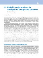
TEE allows a complete assessment of veg-
etation characteristics, such as location, size, and number of vegetations (Fig.
7.4). TEE is also superior to TTE in the detection of pacemaker lead vegetations.
1
A negative TEE examination has a very high negative predictive value for IE
in patients with native heart valve (over 90%).
3
The rare false-negative results
may be related to an incomplete TEE examination, TEE performed very early in
Echocardiography in infective endocarditis 79
Table 7.1 Comparative value of transthoracic echocardiography (TTE) and
transesophageal echocardiography (TEE) in the diagnosis of valvular vegetations.
Transthoracic echo Transesophageal echo
Prostheses Sensitivity Specificity Sensitivity Specificity
Reference n (%) (%) (%) (%) (%)
Mügge et al. (1989)
4
91 24 58 – 90
Shively et al. (1991)
5
66 18 44 94 98 100
Daniel et al. (1993)
6
33 100 36 – 82
Shapiro et al. (1994)
7
68 – 68 91 87 91
Figure 7.4 Transesophageal
echocardiography demonstrating large
mitral vegetation. LA, left atrium; LV,
left ventricle.
BCI7 6/18/05 11:17 AM Page 79
the infectious process before the development of vegetations, or vegetations
that are too small to be detected or have already embolized. Careful multiplane
TEE examination might reduce the likelihood of false-negative results.
In patients with prosthetic valves, false-negative results are more prone to
occur, possibly because of incomplete visualization, presence of artifacts, and
interference. In these patients, a negative TEE does not completely exclude the
diagnosis of IE.
Although TEE specificity for IE vegetations is high (88–100%), possible false-
positive findings may occur in certain situations. Underlying native valvular ab-
normalities such as myxomatous mitral valve disease, non-specific valvular
thickening, Lambl’s excrescences, or fibroelastomas may mimic vegetations.
Echocardiography does not permit differentiation between active versus healed
vegetations or between bacterial versus non-bacterial thrombotic vegetations,
such as those observed in systemic lupus erythematosus, antiphospholipid syn-
drome, or marantic endocarditis. In patients with prosthetic valve, common
findings such as sutures or prosthetic strands should not be confused with veg-
etations. Distinction between vegetations and prosthetic thrombus is often
impossible, and other prosthetic abnormalities such as bioprosthetic leaflet
degeneration can be also difficult to differentiate from vegetations.
Detection of abscesses and perivalvular complications
Aortic location, prosthetic valve IE, and staphylococcal infection are the best
predictive factors for IE associated perivalvular complications. TEE is strongly
indicated in these high-risk patients to identify perivalvular complications. The
presence and size of vegetations do not seem helpful in predicting perivalvular
extension of the infection.
9
Abscesses may extend into contiguous tissue, espe-
cially the mitral–aortic intervalvular fibrosa, resulting in the formation of cavi-
ties, pseudoaneurysms, and fistulas. Mitral annular abscesses are less frequent,
and almost always in patients with mitral prostheses.
Echocardiographically, these abscesses appear as a perivalvular region of in-
creased thickness (greater than 10 mm) and reduced echo-density, without ev-
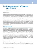
idence of flow with color Doppler (Fig. 7.5). A pseudoaneurysm is defined as a
pulsatile, echo-free, perivalvular cavity with flow communicating with the car-
diovascular lumen. A fistula is defined as a color Doppler tract communicating
two adjacent cardiac chambers (Fig. 7.6).
9
The superiority of TEE over TTE in the diagnostic of periannular complica-
tions is well established.
9,10
Only approximately 25% of paravalvular abscesses
are detected by TTE, whereas sensitivity and specificity are very high with TEE
(87% and 95%, respectively, in the Daniel series
10
). Combined with spectral
and color Doppler techniques, TEE can also identify the abnormal communicat-
ing flow in pseudoaneurysms and fistulae. TEE also provides information about
the localization and extension of paravalvular abscesses. Intervalvular fibrosa
abscesses and pseudoaneurysms are more frequently detected by TEE than by
TTE.
False-positive and false-negative TEE results may occur in some cases.
80 Chapter 7
BCI7 6/18/05 11:17 AM Page 80
Echocardiography in infective endocarditis 81
Figure 7.5 Transesophageal echocardiography demonstrating a region of reduced echo
density with no flow in the periannular aortic ring (arrows). Abscess was confirmed on
surgery. LA, left atrium; LV, left ventricle; LVOT, left ventricular outflow tract.
Figure 7.6 Transesophageal echocardiography demonstrating perforation of an
aneurysm of the anterior mitral leaflet (left) secondary to infection of the mitral–aortic
intervalvular fibrosa in an aortic endocarditis. Color flow Doppler shows the large
eccentric jet of mitral regurgitation through the perforation (right). LA, left atrium; LV,
left ventricle; RV, right ventricle.
BCI7 6/18/05 11:17 AM Page 81
Abscesses may be missed when they are too small. Diagnostic accuracy of TEE is
better for pseudoaneurysms than for abscesses.
9
Although periannular compli-
cations are frequent in patients with prosthetic valve IE, their identification
—
even with TEE
—
may be challenging. Prostheses, especially mechanical valves,
may create confusing images because of artifacts and shadows of the prosthetic
material and eccentric color Doppler jets. Anterior aortic abscesses may be
missed with TEE in patients with prosthetic valves.
82 Chapter 7
Figure 7.7 Transesophageal echocardiography (TEE) showing a large vegetation
attached to the tip of non-coronary aortic valve with complete prolapse of the cusp.
Case Presentation (Continued)
TEE showed a large vegetation attached to the tip of the non-coronary aortic
valve with complete prolapse of the cusp (Fig. 7.7). Severe aortic regurgitation
was confirmed with color flow Doppler (Fig. 7.8). A large abscess was observed at
the level of the posterior aortic root, with no flow (Fig. 7.9a). This abscess
extended to the subaortic region of mitral–aortic intervalvular fibrosa (Fig.
7.9b). The patient underwent cardiac surgery the same day. At the time of
surgery, there was complete destruction of the non-coronary aortic valve, with
multiple vegetations. The periannular abscess, extending to the intervalvular
fibrosa, was confirmed. The patient underwent aortic valve replacement with a
homograft and exclusion of the abscess.
Cultures of the aortic valves grew coagulase-negative Staphylococcus which
responded to 6 weeks of rifampicin and oxacillin therapy. The patient did well
after 6 weeks of treatment.
BCI7 6/18/05 11:17 AM Page 82
New valvular dysfunction
The assessment of valvular regurgitation is based on a comprehensive utiliza-
tion of both TTE and TEE, coupled with pulsed, color flow, and continuous wave
Doppler. This allows a complete evaluation of underlying valve disease, mecha-
nism, and severity of valvular regurgitation.
In typical situations, diagnosis of acute, severe, valvular regurgitation is
strongly suggested by the mechanisms of valve dysfunction, destruction, or per-
foration, with flail leaflet, associated with typical Doppler findings of severe re-
gurgitation. Valvular perforation, especially in the aortic position is associated
with an adverse outcome. TTE can detect or suggest valvular perforation in IE,
but TEE better defines this complication.
Identification of new paraprosthetic regurgitation is a major echocardio-
graphic finding in patients suspected of having IE. Because of its superiority in
determining the spatial location of regurgitant jets, TEE is the modality of choice
for the diagnosis of paravalvular regurgitation. However, small intraprosthetic
regurgitant jets, present in the majority of normal prostheses, should not be
confused with paraprosthetic leakage.
Prognosis of infective endocarditis
Echocardiography provides important prognostic information in patients with
IE that can help medical or surgical decisions.
Prognosis related to the presence and size of the vegetations
The presence and morphology of echocardiographically documented vegeta-
tions are associated with a higher rate of complications in IE. Several studies
Echocardiography in infective endocarditis 83
Figure 7.8 Confirmation of severe aortic regurgitation with color flow Doppler.
BCI7 6/18/05 11:17 AM Page 83
84 Chapter 7
(a)
(b)
have shown a significant association between morphologic characteristics of
the vegetations and the incidence of embolic events. Both vegetation size and
mobility are predictive of embolic events. The risk of embolization is particul-
arly high in large and highly mobile mitral valve IE and in staphylococcal infec-
tion. In a recent study of 178 consecutive patients with definite IE as established
by the Duke criteria, patients with vegetations larger than 10 mm had a 60% in-
cidence of emboli, while severely mobile vegetations larger than 15 mm had an
Figure 7.9 Transesophageal echocardiogram (TEE) showing a large abscess at the level
of the posterior aortic root: (a) with no flow; (b) with extension to the subaortic region
of mitral–aortic intervalvular fibrosa.
BCI7 6/18/05 11:17 AM Page 84
83% incidence of emboli.
11
Embolism before initiation of antimicrobial treat-
ment, or increase in vegetation size during treatment, may also predict later em-
bolism.
12
A high incidence of embolic events is also observed in patients with
right heart IE.
11
The indication for early surgery in patients with large vegeta-
tions should be discussed individually for each patient. Although large and
highly mobile vegetations, especially on the mitral valve, are more prone to
embolize, indications for surgery should not be purely based on echocardio-
graphic parameters,
1,13
but should also take into account the causative agent,
the presence of complications such as heart failure, the feasibility of valve
repair, and the extracardiac condition of the patient.
Early detection of complications
Periannular extension of the infection is associated with more complications,
poor clinical outcome, and frequent need for surgery.
9
Early and accurate identification of periannular extension or prosthetic de-
hiscence in patients suspected of having IE are critical for appropriate patient
management and surgical decisions. Surgical repair is more difficult when these
complications are diagnosed at too late a stage.
Evaluation of hemodynamic consequences of valvular regurgitation
Besides the identification and quantification of valvular regurgitation, echocar-
diography allows evaluation of their hemodynamic consequences. Acute, se-
vere aortic or mitral regurgitation with signs of ventricular failure is associated
with an adverse outcome and requires early surgical management.
When acute regurgitation is superimposed on chronic regurgitation, inter-
pretation of echocardiographic data may be more difficult.
A major role of echocardiography in prognostic evaluation is the identifica-
tion of the causes and severity of congestive heart failure. Chamber size,
segmental and global wall motion, ejection fraction, and left ventricular and
pulmonary artery pressures should be defined and monitored during follow-
up. Although no or moderate left ventricular dilatation favors acute regurgita-
tion, left ventricular enlargement and left ventricular dysfunction may be
present in both acute and chronic situations. Assessment of the progression of
the impact of regurgitation on left ventricular volumes and function, along with
clinical evaluation, is needed for adequate timing of intervention.
Guidelines for the use of echocardiography in suspected or
definite infective endocarditis
The diagnostic value of echocardiography in suspected IE differs according to
the pretest probability of the disease.
14
Although TTE is often performed to ex-
clude IE in patients with low probability of IE, it has been shown that echocar-
diography has a low diagnostic yield and low impact on clinical management in
these patients.
14
In addition, false-positive results are more likely to occur in
these situations. Thus, it could be recommended to perform echocardiography
(especially TEE) only in patients with a reasonable probability of the disease. In-
Echocardiography in infective endocarditis 85
BCI7 6/18/05 11:17 AM Page 85
deed, recent ACC/AHA and ESC recommendations have emphasized the need
for a selective approach to TEE in suspected IE (Fig. 7.10):
1,13
• When TTE images are of good quality and prove to be negative and there is
only a low clinical suspicion of IE, endocarditis is unlikely, TEE is not necessary,
and other diagnoses should be considered.
13
In patients with a high or interme-
diate probability of IE, TEE should be performed if TTE is negative or inconclu-
sive, or in patients with prosthetic valves. Negative predictive value is very high
(95%) when both TTE and TEE are negative.
1
• When TTE is positive, use of TEE is recommended if complications are sus-
pected, or in high-risk patients (prosthetic valve, previous endocarditis, con-
genital heart disease, staphylococcal IE), or before surgery.
1,13
• If TTE and TEE results remain negative, but clinical condition still leads to sus-
picion of IE, in the absence of an alternative source of infection, TEE should be
repeated within 1 week.
13
More generally, skilled operators and good-quality images are required to
avoid imaging pitfalls. As often as possible, abnormal findings should be com-
pared with previous examinations, especially in the postoperative period, to
avoid false-positive results. Repeated examinations should be performed in
difficult cases to follow the progression of images. The time interval between
TEE studies should be individualized according to clinical, bacteriologic, and
echocardiographic findings.
86 Chapter 7
Figure 7.10 Algorithm for the use of echocardiography in suspected infective
endocarditis. (Modified from Bayer et al. [1998]
1
and Graupner et al. [2002].
9
)
BCI7 6/18/05 11:17 AM Page 86
Conclusions
Echocardiography has a major role in the diagnosis, risk stratification, and
management of patients with IE. Identification of vegetations, early detection
of complications, identification of valvular dysfunction and their hemodynam-
ic consequences are important information provided by echocardiography that
can help in risk stratification and clinical decision-making.
References
1 Bayer AS, Bolger AF, Taubert KA, et al. Diagnosis and management of infective endo-
carditis and its complications. Circulation 1998;98:2936–48.
2 Durack DT, Lukes AS, Bright DK. New criteria for diagnosis of infective endocarditis:
utilization of specific echocardiographic findings. Duke Endocarditis Service. Am J
Med 1994;96:200–9.
3 Shively BK, Gurule FT, Roldan CA, Leggett JH, Schiller NB. Diagnostic value of trans-
esophageal compared with transthoracic echocardiography in infective endocarditis.
J Am Coll Cardiol 1991;18:391–7.
4 Mugge A, Daniel WG, Frank G, Lichtlen PR. Echocardiography in infective endo-
carditis: reassessment of prognostic implications of vegetation size determined by the
transthoracic and the transesophageal approach. J Am Coll Cardiol 1989;14:631–8.
5 Shively BK, Gurule FT, Roldan CA, Leggett JH, Schiller NB. Diagnostic value of trans-
esophageal compared with transthoracic echocardiography in infective endocarditis.
J Am Coll Cardiol 1991;18:391–7.
6 Daniel WG, Mugge A, Grote J, et al. Comparison of transthoracic and transesophageal
echocardiography for detection of abnormalities of prosthetic and bioprosthetic
valves in the mitral and aortic positions. Am J Cardiol 1993;71:210–5.
7 Shapiro SM, Young E, De Guzman S, et al. Transesophageal echocardiography in di-
agnosis of infective endocarditis. Chest 1994;105:377–82.
8 Daniel WG, Mugge A, Grote J, et al. Comparison of transthoracic and transesophageal
echocardiography for detection of abnormalities of prosthetic and bioprosthetic
valves in the mitral and aortic positions. Am J Cardiol 1993;71:210–5.
9 Graupner C, Vilacosta I, SanRoman J, et al. Periannular extension of infective endo-
carditis. J Am Coll Cardiol 2002;39:1204–11.
10 Daniel WG, Mugge A, Martin RP, et al. Improvement in the diagnosis of abscesses
associated with endocarditis by transesophageal echocardiography. N Engl J Med
1991;324:795–800.
11 Di Salvo G, Thuny F, Rosenberg V, et al. Endocarditis in the elderly: clinical, echocar-
diographic, and prognostic features. Eur Heart J 2003;24:1576–83.
12 Vilacosta I, Graupner C, San Roman JA, et al. Risk of embolization after institution of
antibiotic therapy for infective endocarditis. J Am Coll Cardiol 2002;39:1489–95.
13 Horstkotte D, Follath F, Gutschik E, et al. Guidelines on prevention, diagnosis and
treatment of infective endocarditis executive summary: the task force on infective
endocarditis of the European Society of Cardiology. Eur Heart J 2004;25:267–76.
14 Lindner JR, Case RA, Dent JM, Abbott RD, Scheld WM, Kaul S. Diagnostic value of
echocardiography in suspected endocarditis: an evaluation based on the pretest prob-
ability of disease. Circulation 1996;93:730–6.
Echocardiography in infective endocarditis 87
BCI7 6/18/05 11:17 AM Page 87
BCI7 6/18/05 11:17 AM Page 88
Section two
Coronary artery disease
BCI8 6/18/05 11:19 AM Page 89
BCI8 6/18/05 11:19 AM Page 90
CHAPTER 8
Coronary imaging
and screening
Koen Nieman and Pim J. de Feyter
Introduction
Non-invasive imaging of the coronary arteries was first demonstrated by mag-
netic resonance imaging (MRI) in the early 1990s. Since these first images, the
capabilities of cardiac MRI have rapidly developed, even though cardiac MRI
has proven most useful for functional assessments and infarct imaging. Parallel
to these developments, computed tomography (CT) has evolved into a reliable
cardiac imaging modality. Electron beam CT, followed by multislice spiral CT
have proven able to provide high-resolution imaging of the coronary lumen as
well as the diseased coronary artery wall. The time has come to determine the
role of non-invasive coronary imaging, merely as an alternative to conven-
tional angiography, or a complementary addition to non-invasive functional
imaging.
Magnetic resonance imaging
Of the currently applied non-invasive coronary imaging techniques, MRI is the
most attractive in terms of patient safety, because it does not require potentially
nephrotoxic contrast media or radiation. High-resolution images of the heart
can be obtained in any orientation, and with excellent tissue differentiation.
MRI is a tomographic imaging technique based on the behavior of protons
(hydrogen nuclei) in a magnetic field. After excitation by a radiofrequency (RF)
pulse, protons will emit an RF signal over a short period of time while they re-
turn to their aligned position. The time required for complete relaxation de-
pends on the physical and biochemical environment of the proton, which is
exploited by MRI to create images using various pulsing sequence designs. MRI
is recognized as an important tool in cardiovascular medicine for imaging of car-
diovascular morphology, myocardial perfusion, and myocardial viability. It is
considered the gold standard for ventricular function assessment.
1
Magnetic resonance coronary angiography
Coronary imaging by MRI was first demonstrated in the early 1990s. Using var-
91
BCI8 6/18/05 11:19 AM Page 91
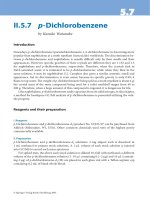
ious 2D and 3D, breath-hold and free-breathing acquisition protocols, obstruc-
tive disease in the coronary arteries and bypass grafts can be visualized (Fig.
8.1). Although initial reports were very promising, comparative studies with
numerous MRI techniques against conventional coronary angiography have
shown that lesions can be detected in the proximal coronary artery segments
with a reasonable sensitivity and specificity, which remained at 38–93% and
42–97%, respectively.
2
Despite steady technologic advancement, MRI has not
yet reached a level of robustness that allows high-quality imaging of the entire
coronary artery tree with sufficient spatial resolution, temporal resolution, and
contrast-to-noise. Additional limitations include the long examination times,
inability to scan and/or evaluate patients with implanted metal objects,
ECG–signal distortion during scanning, suppression of signal from fat tissue,
and motion artifacts resulting from averaging of data that was acquired over
several heart cycles.
1
Magnetic resonance plaque imaging
MRI can express numerous biochemical properties of the tissue being investi-
gated, which make this modality ideal for tissue differentiation. By exposing
atherosclerotic tissue to different pulse sequences that focus on different bio-
chemical parameters, various plaque components can be identified, including
fibrous or lipid tissue, calcium, and thrombus. Most of these experiences have
been acquired in larger vessels, namely the carotid arteries and the aorta. In
these vessels accurate measurements of the plaque size can be performed,
which allows monitoring of plaque progression or regression.
3
High-resolution
coronary plaque imaging is a challenging and time-consuming procedure and
only limited coronary sections can be imaged within a reasonable examination
time.
92 Chapter 8
Figure 8.1 Cardiac magnetic
resonance imaging (MRI). Volume-
rendered MR angiogram showing a
venous bypass graft arising from the
aortic root along the anterior surface of
the heart, with anastomoses to
branches of the left coronary artery,
which are not well seen.
BCI8 6/18/05 11:19 AM Page 92
Electron-beam computed tomography
Electron-beam computed tomography (EBCT) is a fast CT technology, specifi-
cally designed for imaging of the heart. Because of the lack of mechanically
moving parts, the time to acquire one image can be as short as 50 ms. The acqui-
sition of images is prospectively triggered by the ECG. Based on the interpreta-
tion of the recorded ECG trace, the scan is initiated during the predicted diastolic
phase of the next heart cycle.
Non-enhanced imaging of coronary calcium
The presence of calcium in the cardiovascular system is possible with any X-ray
modality, as well as ultrasound and MRI. Without the use of contrast media, CT
is able to detect small atherosclerotic calcifications in the coronary arteries.
Since the early 1990s, EBCT has been used for the detection and quantification
of coronary calcium.
By detecting calcium in the coronary arteries, the evidence for atherosclero-
sis is compelling. An exceptional cause for vessel wall calcification is Möncke-
berg media sclerosis. However, the inability to detect calcium does not exclude
the possibility of non-calcified atherosclerotic plaque being present. It has been
shown extensively that the calcium score is not useful as an reliable indicator of
obstructive coronary artery disease.
4
While calcification of the individual lesion
may indicate plaque stability, it has been proven that the age-adjusted amount
of coronary calcium is correlated to the occurrence of coronary events. It holds
additional predictive value over the traditional risk factors for the long-term risk
of developing symptomatic coronary artery disease. Whether widespread
screening of asymptomatic individuals for coronary calcium is desirable re-
mains a matter of debate. Selective use in those with an intermediate coronary
risk, to determine whether intensive risk factor modification and medical inter-
vention is warranted, has been suggested.
5
The use of non-enhanced EBCT as a
triage tool has been explored, to exclude coronary involvement in patients with
acute chest pain at the emergency department. In a relatively small study no
coronary events occurred in those without coronary calcium in the period after
they visited the hospital.
6
However, because the absence of coronary calcium
does not exclude coronary plaque (rupture), particularly in young patients,
these studies had little influence on clinical practice.
EBCT coronary angiography
Minimally invasive imaging of the coronary lumen by EBCT is possible by
injecting iodinated contrast medium into a peripheral vein. A number of com-
parative studies with conventional angiography have been performed since
1997. In most studies, assessment was limited to the proximal and middle coro-
nary segments. After exclusion of segments or vessels with non-diagnostic
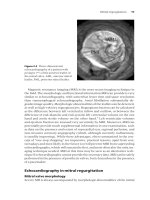
image quality (10–28%), the sensitivity and specificity to detect significant
coronary artery disease was in the range 74–92% and 63–94%, respectively
(Fig. 8.2).
4
Contrast-enhanced EBCT has also been used to detect bypass graft
Coronary imaging and screening 93
BCI8 6/18/05 11:19 AM Page 93
occlusion as well as non-complete graft obstruction with a good sensitivity and
specificity.
The advantage of EBCT is the high temporal resolution and the relatively low
radiation exposure, compared with multislice spiral CT (MSCT). Disadvantages
include the lower spatial resolution in the longitudinal axis (3.0 mm detector
width), the limited longitudinal coverage or long breath-hold period, and the
lower signal-to-noise ratio. Widespread clinical use has further been limited by
the intensive maintenance of the system and inferior suitability for non-cardiac
examinations. Studies with recently innovated EBCT technology, which in-
cludes double 1.5 mm-detector row, multiphasic acquisition protocols, and
50 ms acquisition time, are awaited.
Multislice spiral computed tomography
The most recent non-invasive coronary imaging modality is multislice spiral
computed tomography (MSCT), or multidetector-row helical computed to-
mography (MDCT). Rather than the step-and-shoot approach of sequential
scanners, MSCT requires continuous patient propagation while data are ac-
quired by up to 64 detector rows, allowing fast imaging of large body sections.
By using an overlapping scan protocol each (longitudinal) position is sampled
(by different detectors) during at least one entire heart cycle, and ECG-syn-
chronized images of the entire heart can be created at any temporal position
within the heart cycle (Fig. 8.3). Current scanners have a rotation time as short
as 330 ms, resulting in a temporal resolution of 165ms or less. Although this
may be sufficient to avoid severe motion artifacts in the majority of patients, use
of beta-blocking medication is recommended in those with a heart rate over
65–70 min
-1
, to optimize image quality. To handle the enormous amount of
94 Chapter 8
Figure 8.2 Coronary electron beam
computed tomography (EBCT).
Volume-rendered reconstruction of an
EBCT coronary angiogram. The
proximal left anterior descending
coronary artery is severely stenosed
(arrow). CX, left circumflex branch.
BCI8 6/18/05 11:19 AM Page 94
image data (up to 300 axial slices per reconstructed cardiac phase), and present
findings to referring physicians, advanced image processing tools have been de-
veloped (Figs 8.4–8.7; Video clips 1–7 ).
MSCT coronary angiography
Detection of coronary stenoses with four-slice MSCT could be demonstrated
with a reasonable diagnostic accuracy compared with conventional angiogra-
phy.
7
These studies also exposed the limitations of this technique, in terms of
motion artifacts, long acquisition times, and the complicated evaluation of cal-
cified coronary arteries. The relatively slow rotation of four-slice scanners, and
the inherent poor results in patients with high heart rates, promoted the use of
beta-blockers.
8
Comparative studies using 16-slice MSCT incorporated heart
rate modulation in their protocol. In combination with the improved scanner
performance (i.e. 420 ms rotation time), more and thinner detector rows,
general image quality, as well as diagnostic accuracy could be improved (Figs
Coronary imaging and screening 95
Heart rate modulation
(beta-blocker IV/PO)
Overview & planning
(Test bolus)
Post-processing
Evaluation
(Bolus tracking)
Data acquisition (15s)
ECG-gated
Image reconstruction
Figure 8.3 Multislice spiral computed tomography
(MSCT) data acquisition. Schematic overview of the
data acquisition with MSCT. Either a test bolus prior to
the acquisition, or tracking the arrival of the bolus
followed by the data acquisition can be used to
synchronize data acquisition with contrast
enhancement. Images are reconstructed from the
spiral data (at any time-point within the cardiac cycle),
gated to the recorded ECG.
BCI8 6/18/05 11:19 AM Page 95
96 Chapter 8
Figure 8.4 MSCT coronary angiography. A severely stenosed, partially calcified lesion
can be identified in the left anterior descending coronary artery (LAD) on volume-
rendered CT angiography images (A,B) and by conventional coronary angiography (D).
The right coronary artery (RCA) shows no significant stenotic disease, on the curved
multiplanar reformatted CT angiogram (C). See also Video clips 1–7 .
8.4–8.6). By reducing the average heart rate to less than 60 min
-1
, and limiting
the evaluation to larger coronary vessels (≥2.0 mm diameter), a high sensitivity
and specificity could be achieved without exclusion of less-interpretable scans
(Table 8.1).
9,10
Overestimation of stenosis severity, particularly in calcified ves-
sels, resulted in a substantial number of false-positive diagnoses and a modest
positive predictive value. Investigators who extended the evaluation to smaller
coronary segments, and included all ≥1.5-mm vessels, found a lower diagnostic
accuracy, particularly in these smaller segments.
11,12
Graft imaging
Imaging of (venous) bypass grafts is gratifying because of their large size and rel-
ative immobility. Graft occlusion can be detected with high accuracy, but also
stenosis and obstructive disease in specific sequential graft segments can be vis-
ualized (Fig. 8.7). Assessment of the native coronary artery system is more
BCI8 6/18/05 11:19 AM Page 96
Coronary imaging and screening 97
Figure 8.5 MSCT coronary angiography. A CT coronary angiogram in a patient with
two-vessel disease. A partially calcified, stenotic lesion (long arrow) can be observed in
the left anterior descending coronary artery (LAD), between a small septal and the
second diagonal branch (D2) (A,B,C). A large, mostly non-calcified plaque (short
arrow) can be identified on CT just distal to the stenotic lesion (A,C). This lesion is
poorly visualized on conventional angiography (B). Because of vessel remodeling, the
lesion does not cause narrowing of the vessel lumen (A). A significantly stenosed, non-
calcified lesion (arrow) was found in the distal right coronary artery (RCA) (D,E). There
is discontinuity between the several sets of slices (each set acquired during one heart
cycles), causing interruption of the coronary arteries on CT (arrow heads). In this case it
is most likely caused by inconsistent breath-holding or other non-cardiac movement.
IM, intermediate branch. See also Video clips 1–7 .
Table 8.1 Diagnostic performance of 16-slice MSCT to detect coronary stenosis, with
conventional coronary angiography as the reference standard. Collimation as the
number times the width of the individual detector rows (Coll), study population size
(n), vessels/segments included in the analysis (Incl), sensitivity (Sens), specificity
(Spec), positive (PPV) and negative predictive value (NPV), all with respect to the
assessable segments/branches, sensitivity including missed lesions in non-assessable
segments/branches (Sens*).
Coll Incl Sens Spec PPV NPV Sens*
Reference (mm) n (%) (%) (%) (%) (%) (%)
Nieman et al. (2002)
9
12 ¥0.75 58 All 95 86 80 97 95
Ropers et al. (2003)
10
12 ¥0.75 77 88 92 93 79 97 85
Mollet et al. (2004)
11
16 ¥0.75 128 All 92 95 79 98 92
Martuscelli et al. (2004)
12
16 ¥0.63 64 84 89 98 90 98 78
complicated because of the often diffuse coronary artery disease and extensive
calcification.
13
In the presence of chronic total occlusions, collateral vascular-
ization, and diffuse microvascular disease, CT angiography cannot be well in-
terpreted without functional imaging data.
Limitations and future developments
One of the important technical limitations of MSCT coronary angiography is the
BCI8 6/18/05 11:19 AM Page 97
98 Chapter 8
(a)
(b)
Figure 8.6 (a) MSCT cardiac imaging. A 75-year-old man with multiple risk factors
recently suffered an inferior myocardial infarction and was treated with fibrinolysis.
After a nuclear scan showed ischemia the patient underwent MSCT coronary
angiography. Percutaneous recanalization of the occluded vessel was unfortunately not
successful. Curved multiplanar reconstructions of the left main and left anterior
descending (LAD) and left circumflex coronary artery (CX) in two orthogonal directions
(A,B,C,D). Calcified and non-calcified plaque material and mild luminal obstruction is
discernable along the vessel wall, although no high-grade lesions were detected in
either branch. The right coronary artery, imaged using maximum-intensity projection
(E) and two orthogonal curved multiplanar reconstructions (F,G), shows a complete
obstruction at the level of the proximal–middle level with calcified and non-calcified
material. (b) Conventional angiography. Conventional coronary angiography showing
occlusion of the right coronary artery (RCA) (A), and collateral filling of the distal
branches (B). The mid-LAD is mildly stenosed, no lesions were detected in the CX. See
also Video clips 1–3 . Continued on facing page.
BCI8 6/18/05 11:19 AM Page 98
Coronary imaging and screening 99
(d)
Figure 8.6 Continued. (c) 3D reconstruction. 3D volume-rendered reconstructions
form a right-oblique (A), anterocranial (B), and latero-cranial perspective (C) of the
heart and coronary arteries. The obstructed RCA runs within the right atrioventricular
groove (A). The LAD and diagonal and intermediate (IM) branches can be followed
along the epicardial surface of the left ventricle (B,C). The small circumflex branch is
partially hidden behind the great cardiac vein (C). LA, left atrium; LV, left ventricle; RA,
right atrium; RV, right ventricle; RVOT, right ventricular outflow tract. See also Video
clips 4–6 . (d) Plaque imaging. 2D image of the left coronary artery (D) with
arrows corresponding to the locations of cross-sections through the left anterior
descending coronary artery (LAD) and left circumflex coronary artery (CX). A non-
calcified lesion (arrow) is visible in the LAD, without significant encroachment of the
vessel lumen (B), in comparison to the proximal (A) and distal reference image (C). A
short, partially calcified lesion (arrows) with intermediate narrowing was found in the
proximal CX (E,F). Great cardiac vein (V), intermediate branch (IM), diagonal branch
(D1), septal branch (S).
(c)
relatively low temporal resolution, which causes motion artifacts in patients
with a higher heart rate, and necessitates the use of beta-blockers. Given the
spatial resolution of current scanners, the proximal segments can be evaluated
but assessment of smaller vessels and calcified lesion is less reliable. Despite the
BCI8 6/18/05 11:19 AM Page 99
implementation of dose modulation protocols, the radiation exposure is still
considerable, which prevents unrestricted use of this technology. While it is fea-
sible to further improve the image quality, in terms of signal-to-noise, temporal,
and spatial resolution, the true innovative challenge is to achieve this without
further increase of the radiation dose.
Patients with arrhythmia are mostly excluded from MSCT coronary angiog-
raphy. Patients with impaired renal function have a relative contraindication to
contrast-enhanced CT.
Interpretation of the hemodynamic significance of particularly intermediate
obstructions or total occlusions can be difficult without functional information.
One can either gather this information separately, or physically fuse the func-
tional and angiographic data acquisition, for example in CT positron emission
tomography (CT-PET).
MSCT plaque imaging
Non-enhanced MSCT can be used for coronary calcium scoring in spiral
mode, or in sequential mode to minimize the radiation dose. On contrast-
enhanced MSCT coronary angiograms, both calcified and non-calcified tissue
can be visualized (Fig. 8.6). No other imaging modality provides more infor-
mation concerning the coronary plaque distribution, including conventional
angiography.
14
In comparative studies with intracoronary ultrasound and his-
tology, lipid, fibrotic, and calcified plaque components have different but over-
lapping CT attenuation characteristics.
15
Based on current knowledge, it is yet
impossible to determine the likelihood of plaque rupture based on the CT ap-
100 Chapter 8
Figure 8.7 Graft imaging. A venous
bypass graft arises from the aortic root,
runs along the anterior surface of the
heart, with anastomoses to the left
anterior descending coronary artery
(LAD) and a diagonal branch (Dg). A
stent has been placed in the proximal
graft. RCA, right coronary artery. See
also Video clips 1–7 .
BCI8 6/18/05 11:19 AM Page 100
pearance of a certain plaque. Considering the use of radiation and contrast
medium, our current lack of understanding towards the meaning or therapeu-
tic consequences of findings, unselective screening in asymptomatic individu-
als seems unjustified. To which extent CT plaque characterization can be used
for risk stratification, monitoring of plaque progression and effect of medical in-
tervention, is currently a topic of intensive research.
Clinical role of non-invasive coronary angiography
MRI, MSCT, and EBCT are effective modalities to image coronary anomalies.
MRI may be preferred in younger patients because of the lack of radiation. For
imaging of the coronary arteries and the non-invasive detection of stenotic
disease, MSCT currently seems the most reliable modality. The diagnostic ac-
curacy is best in patients with a low regular heart rate, a modest body size, and
minimal coronary calcification. Larger branches are more reliably imaged than
smaller (side) branches. The available data have so far come from single-center
trials in high-risk populations with a disease prevalence of more than 50%.
Given the high negative predictive value, it makes sense to use this technique in
patients with a relative low disease likelihood, for instance women and patients
with atypical symptoms. CT may also be an option in those who are unsuitable
for certain functional tests, or have inconclusive results, before submitting
these patients to catheter angiography. Compared with the populations in the
literature, these patients have a lower pretest likelihood for coronary artery dis-
ease and the diagnostic accuracy may not be the same. While it makes sense
to refer patients with a high pretest likelihood straight to the intervention
laboratory, MSCT may offer an alternative in centers without interventional
facilities to avoid diagnostic angiography in patients with favorable CT charac-
teristics. Alternatively, CT angiography (CTA) could be the initial test in patients
with medically treated (mild) stable angina to exclude significant disease in the
proximal left anterior descending coronary artery (LAD) or all coronary
branches, in which case there would be prognostic benefit from an interven-
tion. Until the specific benefits of CT in specific situations has been validated,
the application of CT as a substitute or addition to existing diagnostic modalities
is currently decided on a case-by-case basis, depending on the local traditions
and logistics.
Conclusions
The achievements in the field of non-invasive coronary imaging are consider-
able. The diagnostic accuracy of MSCT for the detection of coronary artery
stenosis is good, and technical developments are still ongoing. The time has
come to define clear indications for CT and determine which role non-invasive
coronary angiography will have in clinical cardiovascular medicine.
Coronary imaging and screening 101
BCI8 6/18/05 11:19 AM Page 101
References
1 Constantine G, Shan K, Flamm SD, et al. Role of MRI in clinical cardiology. Lancet
2004;363:2162–71.
2Wielopolski PA, van Geuns RJ, de Feyter PJ, et al. Coronary arteries. Eur Radiol
2000;10:12–35.
3 Corti R, Fuster V, Fayad ZA, et al. Lipid lowering by simvastatin induces regression
of human atherosclerotic lesions: two years’ follow-up by high-resolution non-
invasive magnetic resonance imaging. Circulation 2002;106:2884–7.
4 O’Rourke RA, Brundage BH, Froelicher VF, et al. American College of Cardiology/
American Heart Association expert consensus document on electron-beam comput-
ed tomography for the diagnosis and prognosis of coronary artery disease: committee
members. Circulation 2001;102:126–40.
5Greenland P, LaBree L, Azen SP, et al. Coronary artery calcium score combined with
Framingham score for risk prediction in asymptomatic individuals. JAMA 2004;
291:210–5.
6 Georgiou D, Budoff MJ, Kaufer E, et al. Screening patients with chest pain in the
emergency department using electron beam tomography: a follow-up study. J Am
Coll Cardiol 2001;38:105–10.
7 Achenbach S, Hoffmann U, Ferencik M, et al. Tomographic coronary angiography by
EBCT and MDCT. Prog Cardiovasc Dis 2003;46:185–95.
8 Giesler T, Baum U, Ropers D, et al. Non-invasive visualization of coronary arteries
using contrast-enhanced multidetector CT: influence of heart rate on image quality
and stenosis detection. Am J Roentgenol 2002;179:911–6.
9 Nieman K, Cademartiri F, Lemos PA, et al. Reliable non-invasive coronary angiogra-
phy with fast submillimeter multislice spiral computed tomography. Circulation 2002;
106:2051–4.
10 Ropers D, Baum U, Pohle K, et al. Detection of coronary artery stenoses with thin-slice
multi-detector row spiral computed tomography and multiplanar reconstruction.
Circulation 2003;107:664–6.
11 Mollet NR, Cademartiri F, Nieman K, et al. Multislice spiral computed tomography
coronary angiography in patients with stable angina pectoris. J Am Coll Cardiol
2004;43:2265–70.
12 Martuscelli E, Romagnoli A, D’Eliseo A, et al. Accuracy of thin-slice computed to-
mography in the detection of coronary stenoses. Eur Heart J 2004;25:1043–8.
13 Nieman K, Pattynama PMT, Rensing BJ, et al. CT angiographic evaluation of post-
CABG patients: assessment of grafts and coronary arteries. Radiology 2003;229:
749–6.
14 Achenbach S, Moselewski F, Ropers D, et al. Detection of calcified and non-calcified
coronary atherosclerotic plaque by contrast-enhanced, submillimeter multidetector
spiral computed tomography: a segment-based comparison with intravascular ultra-
sound. Circulation 2004;109:14–7.
15 Leber AW, Knez A, Becker A, et al. Accuracy of multidetector spiral computed tomog-
raphy in identifying and differentiating the composition of coronary atherosclerotic
plaques: a comparative study with intracoronary ultrasound. J Am Coll Cardiol
2004;43:1241–7.
102 Chapter 8
BCI8 6/18/05 11:19 AM Page 102
CHAPTER 9
Diagnosis and prognosis in
patients with chest pain
George A. Beller
103
Case Presentation
A 54-year-old man developed new onset, exertional, left precordial chest pain
which was aching in nature and non-radiating. He had a family history of
coronary artery disease (CAD) and was on an angiotensin-converting enzyme
(ACE) inhibitor for mild hypertension. The previous week he had been physically
active in making repairs to his house. On physical examination, his blood
pressure was 140/80 mmHg, and his heart rate was 65 b min
-1
and regular. The
cardiovascular examination was entirely normal. A resting electrocardiogram
(ECG) was within normal limits (Fig. 9.1a). He was referred for a treadmill
exercise test to be performed in conjunction with a technetium-99m (
99m
Tc)-
sestamibi myocardial perfusion scan. At peak exercise, he demonstrated
1.0–1.5 mm horizontal ST-segment depression in the inferolateral leads (Fig.
9.1b). The stress and rest short axis tomograms from the myocardial perfusion
scan are shown in Fig. 9.1(c).
Introduction
A host of non-invasive cardiovascular imaging techniques can be employed for
the diagnostic and prognostic evaluation of patients with chest pain. Most of the
non-invasive diagnostic imaging tests that are available to clinicians are based
on the assessment of regional and global function, regional myocardial perfu-
sion, myocardial metabolism, or coronary anatomy. The cardiovascular system
can be stressed either by exercise or by administration of pharmacologic agents
(e.g. dipyridamole, adenosine, or dobutamine). Vasodilator stress can be com-
bined with low-level exercise to enhance the quality of single-photon emission
computed tomography (SPECT) images and reduce side-effects.
The rationale underlying radionuclide, echocardiographic, or cardiac mag-
netic resonance (CMR) stress tests is the detection of either abnormal flow re-
serve or ischemia-induced regional systolic function abnormalities in patients
who have coronary artery narrowings that are physiologically relevant.
BCI9 6/18/05 11:19 AM Page 103