Database Design Using Entity-Relationship Diagrams phần 2 pps
Bạn đang xem bản rút gọn của tài liệu. Xem và tải ngay bản đầy đủ của tài liệu tại đây (366.49 KB, 33 trang )
Chapter 2: The Basic ER Diagram—A
Data Modeling Schema
This chapter begins by describing a data modeling approach and then
introduces entity relationship (ER) diagrams. The concept of entities,
attributes, relationships, and keys are introduced. The first three steps in an
ER design methodology are developed. Step 1 begins by building a one-
entity diagram. Step 2 concentrates on using structured English to describe
a database. Step 3, the last section in this chapter, discusses mapping the
ER diagram to a relational database. These concepts — the diagram,
structured English, and mapping — will evolve together as the book
progresses. At the end of the chapter we also begin a running case study,
which will be continued at the ends of the subsequent chapters.
What Is a Data Modeling Schema?
A data modeling schema is a method that allows us to model or illustrate a
database. This device is often in the form of a graphic diagram, but other
means of communication are also desirable — non computer-people may or
may not understand diagrams and graphics. The ER diagram (ERD) is a
graphic tool that facilitates data modeling. The ERD is a subset of "semantic
models" in a database. Semantic models refer to models that intend to elicit
meaning from data. ERDs are not the only semantic modeling tools, but they
are common and popular.
When we begin to discuss the contents of a database, the data model helps
to decide which piece of data goes with which other piece of data on a
conceptual level. An early concept in databases is to recognize that there
are levels of abstraction that we can use in discussing databases. For
example, if we were to discuss the filing of "names," we could discuss this:
Abstractly, that is, "we will file names of people we know."
or
Concretely, that is, "we will file first, middle, and last names (20
characters each) of people we know, so that we can retrieve
the names in alphabetical order on last name, and we will put
this data in a spreadsheet format on package x."
If a person is designing a database, the first step is to abstract and then
refine the abstraction. The longer one stays away from the concrete details
of logical models (relational, hierarchical, network) and physical realizations
(fields [how many characters, the data type, etc.] and files [relative,
spreadsheet]), the easier it is to change the model and to decide how the
data will eventually be physically realized (stored). When we use the term
"field" or "file," we will be referring to physical data as opposed to conceptual
data.
Mapping
is the process of choosing a logical model and then moving to a
physical database file system from a conceptual model (the ER diagram). A
physical file loaded with data is necessary to actually get data from a
database. Mapping is the bridge between the design concept and physical
reality. In this book we concentrate on the relational database model due to
its ubiquitousness in contemporary database models.
What Is an Entity Relationship (ER) Diagram?
The ER diagram is a semantic data modeling tool that is used to accomplish
the goal of abstractly describing or portraying data. Abstractly described data
is called a
conceptual model
. Our conceptual model will lead us to a
"schema." A
schema
implies a permanent, fixed description of the structure
of the data. Therefore, when we agree that we have captured the correct
depiction of reality within our conceptual model, our ER diagram, we can call
it a schema.
An ER diagram could also be used to document an existing database by
reverse-engineering it; but in introducing the subject, we focus on the idea of
using an ER diagram to model a to-be-created database and deal with
reverse-engineering later.
Defining the Database — Some Definitions: Entity,
Relationship, Attribute
As the name implies, an ER diagram models data as
entities
and
relationships
, and entities have
attributes
. An
entity
is a thing about which
we store data, for example, a person, a bank account, a building. In the
original presentation, Chen (1976) described an entity as a "thing which can
be distinctly identified." So an entity can be a person, place, object, event, or
concept about which we wish to store data.
The name for an entity must be one that represents a type or class of thing,
not an instance. The name for an entity must be sufficiently generic but, at
the same time, the name for an entity cannot be too generic. The name
should also be able to accommodate changes "over time." For example, if
we were modeling a business and the business made donuts, we might
consider creating an entity called DONUT. But how long will it be before this
business evolves into making more generic pastry? If it is anticipated that the
business will involve pastry of all kinds rather than just donuts, perhaps it
would be better to create an entity called PASTRY — it may be more
applicable "over time."
Some examples of entities include:
Examples of a person entity would be EMPLOYEE, VET, or STUDENT.
Examples of a place entity would be STATE or COUNTRY.
Examples of an object entity would be BUILDING, AUTO, or PRODUCT.
Example of an event entity would be SALES, RETURNS, or
REGISTRATION.
Examples of a concept entity would be ACCOUNT or DEPARTMENT.
In older data processing circles, we might have referred to an entity as a
record, but the term "record" is too physical and too confining; "record" gives
us a mental picture of a physical thing and, in order to work at the conceptual
level, we want to avoid device-oriented pictures for the moment. In a
database context, it is unusual to store information about one entity, so we
think of storing collections of data about entities — such collections are
called
entity sets
. Entity sets correspond to the concept of "files," but again,
a file usually connotes a physical entity and hence we abstract the concept
of the "file" (entity set) as well as the concept of a "record" (entity). As an
example, suppose we have a company that has customers. You would
imagine that the company had a customer entity set with individual customer
entities in it.
An entity may be very broad (e.g., a person), or it may be narrowed by the
application for which data is being prepared (like a student or a customer).
Broad
entities, which cover a whole class of objects, are sometimes called
generalizations (e.g., person), and
narrower
entities are sometimes called
specializations (e.g., student). In later diagrams (in this book) we will revisit
generalizations and specializations; but for now, we will concern ourselves
with an application level where there are no subgroups (specializations) or
supergroups (generalizations) of entities.
When we speak of capturing data about a particular entity, we refer to this as
an
instance.
An entity instance is a single occurrence of an entity. For
example, if we create an entity called TOOL, and if we choose to record data
about a screwdriver, then the screwdriver "record" is an instance of TOOL.
Each instance of an entity must be uniquely identifiable so that each
instance is separate and distinctly identifiable from all other instances of that
type of entity. In a customer entity set, you might imagine that the company
would assign a unique customer number, for example. This unique identifier
is called a
key.
A
relationship
is a link or association between entities. Relationships are
usually denoted by verb phrases. We will begin by expanding the notion of
an entity (in this chapter and the next), and then we will come back to the
notion of a relationship (in Chapter 4
) once we have established the concept
of an entity.
An
attribute
is a property or characteristic for an entity. For example, an
entity, AUTOMOBILE, may have attributes type, color, vehicle_id, etc.
A Beginning Methodology
Database modeling begins with a description of "what is to be stored." Such
a description can come from anyone; we will call the describer the "user."
For example, Ms. Smith of Acme Parts Company comes to you, asking that
you design a database of parts for her company. Ms. Smith is the user. You
are the database designer. What Ms. Smith tells you about the parts will be
the database description.
As a starting point in dealing with a to-be-created database we will identify a
central, "primary" entity — a category about which we will store data. For
example, if we wanted to create a database about students and their
environment, then one entity would be STUDENT (our characterization of an
entity will always be in the singular). Having chosen one first primary entity,
STUDENT, we will then search for information to be recorded about our
STUDENT. This methodology of selecting one "primary" entity from a data
description is our first step in drawing an ER diagram, and hence the
beginning of the requirements phase of software engineering for our
database.
Once the "primary" entity has been chosen, we then ask ourselves what
information we want to record about our entity. In our STUDENT example,
we add some details about the STUDENT — any details that will qualify,
identify, classify, or express the state of the entity (in this case, the
STUDENT entity). These details or contents of entities are called
attributes
.
[1]
Some example attributes of STUDENT would be the student's name,
student number, major, address, etc. — information about the student.
[1]
C. Date (1995) prefers the word "property" to "attribute" because it is more
generic and because "attribute
" is used in other contexts. We will use
"attribute
" because we believe it to be more commonly used.
ER Design Methodology
Step 1: Select one primary entity from the database requirements
description and show attributes to be recorded for that entity.
"Requirements definition" is the first phase of software engineering where
the systems analyst tries to find out what a user wants. In the case of a
database, an information-oriented system, the user will want to store data.
Now that we have chosen a primary entity and some attributes, our task will
be to:
Draw a diagram of our first-impression entity (our primary entity).
Translate the diagram into English.
Present the English (and the diagram) back to the user to see if we have
it right and then progress from there.
The third step is called "
feedback
" in software engineering. The process of
refining via feedback is a normal process in the requirements/specification
phases. The feedback loop is essential in arriving at the reality of what one
wants to depict from both the user and analyst viewpoints. First we will learn
how to draw the entity and then we will present guidelines for converting our
diagram into English.
Checkpoint 2.1
1. Of the following items, determine which could be an entity and state
why: automobile, college class, student, name of student, book title,
number of dependents.
2. Why are entities not called files or records?
3. What is mapping?
4. What are entity sets?
5. Why do we need Entity-Relationship Diagrams?
6. What are attributes? List attributes of the entities you found in
question 1 (above).
7. What is a relationship?
A First "Entity-Only" ER Diagram: An Entity with
Attributes
To recap our example, we have chosen an example with a "primary" entity
from a student information database — the student. Again note that "a
student" is something about which we want to store information (the
definition of an entity). In this chapter, we do not concern ourselves with any
other entities.
Let us think about some attributes of the entity STUDENT; that is, what are
some attributes a student might have? A student has a name, an address,
and an educational connection. We will call the educational connection a
"school." We have picked three attributes for the entity STUDENT, and we
have also chosen a generic label for each: name, address, school.
We begin our first venture into ER diagrams with a "Chen-like" model. Chen
(1976) introduced the idea of the ER diagrams. He and others have
improved the ER process over the years; and while there is no standard
ERD model, the Chen-like model and variants thereof are common. After the
"Chen-like" model, we introduce other models. We briefly discuss the
"Barker/Oraclelike" model later (in Chapter 10
). Chen-like models have the
advantage that one does not need to know the underlying logical model to
understand the design. Barker models and some other models require a full
understanding of the relational model, and the diagrams are affected by
relational concepts.
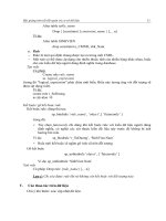
To begin, in the Chen-like model, we will do as Chen originally did and put
the entities in boxes and the show attributes nearby. One way to depict
attributes is to put them in circles or ovals appended to the boxes — see
Figure 2.1
(top and middle). Figure 2.1 (bottom) is an alternative style of
depicting attributes. The alternative attribute style (Figure 2.1
, bottom) is not
as descriptive, but it is more compact and can be used if Chen-like diagrams
become cluttered.
Figure 2.1:
An ER Diagram with Three Attributes
There are several ways of depicting attributes. We have illustrated the
"attribute in a circle" model (Chen-like model) because it is common and
useful. Refer to Figure 2.2
for some alternate models for attributes. There
are benefits to alternate forms for depicting attributes. The standard form of
the Chen-like model with bubbles and boxes is good for conceptualizing; it is
easily changed and very clear as to which attribute goes where. The concise
form (Figure 2.1
[bottom] and other variants in Figure 2.2) is easily created
from the standard form and is sometimes more useful for documentation
when space is a concern.
Figure 2.2:
An ER Diagram with One Entity and Five Attributes,
Alternate Models (Batini, Ceri, Navathe)
Figure 2.1
(middle and bottom) shows an ER diagram with one entity,
STUDENT, and three attributes: name, address, and school. If more
attributes are added to our conceptual model, such as phone and major,
they would be appended to the entity (here, STUDENT is the only entity we
have), as can be seen in Figure 2.3
.
Figure 2.3:
An ER Diagram with One Entity and Five
Attributes
More about Attributes
Attributes are characteristics of entities that provide descriptive details about
the entities. There are several different kinds of attributes: simple or atomic,
composite, multi-valued, and derived. The properties of an attribute are its
name, description, format, and length, in addition to its atomiticity. Some
attributes may be considered unique identifiers for an entity. This section
also introduces the idea of a key attribute, a unique identifier for an entity.
The Simple or Atomic Attribute
Simple or atomic attributes cannot be further broken down or subdivided,
hence the notion "atomic." One can examine the domain of values
[2]
of an
attribute to elicit whether an attribute is simple or not. An example of a
simple or atomic attribute would be Social Security number, where a person
would be expected to have only one, undivided Social Security number.
Other tests of whether an attribute is simple or atomic will depend entirely on
the circumstances that the database designer encounters — the desire of
the "user" for which the database is being built. For example, we might treat
a phone number attribute as simple in a particular database design, but in
another scenario we may want to divide the phone number into two distinct
parts, that is, the area code and the number. Another example of where the
use of the attribute in the database will determine if the attribute is simple or
atomic is — a birthdate attribute. If we are setting up a database for a
veterinary hospital, it may make sense to break up a birthdate field into
month, day, and year, because it will make a difference in treatment if a
young animal is five days old versus if it is five months or five years old.
Hence, in this case, birthdate would be a composite attribute. For a RACE
HORSE database, however, it may not be necessary to break up a birthdate
field into month/day/year, because all horses are dated only by the year in
which they were born. In this latter case, birthdate, consisting of only the
year, would be atomic.
If an attribute is non-atomic, it needs to be depicted as such on the ER
diagram. The following sections deal with these more complicated,
nonatomic attribute ideas — the composite attribute and the multi-valued
attribute.
The Composite Attribute
A composite attribute, sometimes called a group attribute, is an attribute
formed by combining or aggregating related attributes. The names chosen
for composite attributes should be descriptive and general. The concept of
"name" is adequate for a general description, but it may be desirable to be
more specific about the parts of this attribute. Most data processing
applications divide the name into component parts. Name, then, is called a
composite attribute
or an
aggregate
because it is usually composed of a
first name, a last name, and a middle initial — sub-attributes, if you will. The
way that composite attributes are shown in ER diagrams in the Chen-like
model is illustrated in Figure 2.4
. The sub-attributes, such as first name,
middle initial, and last name, are called
simple
,
atomic,
or
elementary
attributes. The word "aggregate" is used in a different sense in some
database query languages and to avoid confusion, but we will not call
composite attributes "aggregates;" we will use the word "composite."
Figure 2.4:
An ER Diagram with a Composite Attribute —
name
Once again, the test of whether or not an attribute will be composite will
depend entirely on the circumstances that the database designer encounters
— the desire of the "user" for which the database is being built. For example,
in one database it may not be important to know exactly which city or state
or zip code a person comes from, so an address attribute in that database
may not be broken up into its component parts; it may just be called address.
Whereas in another database, it may be important to know which city and
state a person is from; so in this second database we would have to break
up the address attribute into street address, city, state, and zip code, making
the address attribute a composite attribute.
The Multi-Valued Attribute
Another type of non-simple attribute that has to be managed is called a
multi
-valued attribute
. The multi-valued attribute, as the name implies, may
take on more than one value for a given occurrence of an entity. For
example, the attribute school could easily be multi-valued if a person attends
(or has attended, depending on the context of the database) more than one
school. As a counter example, most people go by only one name and hence
the grouping, name, is not multi-valued. The multi-valued attribute called
school is depicted in Figure 2.5
(Chen-like model) as a double oval, which
illustrates the situation where a database will store data about students who
may have attended more than one school. Although we have chosen to
illustrate school as a multi-valued attribute, we do not mean to imply that this
will always be the case in all databases. In fact, the attribute, school, may
well be singly valued in some databases. The idea of school may mean the
current (or just-previous) school as opposed to all schools attended. If the
subjects about whom we are storing data can attend only one school at a
time (and that is what we want to depict), then the attribute, school, may well
be a single-valued attribute.
Figure 2.5:
An ER Diagram with a Multi-Valued
Attribute
Once again, the test of singleversus multi-valued will depend entirely on the
circumstances that the database designer encounters — the desire of the
"user" for which the database is being built. It is recommended that if the
sense of the database is that the attribute school means "current school,"
then the attribute should be called "current school" and illustrated as a
single-valued attribute. In our example, we have a multi-valued attribute in
Figure 2.5
, so the sense of the diagram is that multiple schools can be
recorded for each student.
The Derived Attribute
Derived attributes are attributes that the user may envision but may not be
recorded per se. These derived attributes can be calculated from other data
in the database. An example of a derived attribute would be an age that
could be calculated once a student's birthdate is entered. In the Chen-like
model, a derived attribute is shown in a dashed oval (as shown in Figure
2.5A).
Figure 2.5A:
An ER Diagram with a Derived Attribute —
age
keys
The sense of a database is to store data for retrieval. An attribute that may
be used to find a particular entity occurrence is called a
key
. As we model
our database with the ER models, we may find that some attributes naturally
seem to be keys. If an attribute can be thought of as a unique identifier for an
entity, it is called a
candidate key
. When a candidate key is chosen to be
the
unique identifier, it becomes the
primary key
for the entity.
As an example of keys, suppose we add an attribute called student number
to our STUDENT entity example. We might well consider a student number
to be a unique identifier for the entity — a candidate key because of
uniqueness. Name is often unique, but not necessarily so. Members of the
same class often share last names. Address may or may not be a unique
identifier and hence is not a likely candidate key. Siblings that take classes
together could easily have the same address. The point is that schools often
choose to assign a unique student number to each student in order to be
able to find student records — the sense of a key is to provide a unique way
to find an entity instance (a particular record).
Some schools also choose to record a Social Security number (SSN) as an
attribute. An SSN is also unique and hence a candidate key along with
student number. If both SSN and student number were recorded, then the
designer would have to choose which candidate would be the primary key. In
our case, we choose not to record an SSN. The STUDENT entity with the
unique identifier student number added as a key, is depicted in Figure 2.6
.
Figure 2.6:
An ER Diagram with a Primary Key or Unique Identifier
Attribute
In the Chen-like model, attributes that are
unique identifiers
(candidate
keys) are usually underlined (as shown in Figure 2.6
). A unique identifier can
be an attribute or a combination of attributes. It is not necessary to choose
which candidate key will be the primary key at this point, but one could do
so. When there is only one candidate key, we will generally speak of it as the
primary key, simply because it is obvious that the primary key is a candidate
key. In Figure 2.6
we have also depicted the short form of the ER diagram
(at the bottom) with composite attributes and multi-valued attributes as well
as primary keys. The composite attributes are listed with its component
parts, and the multi-valued attributes are enclosed in parentheses in the
abbreviated form.
Finally, while on the subject of keys, we will have situations in the ER
diagram (in the Chen-like model) where no key is obvious or intended.
Entities that have at least one identified key can be called
strong entities
. In
Chen's (1976) original article, strong entities were called
regular entities
.
Some entities will be discovered which depend on other entities for their
being (and hence their identification). Chen called those entities that rely on
other entities for their existence,
weak entities
.
We will often be able to recognize these weak entities because they may not
have candidate keys, although the actual meaning of a weak entity is "one
that depends on another for existence." As Chen did, we will follow the
Chen-like notation and call such entities
weak entities
— weak because
they will have to depend on some other entity to furnish a unique identifier to
give the entity a reason to be recorded.
Although a weak entity may have a candidate key, it would not be a strong
entity. We depict weak entities in the Chen-like ER diagrams with double
boxes (see Figure 2.7
). For now, we will concentrate on those entities that
have keys, and later we will reconsider situations where no key is obvious.
Figure 2.7:
A Strong and a Weak AUTOMOBILE
Entity
Checkpoint 2.2
1. Describe the basic types of data representation schemas used in
entity–relationship (ER) modeling.
2. What notation is used to diagrammatically show an entity in the Chen-
like model?
3. How do we diagrammatically show attributes in the Chen-like model?
4. How do we show composite attributes in the Chen-like model?
5. Draw an entity representation for the entity "building" with the
attributes building name, occupancy, and whether or not it has an
elevator (yes/no).
6. Embellish the building entity to include the building superintendent's
name (first, middle, and last). Does this have to be a composite
attribute? Why or why not?
7. Embellish the building entity to include the address of the building,
which will be the primary key.
8. Once again, embellish the building entity to include names (and only
the names) of the janitorial staff.
9. Add a multi-valued attribute to the building entity. 10. How many
attributes can an entity have?
[2]
The "domain of values" is the set of values that a given attribute may take
on. The domain consists of all the possible legal values that are permitted on
an attribute. A data type is a broader term used to describe attributes, but
"data type" includes the idea of what operations are allowable. Since
database people are usually more concerned about storage and retrieval,
database "data types" usually just focus on the "domain of values."
English Description of the Entity
Now that we have an entity with attributes, we want to prepare the first
feedback to the user — the English description. Users will not likely want to
study the entity diagram but they well might want to hear what you, the
analyst, think you heard. For an English description, we will use a
"structured" English grammar and substitute the appropriate information from
the entity diagram.
The Method
The guideline for the structured English for single entities is as follows.
Let
Entity
be the name of the entity and
att(j)
be the attributes. The order of
the attributes is not important, so j = 1, 2,
…
is assigned arbitrarily. Suppose
that there are
n
attributes so far. The generalized English equivalent of our
diagram is:
The Entity
This database records data about
Entity
. For each
Entity
in the
database, we record
att(1)
,
att(2)
,
att(3)
,
…
,
att(n)
.
The Attributes
For
atomic
attributes, a(j):
For each
Entity
, there always will be one and only one
att(j)
for
each
Entity
. The value for
att(j)
will not be subdivided.
For
composite
attributes, a(j):
For each
Entity
, we will record
att(j)
, which is composed of
x, y,
z
…
,
(x, y, z)
are the component parts of
att(j)
.
For
multi-valued
attributes, a(j):
For each
Entity
, we will record
att(j)
's. There may be more than one
att(j)
recorded for each
Entity
.
For
derived
attributes, a(j):
For each
Entity
, there may exist
att(j)
's, which will be derived from
the database.
The Keys
For the key(s):
a. More than one candidate key (strong entity):
For each
Entity
, we will have the following candidate keys:
att(j),
att(k)
,
…
, [where
j
,
k
are candidate key attributes]
b. One candidate key (strong entity):
For each
Entity
, we will have the following primary key:
att(j)
c. No candidate keys (weak entity):
For each
Entity1
, we do not assume that any attribute will be
unique enough to identify individual entities without the
accompanying reference to
Entity2
, the owner Entity.
[3]
d. No candidate keys (intersecting entity):
For each
Intersecting Entity1
, we do not assume that any
attribute will be unique enough to identify individual entities
without the accompanying reference to
Entity2
, the owner Entity.
[3]
The details of the weak entity/strong entity relationship will become clearer
as we introduce relationships in Chapter 3
.
ER Design Methodology
Step 2: Use structured English for entities, attributes, and keys to
describe the database that has been elicited.
Step 3: Show some sample data.
Sample data also helps describe the database as it is perceived.
Examples
We will now revisit each of our figures and add an English description to
each one. First, reconsider Figure 2.3
. There are no multi-valued or
composite attributes.
Entity
= STUDENT,
att(1)
= name,
att(2)
= school, etc.
(j assigned arbitrarily). The English "translation" of the entity diagram using
the above templates would be:
The Entity
This database records data about STUDENTS. For each
STUDENT in the database, we record a name, a school, an
address, a phone number, and a major.
The Attributes
For each name, there always will be one and only one name
for each STUDENT. The value for name will not be subdivided.
For each major, there always will be one and only one major
for each STUDENT. The value for major will not be subdivided.
(Note that in Figure 2.3
we did not divide name.)
For each address, there always will be one and only one
address for each STUDENT. The value for address will not be
subdivided.
For each school, there always will be one and only one school
for each STUDENT. The value for school will not be
subdivided.
For each phone number, there always will be one and only one
phone number for each STUDENT. The value for phone
number will not be subdivided.
The Keys
For each STUDENT, we do not assume that any attribute will
be unique enough to identify individual entities. (Remember
that we are describing Figure 2.3
.)
Sample Data
In addition to the above descriptions, some sample data is often very helpful
in showing the user what you have proposed:
STUDENT
name major address school phone number
Now consider Figure 2.4. This figure has a composite attribute — name. The
English "translation" of this entity diagram would be as follows:
The Entity
This database records data about STUDENTS. For each
STUDENT in the database, we record a name, a school, and
an address.
The Attributes
For each name, there always will be one and only one name
for each STUDENT. The value for name will be subdivided into
a first name, a last name, and a middle initial.
For each address, there always will be one and only one
address for each STUDENT. The value for address will not be
subdivided.
For each school, there will be one and only one school for each
STUDENT. The value of the school will not be subdivided.
The Keys
For each STUDENT, we do not assume that any attribute will be unique
enough to identify individual entities.
Sample Data
Next consider Figure 2.5. This figure has a composite as well as a multi-
valued attribute. The English "translation" of this entity diagram would be as
Smith Cosc 123 4th St St. Helens 222–2222
Jones Acct 222 2nd St PS 123 333–3333
Saha Eng 284 3rd St Canton 345–3546
Kapoor Math 20 Living Cr High 435–4534
STUDENT
name.first name.last name.mi school address
Richard Earp W U. Alabama 222 2nd St
Boris Backer
Heidleburg 333
Dreistrasse
Helga Hogan H U. Hoover 88 Half Moon
Ave
Arpan Bagui K Northern
School
33 Bloom Ave
Hema Malini
South Bend 100
Livingstone
follows:
The Entity
This database records data about STUDENTS. For each
STUDENT in the database, we record a name, a school, and
an address.
The Attributes
For each name, there always will be one and only one name
for each STUDENT. The value for name will be subdivided into
a first name, a last name, and a middle initial.
For each address, there always will be one and only one
address for each STUDENT. The value for address will not be
subdivided.
For each STUDENT, we will record schools. There may be
more than one school recorded for each student.
The Keys
For each STUDENT, we do not assume that any attribute will
be unique enough to identify individual entities.
Sample Data
Consider Figure 2.6. This figure has a composite, multi-valued, as well as
key attribute. The English "translation" of this entity diagram would be as
follows:
The Entity
This database records data about STUDENTS. For each
STUDENT in the database, we record a name, schools, an
address, and a student number.
The Attributes
STUDENT
name.first name.last name.mi school address
Richard Earp W U. Alabama,
Mountain
222 2nd St
Boris Backer
Heidleburg,
Volcano
333
Dreistrasse
Helga Hogan H U. Hoover, St.
Helens
88 Half
Moon Ave
Arpan Bagui K Northern
School
33 Bloom
Ave
Hema Malini
South Bend 100
Livingstone
For each name, there always will be one and only one name
for each STUDENT. The value for name will be subdivided into
a first name, a last name, and a middle initial.
For each address, there always will be one and only one
address for each STUDENT. The value for address will not be
subdivided.
For each STUDENT, we will record schools. There may be
more than one school recorded for each student.
The Keys
For each STUDENT, we will assume that there is an attribute
— student number — that will be unique enough to identify
individual entities.
Finally, consider Figure 2.7
(top). This figure shows a strong entity. We will
combine the grammar a little to keep the methodology from being overly
repetitive. The English "translation" of this entity diagram would be as
follows:
The Entity
This database records data about AUTOMOBILEs. For each
AUTOMOBILE in the database, we record a make, body style,
year, color, and vehicle-id.
The Attributes
Each AUTOMOBILE will have one and only one make, body
style, year, color, and vehicle-id. None of these attributes will
be subdivided.
The Keys
For each AUTOMOBILE, we assume that attribute vehicle-id
will be unique enough to identify individual entities.
Figure 2.7
(bottom) shows a weak entity. The only difference between the
strong and weak entity description involves the key phrase, which may not
exist in the weak entity.
Figure 2.8
shows a relationship between two entities, an AUTOMOBILE and
a STUDENT. The concept of relationships is discussed in more detail in
Chapter 4
.
Figure 2.8:
An ER Diagram of the STUDENT-AUTOMOBILE
Database
Our methodology has evolved as follows:
ER Design Methodology
Step 1: Select one primary entity from the database requirements
description and show attributes to be recorded for that entity. Label
key if appropriate.
Step 2: Use structured English for entities, attributes, and keys to
describe the database that has been elicited.
Step 3: Show some data.
Mapping the Entity Diagram to a Relational Database
Having illustrated the ideas of the entity and the attribute, we now turn to a
semi-physical realization of the concepts. We say "semi-physical" because
we are really not concerned with the actual physical file that is stored on a
disk, but rather we are concerned with placing data into relational tables that
we will visualize as a physical organization of data. Basically, a relational
database is a database of two-dimensional tables called "relations." The
tables are composed of rows and columns. The rows are often called
tuples
and the columns,
attributes
. In relational databases, all attributes (table
columns) must be atomic and keys must not be null. In addition, in relational
databases, the actual physical location of the data on a disk is not usually
necessary to know.
The process of converting an ER diagram into a database is called
mapping
. We concern ourselves only with the relational model and hence,
as the chapters in this book develop, we will consider mapping rules to map
ER diagrams into relational databases.
We start with a rule to map strong entities:
M1 — for strong entities: develop a new table (relation) for
each strong entity and make the indicated key of the
strong entity the primary key of the table. If more than one
candidate key is indicated on the ER diagram, choose one
for the primary key.
Next, we must map the attributes into the strong entity. Mapping rules are
different for atomic attributes, composite attributes, and multi-valued
attributes. First, we present the mapping rule for mapping atomic attributes:
M1a — mapping atomic attributes from an entity — for
entities with atomic attributes: map entities to a table by
forming columns for the atomic attributes.
[4]
A relational database realization of the ER diagram in Figure 2.3
with some
data would look like this:
The entity name, STUDENT, would be the name of the relation (table). The
attributes in the diagram become the column headings. The actual table with
data, a realization of a relation, is provided as an example of the type of data
you might expect from such a relation. The ordering of the columns is
irrelevant to relational database as long as once the ordering is chosen, we
stay with it.
What about the composite and multi-valued attributes? As mentioned above,
STUDENT
name phone school address major
Jones 932–5100 U. Alabama 123 4th St Chemistry
Smith 932–5101 U. Mississippi 123 5th St Math
Adams 932–5102 LSU 123 6th St Agriculture
Sumon 435–0997 UWF 11000 Univ Comp Sc
Mala 877–0982 Mount Union North Canton History