the best damn cisco internetworking book period phần 2 pps
Bạn đang xem bản rút gọn của tài liệu. Xem và tải ngay bản đầy đủ của tài liệu tại đây (1.84 MB, 117 trang )
Cisco Technologies, Routers, and Switches • Chapter 1 73
Hardware is Lance, address is 00e0.b05a.d998 (bia 00e0.b05a.d998)
Internet address is 192.168.123.50/24
MTU 1500 bytes, BW 10000 Kbit, DLY 1000 usec,
reliability 255/255, txload 1/255, rxload 1/255
Encapsulation ARPA, loopback not set
Keepalive set (10 sec)
ARP type: ARPA, ARP Timeout 04:00:00
Last input 00:00:00, output 00:00:00, output hang never
Last clearing of "show interface" counters never
Input queue: 0/75/0/0 (size/max/drops/flushes); Total output drops: 0
Queueing strategy: fifo
Output queue :0/40 (size/max)
5 minute input rate 0 bits/sec, 0 packets/sec
5 minute output rate 0 bits/sec, 0 packets/sec
93866 packets input, 13802455 bytes, 0 no buffer
Received 47471 broadcasts, 0 runts, 0 giants, 0 throttles
0 input errors, 0 CRC, 0 frame, 0 overrun, 0 ignored
0 input packets with dribble condition detected
234089 packets output, 24304032 bytes, 0 underruns
0 output errors, 2 collisions, 31 interface resets
0 babbles, 0 late collision, 19 deferred
0 lost carrier, 0 no carrier
0 output buffer failures, 0 output buffers swapped out
Increasing Efficiency by Using Shortcuts
Until now, we have purposefully and completely written out the entire string when entering
commands. Cisco software does support a shorthand version of its command syntax.You can
enter only a partial portion of the command as long as you provide enough for the IOS to rec-
ognize it. For example, you can enter copy run star, which the router will recognize to mean
copy running-configuration startup-configuration.
The following example uses shortcuts rather than spelling out the full command. In this
example, we are entering privileged mode and configuring an IP address for the Ethernet 0
interface. Our final task is copying the running configuration to NVRAM:
6Router-1>en
6Router-1# conf t
Enter configuration commands, one per line. End with CNTL/Z.
6Router-1(config)# int e0
6Router-1(config-if)# ip add 10.1.1.1
6Router-1(config-if)# ex
6Router-1(config)# ^Z
6Router-1(config)# copy run star
www.syngress.com
253_BDCisco_01b.qxd 10/15/03 9:20 AM Page 73
74 Chapter 1 • Cisco Technologies, Routers, and Switches
In the preceding example, we entered privileged mode by entering en instead of typing
enable, then entered configuration mode by entering config t, which the router recognized as
configure terminal. We next entered interface configuration mode by typing int e0, which the
router recognized as interface Ethernet 0. We then configured an IP address by using the IP
add command. After existing with ex for exit, we copied running configuration NVRAM with
copy run star for the command copy running-config startup-config.
The rule for shortcuts is that you can reduce a command as long as it is unique from other
commands. For example, you could not reduce disable to DI, because disconnect also starts with
DI, so you would need to use DISA, and conversely, disconnect would need to be DISC. If you
do not enter enough information to make the command unique, you will be met with an error
stating % Ambiguous command:.This indicates that you need to type more of the command.
The auto-complete feature automatically completes a command when you simply press the
Tab key.You must enter enough information for the command to be unique or it will not work.
The following code example demonstrates this feature. In this example you are trying to enter
the configure terminal command.You start by trying to enter con, but this does not work
because both the configure and connect commands start with ”“con,” so you have to enter
enough information to make it unique by entering conf.You follow this by t and hit the Tab
key to get the terminal word to appear:
6Router-1# con
6Router-1# conf
6Router-1# configure t
6Router-1# configure terminal
A set of shortcuts is also available with specific keystrokes to move the cursor and perform
other actions.
■
CTRL + A Move to the beginning of a line
■
CTRL + E Move to the end of a line
■
CTRL + R Redisplay a line
■
CTRL + K Erase all from cursor to end of line
■
CTRL + X Erase all from cursor to beginning of line
■
CTRL + W Erase a Word
■
CTRL + X Exit Configuration Mode
The autocommand Feature
Cisco routers can automate tasks that are associated with terminal lines using the autocommand
option. autocommand allows the execution of any EXEC mode command when a connection
is established to a terminal line.This is convenient when you want to control the operating char-
acteristics of a dial-in modem.
www.syngress.com
253_BDCisco_01b.qxd 10/15/03 9:20 AM Page 74
Cisco Technologies, Routers, and Switches • Chapter 1 75
For example, if you want to have users dial in to an access server and connect to a UNIX
host, this can be done automatically as soon as the session is established. In the following
example, the autocommand feature establishes a session to a UNIX host with an IP address of
192.168.1.1.
line vty 129
autocommand connect 192.168.1.1
The autocommand feature can issue any EXEC command, not just Telnet sessions.You can
configure the autocommand feature for remote support by technical staff; if you want them to
be able to dial in and view the TCP/IP routing table, you can use the autocommand feature to
automate this process, as illustrated in the following example:
line vty 129
autocommand show ip route
Menus
Menus can be configured within Cisco IOS to provide users connecting to a router with an
easy-to-use interface. Users do not need to learn the underlying command syntax to accomplish
basic tasks.The following is an example of a basic menu that users can utilize to access network
services.
Welcome to the Corporate Network
Type a number to select an option;
Type 9 to exit the menu.
1 Connect to VMS (LAT)
2 Connect to the IBM Mainframe (TN3270)
3 Read E-Mail
4 Start PPP
Exit the Menu
When users connect to this router, this is the menu they see.The following is the command
structure for the menu shown previously:
menu Basic title ^C
Welcome to the Corporate Network
Type a number to select an option;
Type 9 to exit the menu.^C
menu Basic text 1 Connect to VMS (LAT)
menu Basic command 1 LAT CENTRAL
menu Basic text 2 Connect to the IBM Mainframe (TN3270)
menu Basic command 2 tn3270 mainframe
menu Basic text 3 Read E-Mail
menu Basic command 3 telnet mail.corp.com
menu Basic text 4 Start PPP
www.syngress.com
253_BDCisco_01b.qxd 10/15/03 9:20 AM Page 75
76 Chapter 1 • Cisco Technologies, Routers, and Switches
menu Basic command 4 ppp
menu Basic text 9 Exit the Menu
menu Basic command 9 exit
menu Basic clear-screen
menu Basic default 3
Menus can have a title that is displayed when the menu starts, which is created with the
menu name title delimiter command.The delimiter is the ASCII character the router will use to
signify the end of the character string used for the title.Typically, you would not want to use a
standard letter, because that letter may appear in the text you enter.A rarely used character such
as a tilde (~) can save you quite a bit of frustration.
To create the entries the users will see when the menu is executed, you use the menu name
text item text command.
■
Item The number that you want to appear next to the text.
■
Number The number that the users will use to invoke that particular selection.
It is important to note that menus can only have 18 entries, but Cisco has built in the ability
to create submenus. When all entries have been created, configure the commands that will be
executed when a user picks a menu option.To do this, you use the menu name command item
text format.The item is the number of the command you want to use, while the text is the actual
command executed. It is important to note that the value placed in the text portion corresponds
exactly to the command a user would enter if they were connected to the router with no menu
system.
You also have some additional controls over the way a menu is displayed and operates.
Commands such as menu title clear-screen make the router insert 24 new lines, which effectively
clears the screen. It is important to note that the menu system default is a standard “dumb” terminal
that only displays text in a 24-line-by-80-column format. With the use of submenus, a very com-
plex and feature-rich menu system can be created. It is important to note that all menus should
have an exit menu option, otherwise, you can get stuck in a menu loop with no way to exit.
CATOS Command
Syntax and Basic Configuration
There are several ways to configure a Cisco Catalyst switch. We do not cover configuration via
menu selection or via Web interface, as they provide enough structure and information to guide
you through the process of configuration. Instead, we focus on CLI configuration, which is more
complex and has more parameters with which to contend.
Our discussion is complicated by the fact that the OS for the Catalyst line has and is still
evolving into the more familiar Cisco IOS syntax (variously known as integrated or native
mode). However, there is still a large base of switches that have the “original” Catalyst OS on
them, known by its legion of trusty set commands. Further compounding the confusion of what
commands to use are semi-evolved versions of the Catalyst OS that contain commands that
appear to be a mix of IOS and CATOS commands. We discuss and provide examples of using
both types of commands to accomplish the same task.
www.syngress.com
253_BDCisco_01b.qxd 10/15/03 9:20 AM Page 76
Cisco Technologies, Routers, and Switches • Chapter 1 77
You console or Telnet (if networking is configured) to switch, and execute the necessary
commands at the prompt.The CATOS automatically saves the changes as you make; the CAT
IOS does not.
Configuring Network Parameters
If you want to manage your switch remotely (Telnet, SNMP, and other means that require an IP
address), you need to configure the network parameters of that switch, including an address,
mask, and default gateway at a minimum.There are currently three types of management inter-
faces used by the CATOS for management:
■
SL0 SLIP-based connection to the console port on the SE module for out-of-band
management.This can be used for remote dial-in sessions to the switch via a modem.
■
SC0 A logical in-band management interface assigned to VLAN1 by default, but can
be assigned to any VLAN. Doing so will make it reachable provided that you have a
route to and from its assigned VLAN.
■
ME1 A reserved, dedicated Ethernet port for out-of-band management of the switch. It
is not assigned to any VLAN, but exists as a “stand alone” network port.
The following shows how to configure these management interfaces. Notice that since we
are using addresses from the same subnet for SC0 and ME1, we downed one interface in favor of
the other in order to operate. We also, for fun, put SC0 in VLAN999 before we downed it, just
to show that we are the boss of this switch and can put the SC0 interface in any VLAN we want.
We also identified the default gateway.
set interface sc0 1 10.11.20.111/255.255.254.0 10.11.21.255
set int sc0 999
interface sc0 vlan set.
set interface sc0 down
set interface me1 10.11.20.110 255.255.254.0 10.11.21.255
set ip route default 10.11.20.1
On a switch with IOS, the above interfaces do not exist. Instead, you specify and address a
VLAN on the switch as follows. While this example shows the management interface in VLAN1,
it can actually be in any VLAN.
interface vlan 1
ip address 10.11.20.110 255.255.254.0
ip default-gateway 10.11.20.1
Once you have configured networking on the Catalyst, you can then Telnet in or perform
other network tasks on the switch.
www.syngress.com
253_BDCisco_01b.qxd 10/15/03 9:20 AM Page 77
78 Chapter 1 • Cisco Technologies, Routers, and Switches
Securing the Switch
To protect the Catalyst, you can use local authentication, or authenticate via a TACACS,
RADIUS, or Kerberos. In our example, we show both methods.To use local authentication with
CATOS, specify:
set password cisco
set enablepass cisco
To use TACACS+:
set authentication enable tacacs all primary
set authentication login tacacs all primary
set tacacs server 10.11.20.20 primary
With Catalyst IOS, the same thing is accomplished with the following series of commands.
enable password cisco
enable secret cisco
vity 0 4
password cisco
aaa new-model
aaa authentication login default
tacacs-server host 10.11.20.20
Creating VLANs
VLANs define and contain the broadcasts for a network.The first step in VLAN creation (regard-
less of which OS is being used) must be to define the Virtual Trunking Protocol (VTP) domain.
VTP is used between switches to exchange information about the VLANs that each services.
Each switch can belong to only one VTP domain at a time; information is only exchanged by
switches in the same VTP domain. Without VTP, switches would not be able to share informa-
tion about their VLANs.A switch can serve in one of the following VTP domains.
■
Server Can create and modify VLANs, which are advertised throughout the VTP
domain.This is the default mode.
■
Client Does not originate or modify any VLANs; receives information from the server.
■
Transparent Does not uses or depend on VTP, nor are VLANs created on it sent to
other switches in the VTP domain. Essentially turns off VTP on the switch.
In VTP transparent mode, VLAN configurations are saved in nonvolatile memory, but they
are not advertised to other switches.To define VLANs, execute the following series of commands.
The set vlan command is used to add ports to a VLAN.
www.syngress.com
253_BDCisco_01b.qxd 10/15/03 9:20 AM Page 78
Cisco Technologies, Routers, and Switches • Chapter 1 79
# vtp
set vtp domain BEST_CISCO_BOOK
set vlan 999 name BEST_CISCO_BOOK
set vlan 999 4/3
The native mode equivalent is:
vlan database
vtp domain BEST_CISCO_BOOK
vlan database
vlan 999 mtu 1500
interface fa4/3
switchport mode access
switchport access vlan 999
Port Configuration
You can change the parameters of a port such as its speed, duplex settings, and other parameters
as shown. Port security allows you to restrict what MAC addresses may be connected to a partic-
ular port: you can simply enable it with no parameters and the first detected MAC address will
be the only one allowed on this port or you can specify MAC addresses (up to 1024) manually.
The other port commands used in this section are self explanatory by their names. When port
security is enabled, the port cannot be a trunk or have SPAN enabled,
set port security 4/3 enable aa-bb-cc-dd-ee-ff-11
set port speed 4/3 100
set port name 4/3 Best_Cisco_Port
set port duplex 4/3 auto
The CAT IOS version of the same commands are:
interface fastethernet4/3
description Best_Cisco_Port
speed 100
duplex auto
port security
The port security command is slightly different in the IOS for the Catalyst in that you
cannot specify a MAC address.
www.syngress.com
253_BDCisco_01b.qxd 10/15/03 9:20 AM Page 79
80 Chapter 1 • Cisco Technologies, Routers, and Switches
Enabling Trunking
Trunking is the use of switch ports to transport multiples VLANs, often with several ports
grouped together with Etherchannel to provide redundancy and the increased bandwidth neces-
sary to transport multiple networks.The process of configuring a port as trunk is simply a matter
of identifying it as such.
Cisco supports two types of trunking. Cisco developed the InterSwitch Link (ISL) trunking
protocol for its switches.The IEEE developed 802.1q as a vendor-independent standard for
trunking. ISL can only be used on Cisco products, while 802.1q can enable interoperation with
non-Cisco switches.Auto-negotiation of a trunking protocol is possible (for example, set trunk
4/11 desirable negotiate). Since we are firm believers in vendor-independent standards, we
configure for 802.1.q in our examples.
We clarify the parameters and options associated with the various trunk commands.
set trunk mod_num/port_num [on | desirable | auto | nonegotiate] dot1q isl negotiate
■
On Converts ports to a trunk.
■
Off Converts trunk to a regular port.
■
Desirable Converts port to trunk if neighbor is configured for trunking.
■
Auto Port is converted to trunk if neighbor trunking state is on or desirable.
■
Nonnegotiate Neighbor trunk has to be manually configured.
■
ISL Specifies ISL as the trunking protocol.
■
Dot1q Specifies 802.1q as the preferred trunking protocol.
■
Negotiate Will negotiate which trunking protocol to use with a neighbor.
By default, when you define a trunk, all VLANs will be transported over it. If this is not
desirable, you can remove all VLANs from the trunk with the clear trunk command, and then
add only those VLANs you want to trunk with the set trunk x/x #### where x/x is the port
being trunked and #### is the number of the VLAN to be transported.
The following example shows how to configure a trunk on a switch using CATOS commands.
set trunk 4/1-2 on dot1q
Complete this command on the neighboring switch, and you will have an 802.1q trunk
transporting all VLANs.You can confirm the status of your trunking efforts with:
Syngress_4006 (enable) show trunk
* - indicates vtp domain mismatch
Port Mode Encapsulation Status Native vlan
4/1 nonegotiate dot1q trunking 1
4/2 nonegotiate dot1q trunking 1
www.syngress.com
253_BDCisco_01b.qxd 10/15/03 9:20 AM Page 80
Cisco Technologies, Routers, and Switches • Chapter 1 81
Port Vlans allowed on trunk
4/1 1-1005
4/2 1-1005
Port Vlans allowed and active in management domain
4/1 1,998-999
4/2 1,998-999
Port Vlans in spanning tree forwarding state and not pruned
4/1 1,999
4/2 1,999
Trunking on a Catalyst IOS switch is configured through the process shown.The ports to be
used for trunking are configured as pure Layer 2 interfaces.The switchport command config-
ures the port to be a trunk, as well as specifying parameters such as 802.1q.
interface FastEthernet4/1
no ip address
switchport
switchport trunk encapsulation dot1q
switchport mode trunk
interface FastEthernet4/2
no ip address
switchport
switchport trunk encapsulation dot1q
switchport mode trunk
View your trunk port details with show interface fastethernet 4/1 trunk, for example.
Networking Monitoring and Packet Capture
All Cisco Catalyst switches have the ability to copy traffic inbound and outbound on any port to
another port for monitoring and analysis.This feature is known as Switch Port Analyzer (SPAN)
is useful for determining what traffic in what amounts and types is transiting a particular switch
port.
On a CATOS switch, span is enabled and disabled with the following commands. If you are
going to use SPAN regularly, ensure that the first SPAN command you learn is set span disable
all to turn off all SPAN operations.
set span disable [dest_mod/dest_port | all]
www.syngress.com
253_BDCisco_01b.qxd 10/15/03 9:20 AM Page 81
82 Chapter 1 • Cisco Technologies, Routers, and Switches
set span {_mod/src_ports | src_vlan } {dest_mod/dest_port} [rx | tx | both]
[filter {vlan}][inpkts {enable | disable}] [learning {enable | disable}]
[multicast {enable | disable}] [create]
For example, to monitor all traffic from port 3/1 to monitoring port 4/1, you would execute
the following command. By default, traffic transmitted and received on the port is captured.
set span 3/1 4/1
The CAT IOS equivalent is provided here.
{ no } port monitor [interface | vlan vlan-id]
Notice that you execute this command on the monitoring interface by identifying the source
interface or VLAN, as shown.
interface Fastethernet4/1
port monitor fa3/1
You are Not Alone—Resources
for Cisco Hardware and Software
The configuration of Cisco products can become quite complex as your network grows, or the
demand for new services increases. It can be a very delicate balancing act to get the mix of hard-
ware and software working exactly as needed. Complications can arise as you add new hardware,
turn on new features, or bugs are discovered at the last minute. When that happens, knowing
where to go for assistance can be immeasurably invaluable, especially when it is just you at 2:00
AM in the morning needing a solution by 6AM and it is something that you have never seen
before.The following are resources that can be of great assistance for whatever problems you may
encounter, or if you need to master new hardware, software, or features in general.
Cisco Technical Support—General
Your starting point for obtaining assistance from Cisco is the Technical Support page at
www.cisco.com/en/US/partner/support/index.html is shown in Figure 1.32.
www.syngress.com
253_BDCisco_01b.qxd 10/15/03 9:20 AM Page 82
Cisco Technologies, Routers, and Switches • Chapter 1 83
You will need a Cisco Connection Online (CCO) account to access this page which pro-
vides links to a variety of support tools, several of which we discuss next.
CCO
Obtaining a CCO account provides you with your portal to many aspects of the Cisco support
systems. In fact, it is your first step.There are two levels of CCO access: guest and registered
user.You can find the CCO datasheet at: www.cisco.com/warp/public/cc/serv/mkt/sup/tsssv/
opmsup/ctspco/cco02_ds.htm.
Registering as a guest provides you with the following benefits (this information is taken
from the CCO data sheet provided at the URL previously provided.
■
Cisco worldwide contacts and events calendar
■
Press releases
■
Packet, Cisco’s user’s magazine
■
Product catalogue, brochures, and announcements
■
Training and seminar schedules
■
General service and support information
■
Cisco MarketPlace and electronic Commerce Agents
Notice that guest access does not give you any special assistance access. For that, you need to
become a registered user.This requires the purchase of a support contract, such as SmartNet or
Comphrensive, or sponsorship by a Cisco partner. Becoming a registered user provides the fol-
lowing benefits (as taken from the Cisco CCO datasheet).
www.syngress.com
Figure 1.32 Cisco Technical Support
253_BDCisco_01b.qxd 10/15/03 9:20 AM Page 83
84 Chapter 1 • Cisco Technologies, Routers, and Switches
■
All Guest-level information
■
Interactive user applications
■
Networking Professionals Connection, a powerful search engine for Cisco’s Q&A
database
■
Technical Assistance Center (TAC) (Case Open, Case Query, Case Update)
■
Bug Toolkit
■
Bug Navigator, finds known bugs
■
Bug Alert, proactively alerts customers of possible bugs and fixes
■
Software Upgrade Planner
■
Software updates and upgrades
■
Product bulletins
■
Software release notes
■
Technical tips and references
■
Known problem and workaround reports
■
Installation notes and case studies
■
Partner sales information
■
Order status checking
■
Pricing and configuration of Cisco products
Several of these support options bear special mention, such as the TAC and the Network
Professionals Connection.
TAC
The TAC provides 24 x 7 x 365 support for all manner of questions and problems. Access to the
TAC is limited to registered users. Engineers who work for Cisco are responsible for fielding the
issues sent to the TAC. Cases can be opened or queried via the Web (www.cisco.com/tac), e-mail
(), or telephone (Asia-Pacific: +61 2 8446 7411; Australia: 1 800 805 227; EMEA:
+32 2 704 55 55 or USA: 1 800 553-2447).
The general process is that you open a case by providing the details of your problem. Cisco
will then assign a case number and priority, and maintain a record of efforts (including suggested
solutions and any information/feedback you provide.)
To ensure the timeliness of responses by severity and in some cases, by the weight of your
contract, Cisco assigns each case the following proprieties.
■
Priority 1 (P1) Critical and merits round the clock effort until resolved.
■
Priority 2 (P2) Severe degradation of operations. Normal business hours commitment
until resolved.
www.syngress.com
253_BDCisco_01b.qxd 10/15/03 9:20 AM Page 84
Cisco Technologies, Routers, and Switches • Chapter 1 85
■
Priority 3 (P3) Operations are impaired, but your core business is unimpeded.
Normal business hours commitment.
■
Priority 4 (P4) Assistance needed with Cisco hardware and software, but there is little
or no impact on your core business. Catch as catch can commitment.
In addition to the TAC, you can also post informally to the Network Professional
Connection (NPC) (which replaced the Open Forum that served the same function).
NPC
The NPC consists of engineers and technicians (Cisco and non-Cisco) who voluntarily provide
answers and information to posted questions. It is essentially a free-for-all newsgroup where
anyone with questions and answers can post.There are a variety of subject areas as shown in
Figure 1.33.
The only requirement for using NPC is that you need a registered user CCO account. In
addition to posting questions, you can also avail yourself of the TechTalks, which are online semi-
nars conducted by experts on a variety of topics. NPC is useful for obtaining answers to non-
critical questions concerning Cisco products, or particular features. Since this is a voluntary effort,
answers to your questions are not subject to a timed schedule, though in this author’s opinion, the
responses have been fairly rapid for a voluntary effort. NPC is meant to be more of a discussion
forum, rather than a technical support tool.
Software Advisor
Cisco provides the Software Advisor (SA) tool to help you select the correct software version and
feature set that will satisfy your requirements. Figure 1.34 shows the opening screen for SA.
www.syngress.com
Figure 1.33 NPC
253_BDCisco_01b.qxd 10/15/03 9:20 AM Page 85
86 Chapter 1 • Cisco Technologies, Routers, and Switches
With SA, you can search by features to find the image versions that contain the features that
you need. Alternately, you can determine what features are supported by a particular version. As
shown in the figure, you can compare two images to determine which is most appropriate.The
SA can help you select an image that is comparative with your target hardware platform, with
just the right amount of features. Prior to ordering or downloading an image, use SA to ensure
you are selecting the correct one. A complement to SA is the Feature Navigator, which allows
you to browse feature by feature to determine what versions support particular commands and
parameters. Once you have determined what version you need using either method, you are
ready to download it from the Software Center.
Software Center
Cisco believes in making life easy for its customers.To that end, it makes almost all software
images for all products downloadable to registered CCO account holders.This is a very cus-
tomer-friendly and convenient feature that allows customers who have the appropriate contract
and legal right (via purchase, contracts, and so on) to download image software.The full value of
the Software Center becomes apparent when an upgrade to a new version becomes necessary:
rather than ordering and waiting for media with the image to arrive via traditional shipping
methods where it can be mangled by an indifferent and uncaring delivery person, it can be
downloaded in a matter of minutes, which significantly reduces downtime.
www.syngress.com
Figure 1.34 SA
253_BDCisco_01b.qxd 10/15/03 9:20 AM Page 86
Cisco Technologies, Routers, and Switches • Chapter 1 87
You must hold a contract that entitles you to the software you want to download, or have
purchased the software you want to download. If you do not satisfy the conditions in the license,
you are not entitled legally to download this software.
Selecting and downloading the software is a simple matter of pointing and clicking your way
through a series of Web pages until you have selected the appropriate version, feature, and plat-
form, as shown in Figure 1.35.
Here we have arrived at the page to download IOS version 12.3.1a with the IP Plus feature
for the Cisco 2500 series of routers.This is a LD release that has not achieved GD status.
Clicking the “I Agree” button will force you to first agree to the legal restrictions for this image,
and then you can download and install.
So far, we have discussed Cisco tools that you have at your disposal.There is one non-Cisco
resource that we need to highlight that has helped many an engineer stuck in a tight spot.
Groupstudy.com
Groupstudy.com is a premier collection of newsgroups devoted to networking topics, especially
the study of Cisco topics launched in 1998 by Paul Borghese after he achieved his CCIE.
GroupStudy is devoted to helping engineers achieve various Cisco certifications such as CCNA,
CCNP, CCIE, and others. It has evolved into an important force in the Information Technology
(IT) community. It is an excellent resource for posting questions, sharing information, and
learning from the most experienced and intelligent people in the business. Contributors and users
www.syngress.com
Figure 1.35 IOS Upgrade Planner
253_BDCisco_01b.qxd 10/15/03 9:20 AM Page 87
88 Chapter 1 • Cisco Technologies, Routers, and Switches
include newly minted CCNAs, CCIEs, respected authors, and professionals from all walks of life.
Figure 1.36 shows the Groupstudy homepage (www.groupstudy.com).
Over time, specialized topic groupstudies have resulted from the specialization of various cer-
tifications such as CCIE R&S, Security, and C&S labs.There is also an employment Groupstudy
devoted to job information, such as available positions, to discussing any employment-related
topic such as salary negotiations, career changes, and so on. Any newsreader or e-mail client can
be used to browse and post to Groupstudy.com.You can also elect to subscribe, which will result
in Groupstudy postings being sent your e-mail address.
Summary
Networking has grown from its academic and military origins to become a pervasive factor in
the lives of organizations and individuals. We discussed networking stripped to its barest essentials
to provide you with the information you need to deploy and maintain robust networks.The OSI
model is a guidepost for networking, from development to troubleshooting; using its layers to
structure your efforts can increase your effectiveness.
Networks can be distinguished by the spatial area that they service. LANs tend to cover a
small area, such as a building or small campus. WANs provide the technology necessary to inter-
connect islands of isolated networks.
www.syngress.com
Figure 1.36 Groupstudy
253_BDCisco_01b.qxd 10/15/03 9:20 AM Page 88
Cisco Technologies, Routers, and Switches • Chapter 1 89
Cisco provides many solutions that have become integral to networking. LAN switches provide
connectivity to end devices such as workstations and servers. Routers are more concerned deliv-
ering traffic to its final destination via the use of network addresses such as that provided by IP.
All Cisco devices can be configured in a number of ways.The simplest and cleanest is the
CLI, though it requires knowledge of the command syntax and parameters. On many Cisco
products, you can use other means such as SNMP and HTTP to complete your configuration.
There are also products such as ConfigMaker that will guide you through the process of creating
your configuration.
When all of your devices are working as they should, all is well in the world. However, when
problems occur (and they will), you may need to avail yourself of various resources available to
you.This can include Cisco aids such as the TAC or NPC.There are non-Cisco options such as
the www.groupstudy.com where you can post and receive answers to a variety of Cisco net-
working questions.
www.syngress.com
253_BDCisco_01b.qxd 10/15/03 9:20 AM Page 89
253_BDCisco_01b.qxd 10/15/03 9:20 AM Page 90
Wide Area
Networking (WAN)
Best Damn Topics in this Chapter:
■
Wide Area Network Topologies
■
High-Level Data Link Control
■
Point-to-Point Protocol
■
Circuit Types and Terminology
■
Frame Relay
■
Asynchronous Transfer Mode
■
Integrated Services Digital Networks
■
Backing Up Permanent Connections
■
Redundant Hardware and Links – Design
and Performance Issues
Chapter 2
91
Summary
Solutions Fast Track
Frequently Asked Questions
253_BDCisco_02.qxd 10/13/03 5:40 PM Page 91
92 Chapter 2 • Wide Area Networking (WAN)
Introduction
Chapter 2 is concerned with wide area network (WAN) technologies and topologies. A WAN
connects other networks, or groups of networks separated geographically or by organizational
design. Unlike a local area network (LAN), a WAN does not concern itself with providing direct
connectivity to end devices such as workstations, servers, and printers. It provides the means for
the networks on which those devices reside to reach remote destinations.
When it comes to networking, hard and fast rules tend to be broken. A WAN can be config-
ured to provide connectivity to any of the end devices previously described; a single server at a
distant location can be connected via a WAN to the rest of the organizational network.
This chapter gives an overview of WAN technologies provided by Cisco, including their fea-
tures and salient points. It also provides configuration details for deployment and support of
WANs, especially on routers.
When analyzing the traffic requirements between remote offices and your central site, you
may find it is not cost-effective to use ad hoc “dial connection” connection. Under these circum-
stances, you need to implement a permanent connection.This chapter explores several ways of
providing permanent connections: point-to-point links of all types such as High-Level Data Link
Control (HDLC), Point-to-Point Protocol (PPP), and the various varieties of T1. Frame Relay
and Asynchronous Transfer Mode (ATM) also figure predominantly in this chapter.
Frame Relay is a common method used to connect a WAN;ATM is also commonly used for
WAN connections.This chapter covers these technologies and how they can be used to connect
remote sites to a central site.As organizations become more reliant on their network infrastruc-
ture, network engineers are required to provide a higher level of service.The final section of this
chapter looks at ways of backing up these connections to provide different levels of resilience.
You will gain a good understanding of the details of some of the most common WAN tech-
nologies.This information will enable you to better understand and support WAN circuits of any
type. Of all the WAN protocols that can be used, HDLC is probably the simplest to understand,
as well as being one of the oldest.
Point-to-point networks remain a common method for connecting a remote site to another
site. When implementing point-to-point connections there are many options to choose from.A
point-to-point link can be a simple dial-up connection, a dedicated serial link, or an Integrated
Services Digital Network (ISDN) connection. Regardless of the type of link, you will need a
protocol to allow communication over that link. Let’s look at two protocols that can be imple-
mented over point-to-point links: PPP and HDLC.
Wide Area Network Topologies
There are several types of topologies that can be used to describe networks, including the following:
■
Point-to-point topology
■
Fully meshed topology
■
Hub-and-spoke topology
These topologies are described in additional detail in the following sections.
www.syngress.com
253_BDCisco_02.qxd 10/13/03 5:40 PM Page 92
Wide Area Networking (WAN) • Chapter 2 93
Point-to-Point Topology
If there are only two sites involved in the design, point-to-point topology should be used. For
point-to-point topology to work, each site is connected to the other site, and has mutual end
points. A point-to-point design works with almost any network technology from Ethernet to
ATM. Point to point networks can be grouped to use multiple links to give additional band-
width. Figure 2.1 shows a point-to-point topology.
Fully Meshed Topology
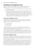
A fully meshed network topology is only recommended for a very small network. In the fully
meshed design, as shown in Figure 2.2, each router is connected to every other router in the net-
work. An advantage of this design is that it allows each site to communicate directly with each
other instead of going through a central site. However, scalability is severely limited.The number
of available ports and circuits must also be taken into consideration. Just like any fully meshed
topology, the amount of resources required to maintain a full mesh grows exponentially with the
number of devices.
Hub-and-Spoke Topology
A hub-and-spoke network topology is different from the fully meshed design, in that all traffic is
sent to a central site (or two) and then re-routed to the final destination. For example, in Figure
2.3, if a computer on Router1’s Ethernet network wanted to communicate with a computer on
www.syngress.com
Figure 2.1 Point-to-Point Topology
Ethernet
Router2
Ethernet
Router1
ISDN
Frame Relay
T-1
ATM
Figure 2.2 Fully Meshed Topology
ISDN
Frame Relay
T-1
ATM
Ethernet
Router2
Ethernet
Router3
Ethernet
Router1
253_BDCisco_02.qxd 10/13/03 5:40 PM Page 93
94 Chapter 2 • Wide Area Networking (WAN)
the Ethernet network for Router3, it must pass to the hub, Router2, which has a connection to
Router3.This type of design is more suitable for large-scale networks.
In order for this type of design to scale properly, the only site that needs to have significant
available resources is the hub. Contrary to the exponential growth in resources (circuits and ports)
required in a fully meshed design, the hub-and-spoke design only needs resources equal to the
number of sites. Another advantage of the hub-and-spoke design is that it is easy to configure and
troubleshoot.The complexity of the design is constrained to the hub router, as the spoke routers
will have relatively simple configurations. One key disadvantage to this design (but not to the
fully meshed topology) is that there is now a single point of failure in the network. If the hub
router goes down, none of the spoke sites are able to communicate with the rest of the network.
One popular solution to overcoming this potential failure issue is to design a dual-hub-and-
spoke network.This works well on large networks, retains the advantages of the hub-and-spoke
design, and overcomes the issue of a single point of failure by adding additional hubs to the con-
figuration. Should one hub fail, communications will continue through another hub.
High-Level Data Link Control
HDLC is Layer 2 data link protocol for encapsulation techniques on point-to- point dedicated
links. HDLC is derived from IBM’s Synchronous Data Link Control (SDLC) protocol suite.
HDLC specifies the encapsulation method in point-to-point synchronous links. It is the default
encapsulation for Cisco serial interfaces. Figure 2.4 provides a configuration for a simple point-
to-point network.
www.syngress.com
Figure 2.3 Hub-and-Spoke Topology
ISDN
Frame Relay
T-1
ATM
Ethernet
Router2
Hub
Ethernet
Router3
Spoke
Ethernet
Router1
Spoke
253_BDCisco_02.qxd 10/13/03 5:40 PM Page 94
Wide Area Networking (WAN) • Chapter 2 95
Data to be transmitted across a point-to-point link is encapsulated into HDLC frames. Cisco
HDLC, while it has an address field, typically does not use it since it is usually deployed in a
point-to-point configuration. Since HDLC is the default for Cisco serial interfaces, there is no
encapsulation hdlc command anywhere in the configuration in Figure 2.4.
HDLC simply concerns itself with transporting data from one router to another. It does not
offer much in the way of “extra” services such as authentication or compression. It is used for
synchronous communications, and with its low overhead (due to a limited set of capabilities), is
amongst the most efficient Layer 2 protocol that you can deploy for point-to-point networks.
PPP has its roots in HDLC.
Point to Point Protocol
PPP is designed for links that transport packets between two peers. PPP can operate across asyn-
chronous, synchronous; ISDN, and dial-up point-to- point implementations. PPP is an Open
Systems Interconnect (OSI) Layer 2 protocol standard that allows two devices to communicate
with each other using point-to-point connections such as an analog phone line, an ISDN line, or
a serial link.These point-to-point connections can be client-to-network or router-to-router.
PPP links provide a simultaneous, full-duplex, bi-directional operation, and are assumed to
deliver packets in order. PPP encapsulates higher layer protocol packets such as Internet Protocol
(IP), Internetwork Packet Exchange (IPX), and AppleTalk into PPP packets for transmission
across the link on a first-come, first-served basis.This encapsulation is accomplished by placing
www.syngress.com
Figure 2.4 Point-to-Point HDLC Configuration
Ethernet
Branch
Ethernet
Central
T-1
56K Circuit
Leased Line
hostname Central
!
interface Ethernet0
ip address 10.1.1.1 255.255.255.0
no shutdown
!
interface Serial0
ip address 192.168.3.1 255.255.255.0
no shutdown
!
router rip
network 192.168.3.0
network 10.0.0.0
hostname Branch
!
interface Ethernet0
ip address 192.168.1.1 255.255.255.0
no shutdown
!
interface Serial0
ip address 192.168.3.2 255.255.255.0
no shutdown
!
router rip
network 192.168.3.0
network 192.168.1.0
253_BDCisco_02.qxd 10/13/03 5:40 PM Page 95
96 Chapter 2 • Wide Area Networking (WAN)
the OSI Layer 3 network packet inside the PPP OSI Layer 2 frame and transmitting to the dis-
tant end where the PPP encapsulation frame is stripped away. The Layer 3 network packet is then
passed up to the next layer of the protocol stack. PPP is a standard international protocol, which
can be used in multi-vendor environments
PPP encapsulates network layer protocol information (including, but not limited to IP over
point-to-point links.This chapter looks at how this protocol works, and it also looks at the Link
Control Protocol (LCP) mechanisms for establishing, configuring, and testing the data-link con-
nection. PPP supports several authentication methods: the Password Authentication Protocol
(PAP), and the Challenge Handshake Authentication Protocol (CHAP).
To use PPP instead of HDLC, you would enter the following command in interface configu-
ration mode for each of the connected serial interfaces: central(config-if)# encapsulation
ppp. Keep in mind that the encapsulation must be the same on both sides of the link, or no
communication will be possible over that link.
There are four ways PPP can be used as a data link layer protocol on a Cisco router to pro-
vide access to computing resources:
■
Provides dial-in access to remote users.
■
Provides backup services over an asynchronous or synchronous connection in case a cir-
cuit fails between two routers.
■
Provides encapsulation between two routers over a leased line.
■
Provides dial-on-demand routing (DDR) services between two routers.
PPP Features
PPP offers several features that add the benefits of efficiency, security, and reliability to communi-
cations links.
■
Multiple Protocols per Communication Line PPP allows multiple network proto-
cols (such as IP, IPX, DECnet, Vines, or AppleTalk) to use the same communications
link. Each network protocol is transported by use of an additional associated Network
Control Protocol (NCP). For example, IP uses the IP Control Protocol (IPCP) and IPX
uses the Internet Packet Exchange Control Protocol (IPXCP) as their respective NCPs.
■
Authentication Security can be implemented over the link by the use of an authenti-
cation protocol such as PAP, Challenge-Handshake Authentication Protocol (CHAP), or
Microsoft’s MS-CHAP.These protocols are explained later in this chapter.
■
Link Configuration and Negotiation LCP manages link layer parameters (such as
the use of special escape characters and a maximum frame size) to add flexibility and
reliability to the communications link.
■
Error Detection Transmission errors can be detected through the use of Frame Check
Sequence (FCS) fields in the PPP frame.
■
Header Compression PPP allows for the compression of packet headers to more effi-
ciently utilize link bandwidth by reducing transmission overhead.
www.syngress.com
253_BDCisco_02.qxd 10/13/03 5:40 PM Page 96
Wide Area Networking (WAN) • Chapter 2 97
Bonding of Communications Links
PPP allows multiple communications links and/or remote access servers to be “bonded,” to
increase the amount of bandwidth between end devices.This bonding action allows two physical
communications lines to appear as a single virtual link for remote access services.The PPP frame
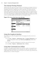
consists of the following six fields, as illustrated in Figure 2.5:
■
Flag (8 bits) start of frame consisting of the value 01111110
■
Address (8 bits) broadcast address consisting of the value 11111111
■
Control (8 bits) transmission control field consisting of the value 00000011
■
Protocol (8–16 bits) identifies network protocol encapsulated within frame
■
Data (Variable length) frame payload (maximum size is 1500 bytes)
■
FCS (8–16 bits) FCS for error detection. By prior agreement, consenting PPP applica-
tions can use 4 bytes for greater error detection
There are several components that make up the PPP. Each of these component sublayers exe-
cutes specific tasks that enable PPP to exhibit its many capabilities while remaining a stable and
robust Link layer protocol.
Link Control Protocol
LCP establishes and negotiates the data-link connection.The two most commonly set options are
the Maximum Receive Unit (MRU) and the setting that maps the character escape sequences—
the Asynchronous Control Character Map (ACCM).
Escape sequences are used to replace special control characters that may appear naturally in
the data stream, causing interruption of communication. An example is the XOFF character. Such
control characters are replaced with a two-character representation that is unlikely to appear
within the data stream.The use of escape sequences prevents the user data being sent from inad-
vertently interrupting the data flow by appearing as control signals to the computing devices or
the protocol in use.
LCP authenticates point-to-point peers by using either PAP or CHAP. Which authentication
protocol that LCP uses is configurable by the user. MS-CHAP is an authentication protocol pro-
prietary to Microsoft that is also supported by Cisco.These three authentication protocols are dis-
cussed later in this chapter.
LCP sits on top of the Physical layer and establishes, authenticates, and tests the functionality
of the data-link connection through a four phase process:
www.syngress.com
Figure 2.5 PPP Frame Format
0111110 1111111 00000011 00000011 00000011 00000011
FLAG ADDRESS CONTROL PROTOCOL DATA FCS
8 8 8 8-16 VARIABLE 8-16
SIZE IN BYTES
253_BDCisco_02.qxd 10/13/03 5:40 PM Page 97