the best damn cisco internetworking book period phần 6 pdf
Bạn đang xem bản rút gọn của tài liệu. Xem và tải ngay bản đầy đủ của tài liệu tại đây (900.23 KB, 117 trang )
IP Routing • Chapter 5 541
Link ID ADV Router Age Seq# Checksum
192.16.2.0 192.168.1.5 1581 0x80000185 0x2C08
192.16.3.0 192.168.1.5 1581 0x80000185 0x2112
debug Commands
debug should be used sparingly and specifically. Following are the debug commands that are spe-
cific to OSPF monitoring, taken directly from the Cisco IOS. Each command is self-explanatory.
We will mention that debug ip ospf adj is the best command for isolating and resolving the
cause of adjacency failures.
Router1# debug ip ospf ?
adj OSPF adjacency events
database-timer OSPF database timer
events OSPF events
flood OSPF flooding
hello OSPF hello events
lsa-generation OSPF lsa generation
packet OSPF packets
retransmission OSPF retransmission events
spf OSPF spf
tree OSPF database tree
Intermediate System to
Intermediate System (IS-IS)
IS-IS is the forgotten, overlooked link state routing protocol. Its better-known cousin, OSPF, has
all but eclipsed it. Further compounding the neglect of IS-IS is the fact that there are not as
many sources of information about it as there are about OSPF.
IS-IS is a link state routing protocol that is very similar to OSPF.This is no accident, as the
developers borrowed and improved on IS-IS when developing OSPF. IS-IS runs the Dijkstra
algorithm to build a complete picture of the routing domain (AS). Its backbone area (area 0) is
called the L2 area, while all other areas are classified as L1 areas. IS-IS routes by area within the AS
(L2 routing) and by the system ID within an area (L1 routing). That is, IS-IS uses the area address to
determine how to reach the area, and the system ID to reach a particular device once it gets to
the destination area.Therefore, it can be said that IS-IS routes on two levels: area and station.
There are two main flavors of IS-IS available: one for CLNS-only routing, and one for
routing both CLNS and IP.The latter is officially called Integrated IS-IS by Cisco. While IS-IS
was developed by the ISO to route CLNS, it has been modified to route IP. Its modular architec-
ture means that it can be further adapted to route other protocols such as IPX, should anyone
need or choose to develop that particular aspect of it.
www.syngress.com
253_BDCisco_05.qxd 10/15/03 10:24 AM Page 541
542 Chapter 5 • IP Routing
The “integrated” in Integrated IS-IS simply refers to the support that IS-IS has for non-
CLNS protocols such as IP. When you configure Integrated IS-IS, it is subject to the same princi-
ples and requirements that other IP routing protocols are (subnetting, masks, and so forth).
With IS-IS, even if you choose to route only IP, you still need to assign a CLNS address
(NET), as each IS communicates using CLNS, not IP.You need to enable CLNS, and assign NET,
to route IP. While Integrated IS-IS can and does route IP, it does so using its native tongue:
CLNS. It speaks CLNS to its peers, encapsulates routing updates in CLNS LSPs, and so on.
The first process that you enable on the IS automatically defaults to L1L2 configuration to
support any L2 interarea routing that might be required.This means that the IS will try to deter-
mine what the area it is attached to is. Subsequent processes automatically default to L1.
ISO Terminology
It is important to know the ISO terminology associated with IS-IS.
■
Intermediate System (IS) What the ISO calls a router.
■
End System (ES) The ISO elected to call hosts ESs. ESs do not route.
■
End System-Intermediate System Protocol (ES-IS) ES-IS is a discovery and reg-
istration protocol used by ESs to identify themselves to an IS, and to discover the IS in
their area. ES-IS is also used to register an ES with the IS, which builds a reachability
table of ES. ES-IS is not a routing protocol.
■
International Standard Organization Interior Gateway Routing Protocol
(ISO-IGRP) ISO-IGRP was Cisco’s first and only distance vector protocol for routing
CLNS. It does not route IP.
■
Link State Protocol data units (LSP) LSPs perform the same function for IS-IS
and ISO-IGRP that LSAs do for OSPF. Information about the networks in each area is
encapsulated within an LSP, and passed to neighboring routers.
■
Connectionless Network Protocol (CLNP) CLNP is the OSI equivalent of IP.
CLNP is a best-effort, unreliable, datagram protocol. It depends on higher layers to pro-
vide any needed reliability, including error detection and correction.
■
Connectionless Network Service (CLNS) CLNS is an amalgam of several OSI
protocols, including CLNP for addressing and datagram service, network service access
points (NSAP) for access points to higher layer protocols for various services, and so on.
It is analogous to TCP/IP, and the various layers in that stack.
■
Protocol Datagram Unit (PDU) PDU is the OSI term for the units of data that get
passed from one layer to the other.
■
Network Service Access Point (NSAP) NSAP is a logical point in the OSI suite
that identifies a particular network service. NSAP provides the addressing for a network
device, plus a special byte that identifies the particular service on a network device.
■
Network Entity Title (NET) This is the NSAP address for a particular network
device, ES or IS.The format, fields, and structure of the NET is the same as that of an
www.syngress.com
253_BDCisco_05.qxd 10/15/03 10:24 AM Page 542
IP Routing • Chapter 5 543
NSAP address; the only difference is that the NET SEL value is always 0. Contrast this
with a NSAP address with its SEL byte set to a nonzero value to identify a service on a
network device.
■
Level 1 (L1) Defining an area as L1 is the IS-IS equivalent of OSPF defining a
“normal” nonbackbone area. Areas that are not backbone areas (that is, do not provide
transit support to other areas) are classified as L1 areas.
■
Level 2 (L2) Backbone area that provides transit services to all other areas.
■
TLV A tuple in the CLNS PDU that enables a designer to add features, or support for
other network protocols.The best-known use of the TLV is to add routing support for
IP in IS-IS.The function that it performs is similar to the process of encapsulating one
network protocol’s traffic inside the packets and datagrams of another network protocol.
ISO Addressing and Topologies
An NSAP address can be likened to the combination of IP address and IP port numbers that
identify what protocols are being carried in the IP datagram. NSAP addresses are read from right
to left to determine the area, domain, and so forth.You do not assign NSAP addresses to an inter-
face; you assign them to the network device, and each interface is uniquely identified by data link
addresses such as the MAC address. On Cisco platforms, assign CLNS addresses to an IS by cre-
ating a network entity title (NET) (a NSAP address with its SEL set to 0). NSAP SEL uniquely
identifies a particular network service.
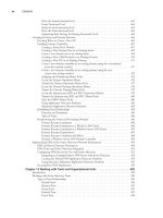
Figure 5.38 shows the NSAP address format.
■
Authority Format Identifier (AFI) One-byte field that defines the structure and
format of the rest of the NSAP address, including the length of the IDI field.
■
Initial Domain Identifier (IDI) Variable length. Identifies the domain that this par-
ticular address falls under.
■
Address Administration Variable length. Allows the NSAP address to be divided into
subaddresses, with authority for those addresses delegated. Commonly treated as part of
a domain.
www.syngress.com
Figure 5.38 NSAP Address Format
Size in Bytes Field
1
Authority Format Identifier (AFI)
Variable Initial Domain Identifier (IDI)
Variable
Address Administration
2
Area
6
Station (System ID)
1
Selector
Initial Domain Part
(IDP)
Domain Specific Part
(DSP)
253_BDCisco_05.qxd 10/15/03 10:24 AM Page 543
544 Chapter 5 • IP Routing
■
Area. Logical grouping of IS and ES L1 (intra-area traffic only), L2 (inter-area
traffic), or L1L2 (both types of traffic).
■
System ID CLNS address for the IS or ES. In many cases, it is a MAC address of a
particular interface used to identify a particular network device. It can be set manually.
■
Selector (SEL or NSEL) Identifies a particular network service, and is analogous to
the port number in an IP packet.The SEL value of 00 is reserved, and indicates a net-
work entity title (NET).
NSAP Address Format
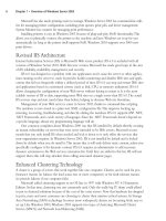
Figure 5.39 shows a NSAP address such as that commonly used by ISO-IGRP or IS-IS. If you
were simply given an NSAP address such as this, and read it like you would an IP address (left to
right), you would have problems.The reason for that is that the domain part of this address is
variable: it can be anywhere from one to ten bytes. So, how do you determine what part of a
NSAP address is your area, for example? As you can see in Figure 5.39, NSAP addresses are
written in hexadecimal format.
Starting at the right, the SEL field is always one byte.The six bytes to the left of that will
always be the system ID.The byte to the left of that is the area number. Anything left of the area
will be the domain and AFI.
IS-IS View of NSAP Address
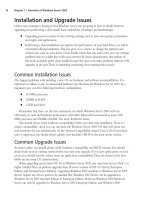
IS-IS has its own interpretation of the NSAP address as shown in Figure 5.40. Notice that there
is no domain, and that the two bytes that ISO-IGRP views as the area address are treated as High
Order-Domain Specific Part (HO-DSP). Up to the first 12 bytes of the NSAP address are treated
as the area address; the next six bytes are the system ID, and we conclude with the SEL byte set
to 0 identify a NET.
www.syngress.com
Figure 5.39 NSAP Address Illustrated
SELSystem IDAreaDomainAFI
49. aaaa.bbbb.cccc.dddd. 0000. 1122.3344.5566. 00
253_BDCisco_05.qxd 10/15/03 10:24 AM Page 544
IP Routing • Chapter 5 545
IS-IS routes by the area and the system ID; the lack of a domain indicates that IS-IS, like OSPF,
was not designed to route between ASs. Within an AS, IS-IS will use the area address to deliver data
to the correct area, and once in that area, use the system ID to deliver to the correct IS.
Using the NSAP address, 49.aaaa.bbbb.cccc.dddd.0000.1111.1111.1111.00, here is how IS-IS
interprets NSAP addresses. NSAP addresses are expressed in hexadecimal, with a minimum length
of 8 bytes, and a maximum length of 20 bytes.
Area: 49.aaaa.bbbb.cccc.dddd.0000
System ID: 1111.1111.1111
SEL: 00
Configuring CLNS-Only IS-IS
You create the IS-IS process using the router isis command. Next, assign it a NET (essentially
creating the areas and system ID) with the net command. Finally, put interfaces into the IS-IS
routing process using the clns router isis command.This command enables routing for CLNS
only; we will show you how to enable IP routing with IS-IS. Whenever you create an IS-IS
routing process, CLNS routing is automatically enabled.
Configuring Single Area IS-IS
Figure 5.41 shows a single area, CLNS-only IS-IS configuration.The area in this case is
49.dddd.eeee.ffff, and each IS has a unique system ID. Since they are in the same area, all routers
are doing L1 routing updates.
www.syngress.com
Figure 5.40 IS-IS Address Format
Size in Bytes
Fields
1
AFI
< 10
IDI
Variable
Area
6
System ID
1
NSEL (S)
ISO-IGRP Domain Address
ISO-IGRP System Address
ISO-IGRP Area Address
253_BDCisco_05.qxd 10/15/03 10:24 AM Page 545
546 Chapter 5 • IP Routing
The following configurations are for each router in Figure 5.41. Notice that the routing pro-
cess is configured, assigned a unique NET, and enabled on the appropriate interfaces.
Router1
clns routing
!
interface Serial0
no ip address
clns router isis area3
!
interface Serial1
no ip address
clns router isis area3
!
router isis area3
net 49.dddd.eeee.ffff.0003.1111.1111.1111.00
Router2
clns routing
!
interface Serial0
no ip address
clns router isis area3
!
interface Serial1
no ip address
clns router isis area3
www.syngress.com
Figure 5.41 Single Area CLNS-Only IS-IS
Area 49.dddd.eeee.ffff.0003
Router2Router1
Router4
Router3
System ID: 1111.1111.1111 System ID: 2222.2222.2222
System ID: 3333.3333.3333
System ID: 4444.4444.4444
253_BDCisco_05.qxd 10/15/03 10:24 AM Page 546
IP Routing • Chapter 5 547
!
router isis area3
net 49.dddd.eeee.ffff.0003.2222.2222.2222.00
Router3
clns routing
!
interface Serial0
no ip address
clns router isis area3
!
router isis area3
net 49.dddd.eeee.ffff.0003.3333.3333.3333.00
Router4
clns routing
!
interface Serial0
no ip address
clns router isis area3
!
router isis area3
net 49.dddd.eeee.ffff.0003.4444.4444.4444.00
Configuring Multi-area IS-IS.
The following demonstrates the necessary commands to configure multi-area IS-IS in Figure 5.42.
www.syngress.com
253_BDCisco_05.qxd 10/15/03 10:24 AM Page 547
548 Chapter 5 • IP Routing
When you are reading through the configurations that follow, notice how area
49.aaaa.bbbb.cccc.dddd.0001 is an L2 area, thanks to Router1, which passes L2 updates through
this area to all other routers, with the exception of Router2, which has all its links in the same
area, and functions as a L1 router.
Router1
clns routing
cns event-service server
!
interface Serial0
no ip address
clns router isis area00
!
interface Serial1
no ip address
clns router isis area00
!
interface Serial2
no ip address
clns router isis area00
!
www.syngress.com
Figure 5.42 CLNS-Only Multi-Area IS-IS
Area 49.aaaa.bbbb.cccc.dddd.0003
Area 49.aaaa.bbbb.cccc.dddd.0001
Area 49.aaaa.bbbb.cccc.dddd.0000
Router1
System ID: 1111.1111.1111
Router2
System ID: 2222.2222.2222
Router3
System ID: 3333.3333.3333
Area 49.aaaa.bbbb.cccc.dddd.0004
Router4
System ID: 4444.4444.4444
253_BDCisco_05.qxd 10/15/03 10:24 AM Page 548
IP Routing • Chapter 5 549
router isis area01
net 49.aaaa.bbbb.cccc.dddd.0001.1111.1111.1111.00
net 49.aaaa.bbbb.cccc.dddd.0000.1111.1111.1111.00
Router2
clns routing
!
interface Serial1
no ip address
clns router isis area00
!
router isis area00
net 49.aaaa.bbbb.cccc.dddd.0000.2222.2222.2222.00
net 49.aaaa.bbbb.cccc.dddd.0001.2222.2222.2222.00
Router3
clns routing
!
interface Loopback1
no ip address
clns router isis area03
!
interface Serial0
no ip address
clns router isis area01
!
router isis area00
net 49.aaaa.bbbb.cccc.dddd.0001.3333.3333.3333.00
!
router isis area03
net 49.aaaa.bbbb.cccc.dddd.0003.3333.3333.3333.00
is-type level-1
Router4
clns routing
!
interface Loopback1
no ip address
clns router isis area04
!
www.syngress.com
253_BDCisco_05.qxd 10/15/03 10:24 AM Page 549
550 Chapter 5 • IP Routing
interface Serial0
no ip address
clns router isis area04
!
router isis area04
net 49.aaaa.bbbb.cccc.dddd.0001.4444.4444.4444.00
net 49.aaaa.bbbb.cccc.dddd.0004.4444.4444.4444.00
Configuring Integrated IS-IS
We took you through the previous examples of configuring IS-IS for CLNS-only routing
because it is a building block to using Integrated IS-IS to route IP. We now turn our attention to
configuring Integrated IS-IS by turning on the IP routing features of IS-IS.The bulk of
Integrated IS-IS configuration is the same as CLNS-only IS-IS with the interface command ip
router isis enabled.This essentially makes IS-IS advertise that particular link (interface) to the
rest of the IS-IS speakers.
Assuming that you have already assigned IP addresses to your interfaces, the process of
enabling Integrated IS-IS then starts with router isis. While in IS-IS configuration mode, assign
a NET to the IS. Finally, enable the actual advertisement of IP via the interface command ip
router isis.
Single-Area Integrated IS-IS
Figure 5.43 shows the same single-area configuration we used in our CLNS-only IS-IS example.
Notice that except for the IP addresses on each interface, and the ip router isis command, the
configuration is almost the same. In our example, we have left the clns router isis command on
each interface; this command routes CLNS. It is not necessary to the routing of IP.
Router1
clns routing
www.syngress.com
Figure 5.43 Single-Area Integrated IS-IS
Area 49.dddd.eeee.ffff.0003
Router2
Router1
192.168.0.0/24
Router4
Router3
192.168.1.0/24
192.168.2.0/24
System ID: 1111.1111.1111 System ID: 2222.2222.2222
System ID: 3333.3333.3333
System ID: 4444.4444.4444
253_BDCisco_05.qxd 10/15/03 10:24 AM Page 550
IP Routing • Chapter 5 551
!
interface Serial0
ip address 192.168.1.1 255.255.255.0
ip router isis
clns router isis area3
!
interface Serial1
ip address 192.168.0.1 255.255.255.0
ip router isis
clns router isis area3
!
router isis area3
net 49.dddd.eeee.ffff.0003.1111.1111.1111.00
Router2
clns routing
!
interface Serial0
ip address 192.168.0.2 255.255.255.0
ip router isis
clns router isis area3
!
interface Serial1
ip address 192.168.2.2 255.255.255.0
ip router isis
clns router isis area3
!
router isis area3
net 49.dddd.eeee.ffff.0003.2222.2222.2222.00
Router3
clns routing
!
interface Serial0
ip address 192.168.1.2 255.255.255.0
ip router isis
clns router isis area3
!
router isis area3
net 49.dddd.eeee.ffff.0003.3333.3333.3333.00
www.syngress.com
253_BDCisco_05.qxd 10/15/03 10:24 AM Page 551
552 Chapter 5 • IP Routing
Router4
clns routing
!
interface Serial0
ip address 192.168.2.1 255.255.255.0
ip router isis
clns router isis area3
!
router isis area3
net 49.dddd.eeee.ffff.0003.4444.4444.4444.00
Multi-Area Integrated IS-IS
The process of configuring multi-area Integrated IS-IS follows the same steps as configuring
multi-area CLNS, only using IS-IS.The biggest differences are the addition of IP addresses and
the ip router isis command. Figure 5.44 and its configuration demonstrate this.
Router1
clns routing
!
interface Serial0
www.syngress.com
Figure 5.44 Multi-Area Integrated IS-IS
Area 49.aaaa.bbbb.cccc.dddd.0003
Area 49.aaaa.bbbb.cccc.dddd.0001
Area 49.aaaa.bbbb.cccc.dddd.0000
Router1
System ID: 1111.1111.1111
Router2
System ID: 2222.2222.2222
192.168.0.0/24
Router3
System ID: 3333.3333.3333
192.168.1.0/24
Area 49.aaaa.bbbb.cccc.dddd.0004
Router4
System ID: 4444.4444.4444
192.168.2.0/24
253_BDCisco_05.qxd 10/15/03 10:24 AM Page 552
IP Routing • Chapter 5 553
description Connection to Router3
ip address 192.168.1.1 255.255.255.0
ip router isis
clns router isis area00
!
interface Serial1
description Connection to Router2
ip address 192.168.0.1 255.255.255.0
ip router isis
clns router isis area00
!
interface Serial2
description Connection to Router4
ip address 192.168.2.1 255.255.255.0
ip router isis
clns router isis area00
!
router isis area00
net 01.aaaa.bbbb.cccc.dddd.0001.1111.1111.1111.00
net 02.aaaa.bbbb.cccc.dddd.0000.1111.1111.1111.00
net 03.aaaa.bbbb.cccc.dddd.
Router2
clns routing
cns event-service server
!
interface Serial1
description Connection to Router1
ip address 192.168.0.2 255.255.255.0
ip router isis
clns router isis area02
!
router isis area02
net 02.aaaa.bbbb.cccc.dddd.0000.2222.2222.2222.00
RouterC
clns routing
!
interface Loopback1
no ip address
www.syngress.com
253_BDCisco_05.qxd 10/15/03 10:24 AM Page 553
554 Chapter 5 • IP Routing
clns router isis area03
!
interface Serial0
ip address 192.168.1.2 255.255.255.0
ip router isis
clns router isis area00
!
router isis area00
net 02.aaaa.bbbb.cccc.dddd.0000.3333.3333.3333.00
net 03.aaaa.bbbb.cccc.dddd.0003.3333.3333.3333.00
!
router isis area03
net 03.aaaa.bbbb.cccc.dddd.0003.3333.3333.3333.00
is-type level-1
RouterD
clns routing
!
interface Loopback1
no ip address
clns router isis area04
!
interface Serial0
ip address 192.168.2.2 255.255.255.0
ip router isis
clns router isis area04
!
router isis area04
net 02.aaaa.bbbb.cccc.dddd.0000.4444.4444.4444.00
net 03.aaaa.bbbb.cccc.dddd.0004.4444.4444.4444.00
Monitoring IS-IS
Cisco provides many commands and facilities for monitoring and troubleshooting IS-IS. Several
of these commands and their output are shown in the following example. Some of these com-
mands are not necessarily specific to IS-IS; instead, they provide information about CLNS, but
knowing them can help verify and troubleshoot IS-IS.
Router3# show isis database ?
WORD LSPID in the form of xxxx.xxxx.xxxx.xx-xx or name.xx-xx
detail Detailed link state database information
l1 IS-IS Level-1 routing link state database
www.syngress.com
253_BDCisco_05.qxd 10/15/03 10:24 AM Page 554
IP Routing • Chapter 5 555
l2 IS-IS Level-2 routing link state database
level-1 IS-IS Level-1 routing link state database
level-2 IS-IS Level-2 routing link state database
verbose Verbose database information
| Output modifiers
You can view the details and contents of the IS-IS database as shown.
router3# show isis database
Area area00:
IS-IS Level-1 Link State Database:
LSPID LSP Seq Num LSP Checksum LSP Holdtime ATT/P/OL
routerA.00-00 0x00000008 0x0836 1096 1/0/0
2222.2222.2222.00-00 0x00000009 0x6362 557 0/0/0
routerC.00-00 * 0x00000005 0xE1BF 554 1/0/0
IS-IS Level-2 Link State Database:
LSPID LSP Seq Num LSP Checksum LSP Holdtime ATT/P/OL
routerA.00-00 0x00000002 0x0AF7 556 0/0/0
2222.2222.2222.00-00 0x00000007 0xCADD 557 0/0/0
routerC.00-00 * 0x00000003 0x31C1 560 0/0/0
Area area03:
IS-IS Level-1 Link State Database:
LSPID LSP Seq Num LSP Checksum LSP Holdtime ATT/P/OL
routerC.00-00 * 0x00000004 0x0175 560 1/0/0
Details of the IS-IS topology are available as well.
Router3# show isis topology
Area area00:
IS-IS paths to level-1 routers
System Id Metric Next-Hop Interface SNPA
routerA 20 2222.2222.2222 Se0 *HDLC*
2222.2222.2222 10 2222.2222.2222 Se0 *HDLC*
routerC
IS-IS paths to level-2 routers
System Id Metric Next-Hop Interface SNPA
routerA 20 2222.2222.2222 Se0 *HDLC*
2222.2222.2222 10 2222.2222.2222 Se0 *HDLC*
routerC
Area area03:
IS-IS paths to level-1 routers
System Id Metric Next-Hop Interface SNPA
www.syngress.com
253_BDCisco_05.qxd 10/15/03 10:24 AM Page 555
556 Chapter 5 • IP Routing
All the routing protocols discussed previously were designed to handle intra-AS routing.To
route effectively between different ASs requires a routing protocol such as BGP.
Border Gateway Protocol (BGP)
BGP is “the” exterior gateway protocol for routing between ASs, and between an AS and the
Internet. BGP is a path vector protocol, meaning that it routes AS by AS, rather than by hop or
by link. BGP updates are unicast to TCP port 179, meaning that it depends on TCP to recover
from network errors.
The current version is BGPv4, which is the focus of this section. Entire books have been
written about BGP, and some network engineers do nothing but BGP in their full-time career.
All of this is testament to the importance and complexity of BGP. Our intent in this section is to
provide with you an overview of BGP, and enough information that you can configure its funda-
mental features.
BGP can advertise classless routes that do not fall on a strict classful boundary.This support of
CIDR enables BGP to shrink routing tables and to consolidate multiple routes into a single
advertisement. Before we discuss the configuration of BGP on Cisco routers, we need to cover
several key BGP concepts and terms.
BGP Terminology
The following terms are bandied about when dealing with BGP.
■
Interior BGP (IBGP) BGP between routers in the same AS.The peering process and
exchange of routes are different from EBGP.
■
Exterior BGP (EBGP) BGP between routers in different ASs.
■
Prefix Consolidation of multiple routes into a single advertisement.
■
Peers Two BGP routers that have become neighbors for the purpose of exchanging
routing information.
Figure 5.45 illustrates IBGP and EBGP. Router1 and Router4 are in the same AS (65003), and
are IGBP peers. Router1, Router2, and Router3 are in different ASs, making them EBGP peers.
www.syngress.com
253_BDCisco_05.qxd 10/15/03 10:24 AM Page 556
IP Routing • Chapter 5 557
BGP Concepts
BGP operates by routers peering with each other over a TCP connection (port 179).This
peering is necessary to enable the routers to exchange BGP routes.The peering can be IBGP
(same AS) or EBGP (different AS), as previously discussed. Cisco routers running BGP can be in
only one AS, which is identified by its AS number (ASN), both public and private. Private ASN
can be used if a public ASN is not needed, or to do internal BGP routing.
EBGP peers must be directly connected. IBGP peers do not have to be directly connected,
but the router must have a route to its IBGP peer in its routing table via an IGP or static route.
EBGP can forego being directly connected in special circumstances, but must use a special mul-
tihop command provided by Cisco for such a configuration.
The propagation of information differs by the peering type. EBGP peers by default share all
information they receive from their peers, whereas IBGP peers will not advertise any IBGP
information to other IBGP peers, although they will share it with their EBGP peers.
Since BGP typically has a vast amount of routes to support, stability is its number-one goal.
Features such as route dampening that penalizes flapping routes are used to minimize updates
caused by network problems.
BGP will not advertise any prefix (supernetted or not) unless it has at least one route within
the routing table; that prefix can be learned via IBGP or EBGP, IGP, or other means, but it must
be present in the table to be advertised via BGP.This requirement is called synchronization,
which is enabled by default; Cisco provides a knob (no synchronization) to turn it off, meaning
that BGP will advertise regardless of whether it has the prefix in its table or not. BGP uses the
following tables to store its information.
www.syngress.com
Figure 5.45 Interior and Exterior BGP
AS65003
AS65001 AS65002
Router1
Router2
EBGP
Router3
EBGP
Router4
IBGP
253_BDCisco_05.qxd 10/15/03 10:24 AM Page 557
558 Chapter 5 • IP Routing
■
Neighbor table Used to host information on each neighbor (view with the show ip
bgp neighbor command).
■
BGP Routing table Contains routes learned by BGP, including suppressed routes to
the same destination deemed not to be the best. Such routes will replace the “best”
route should its next hop become unreachable. View with show ip bgp. It also stores
routes that were dampened for any reason.
■
IP Routing table Not a BGP-specific table, but does have the best route to a destina-
tion injected into it by BGP and other routing protocols.
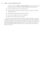
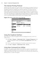
BGP uses a very strict process to choose the best route to add to the routing table as illus-
trated in Figure 5.46. BGP uses attributes (described in the figure) to make decisions at each
point between competing routes. One or more alternative routes to a destination will be stored
in the BGP routing table, while the best route will be used in the main routing table, as shown.
Configuring BGP
To enable BGP, you must identify the BGP process, and remember that the process is tied to your
ASN. If you are going to route traffic on the Internet or with other external ASs, you must use
www.syngress.com
Figure 5.46 BGP Route Selection Process
NEXT HOP
unreachable?
Highest Administrative
Weight?
Highest Local
Preference?
Originated by BGP
on local router?
Shortest AS_PATH?
Lowest Origin?
Lowest MED?
EBGP or IBGP
Path?
Nearest IGP
Neighbor?
Lowest BGP
Router ID?
Multiple routes to same network
If still more than one route…
If still more than one route…
If still more than one route…
If still more than one route…
If still more than one route…
If still more than one route…
If still more than one route…
If still more than one route…
Insert the route that passed all
criteria into the routing table.
If YES, discard.
If NO, discard.
If NO, discard.
If NO, discard.
If NO, discard.
If NO, discard.
If NO, discard.
If IBGP, discard.
If NO, discard.
If NO, discard.
253_BDCisco_05.qxd 10/15/03 10:24 AM Page 558
IP Routing • Chapter 5 559
an official ASN number assigned to you by ARIN (www.apnic.net/services/asn_guide.html).
Recall that BGP uses the ASN to route. If you are only using BGP internally (that is, will not be
peering with any AS outside your control), then you can use a private ASN in the range of
64512 through 65535. As with private IP addresses, you can use and assign these as you want.
Cisco routers can strip these numbers and use a public ASN should you later need to peer with
an external AS.
Bare Minimum BGP—EBGP
The bare minimum you need to enable BGP is to identify the process and at least one neighbor,
as shown here. Notice that we are using private ASN in our examples based on the network in
Figure 5.47.
NOTE
Only one AS per router translates to one BGP process per router.
Router1
router bgp 65001
neighbor 192.168.0.2 remote-as 64002
Router2
router bgp 64002
neighbor 192.168.0.1 remote-as 65535
network 192.168.2.0 mask 255.255.255.0
This establishes an EBGP peering between Router1 and Router2. Router1 will receive
192.168.2.0/16 from Router2, but will not route via BGP. It is not required that the common net-
work between two peers be advertised or participate in the BGP routing process, unlike most IGPs.
www.syngress.com
Figure 5.47 Minimum BGP
AS65002
192.168.2.0/24
AS65001
Router1
EBGP
192.168.0.0/24
Router2
.1
.2
253_BDCisco_05.qxd 10/15/03 10:24 AM Page 559
560 Chapter 5 • IP Routing
Bare Minimum BGP—IGBP
IBGP, as mentioned earlier, is the establishment of BGP peering relationships between routers in
the same AS. Recall that an IBGP peer will not share (advertise) any routes it learns via IBGP
with any of its IBGP peers. As a result, all IBGP peers must be fully meshed as shown in Figure
5.48, a requirement that can become unmanageable as the number of peers increases.
In Figure 5.48, there are four routers, and each has to have an IBGP peering statement to
three other routers in order for IBGP to be effective (indicated by the dashed lines), and to
ensure that all the routers have all the IBGP routes.The configuration for Figure 5.48 is provided
to illustrate the amount of effort required to execute this design. We turned on synchronization
here to decrease the time to get the route into the routing table. On Router1, we used the
neighbor command with its description keyword, which enables us to associate a descriptive
string of text to the neighbor.
Router1
interface Ethernet0
ip address 192.168.0.1 255.255.255.0
!
router bgp 65001
www.syngress.com
Figure 5.48 IBGP Peering
AS65001
Router1
Router2
IBGP
Router3
IBGP
Router4
IBGP
IBGP
IBGP
192.168.0.0/24
.1
.2
.4
.3
253_BDCisco_05.qxd 10/15/03 10:24 AM Page 560
IP Routing • Chapter 5 561
no synchronization
bgp log-neighbor-changes
network 192.168.1.0
neighbor 192.168.0.2 description Router2
neighbor 192.168.0.2 remote-as 65001
neighbor 192.168.0.3 description Router3
neighbor 192.168.0.3 remote-as 65001
neighbor 192.168.0.4 description Router4
neighbor 192.168.0.4 remote-as 65001
Router2
interface Ethernet0
ip address 192.168.0.2 255.255.255.0
!
router bgp 65001
no synchronization
bgp log-neighbor-changes
network 192.168.1.0
neighbor 192.168.0.1 remote-as 65001
neighbor 192.168.0.3 remote-as 65001
neighbor 192.168.0.4 remote-as 65001
Router3
interface Ethernet0
ip address 192.168.0.3 255.255.255.0
!
router bgp 65001
no synchronization
bgp log-neighbor-changes
network 192.168.1.0
neighbor 192.168.0.1 remote-as 65001
neighbor 192.168.0.2 remote-as 65001
neighbor 192.168.0.4 remote-as 65001
Router4
interface Ethernet0
ip address 192.168.0.4 255.255.255.0
!
router bgp 65001
no synchronization
bgp log-neighbor-changes
network 192.168.1.0
neighbor 192.168.0.1 remote-as 65001
www.syngress.com
253_BDCisco_05.qxd 10/15/03 10:24 AM Page 561
562 Chapter 5 • IP Routing
neighbor 192.168.0.2 remote-as 65001
neighbor 192.168.0.3 remote-as 65001
This is a fairly sizable configuration for a very small IBGP network. Imagine if this was a net-
work with even more routers…the configuration and management effort would be much greater.
Fortunately, Cisco offers several techniques for controlling IBGP peering, such as route reflectors
or confederations.
Route Reflectors
Route reflectors are a solution to reducing the number of IBGP peers needed to stabilize and syn-
chronize routing. Recall that IBGP peers do not advertise the routes of other IBGP peers by
default, yet all IBGP peers must have each other’s prefixes to maintain a consistent routing picture.
However, in a network of significant size, the number of IBGP peers can become unmanageable.
Route reflectors will pass the routing information that they receive from an IBGP peer, and
pass it (reflect it) to other IBGP peers in the AS. All IBGP peers will peer only with the route
reflect, rather than with every IBGP router in the AS. Only the route reflector needs to be con-
figured; all other routers (called router reflector clients, to use the lingo correctly) are configured
to peer with the route reflector.
Figure 5.49 shows the design and configuration of the previous example; only this time,
Router1 is a route reflector. Notice how much this has lessened our configuration requirements.
www.syngress.com
Figure 5.49 IBGP—Route Reflector
AS65001
Router1
Router2
IBGP
Router3
IBGP
Router4
IBGP
192.168.0.0/24
.1
.2
.4
.3
Route Reflector
253_BDCisco_05.qxd 10/15/03 10:24 AM Page 562
IP Routing • Chapter 5 563
Router1
interface Ethernet0
ip address 192.168.0.1 255.255.255.0
!
router bgp 65001
no synchronization
bgp log-neighbor-changes
network 192.168.1.0
neighbor 192.168.0.2 description Router2
neighbor 192.168.0.2 remote-as 65001
neighbor 192.168.0.2 route-reflector-client
neighbor 192.168.0.3 description Router3
neighbor 192.168.0.3 remote-as 65001
neighbor 192.168.0.3 route-reflector-client
neighbor 192.168.0.4 description Router4
neighbor 192.168.0.4 remote-as 65001
neighbor 192.168.0.4 route-reflector-client
Router2
interface Ethernet0
ip address 192.168.0.2 255.255.255.0
!
router bgp 65001
no synchronization
bgp log-neighbor-changes
network 192.168.1.0
neighbor 192.168.0.1 remote-as 65001
Router3
interface Ethernet0
ip address 192.168.0.3 255.255.255.0
!
router bgp 65001
no synchronization
bgp log-neighbor-changes
network 192.168.1.0
neighbor 192.168.0.1 remote-as 65001
Router4
interface Ethernet0
ip address 192.168.0.4 255.255.255.0
!
router bgp 65001
www.syngress.com
253_BDCisco_05.qxd 10/15/03 10:24 AM Page 563
564 Chapter 5 • IP Routing
no synchronization
bgp log-neighbor-changes
network 192.168.1.0
neighbor 192.168.0.1 remote-as 65001
As you can see, route reflectors “reflect” prefixes learned from one IBGP peer to another
IBGP peer. Notice how the number of IBGP peers has been reduced in this simple scenario. As
the configuration shows, route reflectors are enacted with the neighbor a.b.c.d route-
reflector-client for each client of the route reflector, and only on the route reflector.
BGP Confederations
Confederations are another technique to reduce the amount of IBGP peering by building an AS
within an AS.These confederations ASs are used to peer with other confederation ASs.This
essentially creates a holding AS used to interface with other ASs on behalf of the AS group.
Figure 5.50 shows AS65001 that has grouped Router1 and Router3 into confederation AS65011,
and Router2 and Router4 into AS65021.
Router1 (AS65011) and Router2 (AS65021) are EBGP peers on behalf of their confedera-
tion. Notice that where we previously had three IBGP peer statements per router, we now have a
total of two for the entire network, plus one EBGP peer relationship.The EBGP peers will share
whatever routing information they obtain with any IBGP peers they have.
www.syngress.com
Figure 5.50 BGP Confederation
AS65001
AS65021
AS65011
IBGP
EBGP
192.168.0.0/24
.1
.2
.4
.3
IBGP
Router2
Router4
Router1
Router3
253_BDCisco_05.qxd 10/15/03 10:24 AM Page 564
IP Routing • Chapter 5 565
The following creates the necessary configuration to support the BGP design in Figure 5.50.
Router1
interface Ethernet0
ip address 192.168.0.1 255.255.255.0
!
router bgp 65011
bgp log-neighbor-changes
bgp confederation identifier 65001
bgp confederation peers 65021
neighbor 192.168.0.3 remote-as 65011
neighbor 192.168.0.2 remote-as 65021
no auto-summary
Router2
interface Ethernet0
ip address 192.168.0.2 255.255.255.0
!
router bgp 65021
bgp log-neighbor-changes
bgp confederation identifier 65001
bgp confederation peers 65011
neighbor 192.168.0.1 remote-as 65011
neighbor 192.168.0.4 remote-as 65021
no auto-summary
Router3
interface Ethernet0
ip address 192.168.0.3 255.255.255.0
!
router bgp 65011
bgp log-neighbor-changes
bgp confederation identifier 65001
neighbor 192.168.0.1 remote-as 65011
no auto-summary
Router4
interface Ethernet0
ip address 192.168.0.4 255.255.255.0
!
router bgp 65021
bgp log-neighbor-changes
bgp confederation identifier 65001
neighbor 192.168.0.2 remote-as 65021
no auto-summary
www.syngress.com
253_BDCisco_05.qxd 10/15/03 10:24 AM Page 565