Fundamentals of Digital Electronics - Lab 8 potx
Bạn đang xem bản rút gọn của tài liệu. Xem và tải ngay bản đầy đủ của tài liệu tại đây (47.12 KB, 6 trang )
©
National Instruments Corporation 8-1 Fundamentals of Digital Electronics
Lab 8
Analog-to-Digital Converters,
Part I
The analog-to-digital converter, known as the A/D converter (read as A-to-D
converter) or the ADC, is the second key component to bridging the analog
and digital worlds. The ADC is the basis of digital voltmeters, digital
multimeters, multichannel analyzers, oscilloscopes, and many other
instruments. There are many different ADC designs, of which the ramp,
tracking, and successive approximation converters are common. This lab
looks at the ramp and tracking A/D converters.
Purpose of the Analog-to-Digital Converter
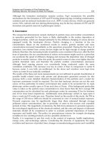
The purpose of an ADC converter is to produce a digital binary number that
is proportional to an analog input signal. The fundamental conversion
process is shown in the following diagram.
Figure 8-1.
Symbolic Design for an 8-Bit Analog-to-Digital Converter
A counter creates a test binary sequence, and its digital output is converted
into an analog voltage using a digital-to-analog converter. The DAC is a
basic element of many ADC circuits and was discussed in Lab 7. (This is a
good time to review its operation if you are not familiar with the DAC.) The
test voltage is then compared with the input signal. If the input signal is
larger than the test signal, the counter is increased to bring the test signal
closer to the input level. If the input signal is smaller than the test signal, the
counter is decreased to bring the test signal closer to the input level. The
Input Voltage
Test Voltage
+
–
C
b7 b0
Reset
Counter
DAC
Fundamentals of Digital Electronics 8-2
©
National Instruments Corporation
Lab 8 Analog-to-Digital Converters, Part I
process continues until the comparator changes sign, at which time the test
level will be within one count of the input level. Increasing the number of
bits of the counter and DAC increases the conversion resolution.
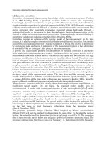
The Ramp ADC
The ramp ADC uses a binary counter and digital-to-analog converter to
generate a ramp test waveform. In this demonstration, an 8-bit binary up
counter, Binary Counter.vi, together with the 8-bit DAC, DAC.vi
(introduced in the last lab), generate the test waveform. The test level will
rise from 0 to 255 and repeat if left in the free running mode. However, when
the test level becomes greater than—or in this case, equal to—the input
level, the comparator will change sign and stop.
Figure 8-2.
LabVIEW VI to Simulate an 8-Bit Ramp ADC
The last value on the binary bits (b7-b0) is the digitized value of the input
voltage level. In the LabVIEW simulation, a wait time of 60 ms is chosen so
that the eye can follow the action. The comparator function is simulated with
the LabVIEW Equal function.
Load and run the simulation VI Ramp.vi and follow the action on the front
panel. Try other values of the input level and note that the conversion time
depends on the input voltage level.
Lab 8 Analog-to-Digital Converters, Part I
©
National Instruments Corporation 8-3 Fundamentals of Digital Electronics
Figure 8-3.
LabVIEW Front Panel of 8-Bit ADC Converter. The Comparator LED Indicator
Changes State When the Test Waveform Numeric Value Exceeds the Voltage Input
In the next simulation, Ramp4.vi, the binary counter is allowed to free run.
Whenever the test signal is greater than the input level, the comparator
changes sign. This intersection of the ramp waveform with the input level
can be seen on a chart display. The binary value of the counter at the
intersection point is the digitized signal. The transition of the comparator
indicates this event.
If the changing state of the comparator resets the binary counter, a true ramp
ADC is simulated. In this case, the binary counter is replaced with the binary
counter with reset, featured in Lab 6. Load the VI Ramp2.vi and observe
the action. Note that as soon as the test level reaches the input level, the
binary counter resets, and the ramp cycle starts all over again. In the display
below, the input level was changed three times.
Figure 8-4.
Chart Display of the Ramp ADC in Operation
An interesting feature, unique to the ramp ADC, is that the conversion time
depends on the magnitude of the input signal. Small input levels are
digitized faster than large input levels. The conversion time is thus
dependent on the input signal magnitude and the clock circuitry speed. For
an 8-bit DAC, variable conversion times may not be a problem when the
clock is running at megahertz frequencies, but for 12-bit DACs, this
property is a disadvantage.
Fundamentals of Digital Electronics 8-4
©
National Instruments Corporation
Lab 8 Analog-to-Digital Converters, Part I
The ramp ADC works equally well with a down counter that runs from
255-0. The change of state of the comparator again signals the binary count
that generates a test level equal to the input level.
LabVIEW Challenge
Design a ramp ADC that uses a down counter to generate the test waveform.
Could you use an up/down counter to track the input level?
Yes, such a conversion technique is called a tracking ADC, and it has the
fastest conversion time.
Tracking ADC
The first task for the tracking ADC is to use some technique such as a ramp
waveform to catch up to the input level. At that point, shown by the
intersection of the ramp waveform with the input level, the tracking
algorithm takes over.
Figure 8-5.
Tracking ADC Ramps Up to the Input Level Before Tracking Begins
The tracking algorithm is simply,
if
test level is greater than the signal level, decrease the count by one
else if
test level is less than the signal level, increase the count by one
and repeat forever.
In the following example, a positive ramp ADC technique is used to initially
catch up to the input level of 150.2. Once the input level is reached, the
tracking algorithm takes over.
Lab 8 Analog-to-Digital Converters, Part I
©
National Instruments Corporation 8-5 Fundamentals of Digital Electronics
By expanding the vertical scale, you can see the tracking algorithm in
action.
Figure 8-6.
Tracking ADC Output when Input is Constant
However, if the input level changes, the ADC must revert to a ramp
waveform to catch up to the input level. Provided the clock is fast enough,
the tracking can keep pace. But if the signal changes too quickly, the
digitized signal is lost until the test level catches up again. In practice, it is
the slewing speed of the DAC that limits the maximum input frequency that
the tracking ADC can follow.
Figure 8-7.
A Sudden Change in the Input Level Causes
the Test Level to Ramp Up to the New Level
Because the tracking ADC uses an up/down counter, the algorithm has the
same problem when the input signal suddenly falls below the test level. The
tracking ADC reverts to a down ramp (Figure 8-8) until the test level reaches
the input signal level.
Fundamentals of Digital Electronics 8-6
©
National Instruments Corporation
Lab 8 Analog-to-Digital Converters, Part I
Figure 8-8.
A Negative Change in the Input Level Causes
the Test Level to Ramp Down to the New Level
The VI called Tracking ADC.vi is used to demonstrate this technique and
to generate all the above charts. The algorithm shown on the block diagram
is quite simple. A LabVIEW Select function and the shift register on the
While Loop implements the algorithm.
Figure 8-9.
LabVIEW VI for the Tracking ADC
The Wait function is set to 0.10 second so that the user can observe the
action on the front panel. You can also use the Operating tool to redefine the
vertical axis scale to zoom in on the action as the simulation is in progress.
To observe the tracker catching up to a varying input, reduce the input
constant for the Wait function in Figure 8-9 to 1 ms.
Lab 8 Library VIs (Listed in the Order Presented)
• Ramp.vi (8-bit ramp ADC, conversion slowed for easy viewing)
• Ramp4.vi (ramp ADC with no feedback from comparator)
• Ramp2.vi (8-bit ramp ADC with chart output)
• Tracking ADC1.vi
• Binary Counter.vi (subVI 8-bit binary counter)
• BIN_RST.vi (subVI 8-bit binary counter with external reset)
• DAC.vi (subVI 8-bit DAC)
• FlipFlop.vi (subVI)