SolidWorks Tutorial - Part 3 pptx
Bạn đang xem bản rút gọn của tài liệu. Xem và tải ngay bản đầy đủ của tài liệu tại đây (1.39 MB, 37 trang )
SolidWorks
®
Tutorial 3
MAGNETIC BLOCK
Preparatory Vocational Training
and Advanced Vocational Training
To be used with SolidWorks
®
Educational Release 2008-2009
SolidWorks voor VMBO en MBO
Tutorial 3: magnetic Block
2
© 1995-2009, Dassault Systèmes SolidWorks Corp.
300 Baker Avenue
Concord, Massachusetts 01742 USA
All Rights Reserved
U.S. Patents 5,815,154; 6,219,049; 6,219,055
Dassault Systèmes SolidWorks Corp. is a Dassault Systèmes
S.A. (Nasdaq:DASTY) company.
The information and the software discussed in this document
are subject to change without notice and should not be consi-
dered commitments by Dassault Systèmes SolidWorks Corp.
No material may be reproduced or transmitted in any form or
by any means, electronic or mechanical, for any purpose
without the express written permission of Dassault Systèmes
SolidWorks Corp.
The software discussed in this document is furnished under a
license and may be used or copied only in accordance with
the terms of this license. All warranties given by Dassault
Systèmes SolidWorks Corp. as to the software and documen-
tation are set forth in the Dassault Systèmes SolidWorks
Corp. License and Subscription Service Agreement, and
nothing stated in, or implied by, this document or its contents
shall be considered or deemed a modification or amendment
of such warranties.
SolidWorks® is a registered trademark of Dassault Systèmes
SolidWorks Corp.
SolidWorks 2009 is a product name of Dassault Systèmes So-
lidWorks Corp.
FeatureManager® is a jointly owned registered trademark of
Dassault Systèmes SolidWorks Corp.
Feature Palette™ and PhotoWorks™ are trademarks of Das-
sault Systèmes SolidWorks Corp.
ACIS® is a registered trademark of Spatial Corporation.
FeatureWorks® is a registered trademark of Geometric Soft-
ware Solutions Co. Limited.
GLOBEtrotter® and FLEXlm® are registered trademarks of
Globetrotter Software, Inc.
Other brand or product names are trademarks or registered
trademarks of their respective holders.
COMMERCIAL COMPUTER
SOFTWARE - PROPRIETARY
U.S. Government Restricted Rights. Use, duplication, or dis-
closure by the government is subject to restrictions as set
forth in FAR 52.227-19 (Commercial Computer Software -
Restricted Rights), DFARS 227.7202 (Commercial Comput-
er Software and Commercial Computer Software Documen-
tation), and in the license agreement, as applicable.
Contractor/Manufacturer:
Dassault Systèmes SolidWorks Corp., 300 Baker Avenue,
Concord, Massachusetts 01742 USA
Portions of this software are copyrighted by and are the
property of Electronic Data Systems Corporation or its sub-
sidiaries, copyright© 2009
Portions of this software © 1999, 2002-2009 ComponentOne
Portions of this software © 1990-2009 D-Cubed Limited.
Portions of this product are distributed under license from
DC Micro Development, Copyright © 1994-2009 DC Micro
Development, Inc. All Rights Reserved.
Portions © eHelp Corporation. All Rights Reserved.
Portions of this software © 1998-2009 Geometric Software
Solutions Co. Limited.
Portions of this software © 1986-2009 mental images GmbH
& Co. KG
Portions of this software © 1996-2009 Microsoft Corpora-
tion. All Rights Reserved.
Portions of this software © 2009, SIMULOG.
Portions of this software © 1995-2009 Spatial Corporation.
Portions of this software © 2009, Structural Research &
Analysis Corp.
Portions of this software © 1997-2009 Tech Soft America.
Portions of this software © 1999-2009 Viewpoint Corpora-
tion.
Portions of this software © 1994-2009, Visual Kinematics,
Inc.
All Rights Reserved.
SolidWorks Benelux developed this tutorial for self-training with the SolidWorks 3D CAD program. Any other use
of this tutorial or parts of it is prohibited. For questions, please contact SolidWorks Benelux. Contact informa-
tion is printed on the last page of this tutorial.
Initiative: Kees Kloosterboer (SolidWorks Benelux)
Educational Advisor: Jack van den Broek (Vakcollege Dr. Knippenberg)
Realization: Arnoud Breedveld (PAZ Computerworks)
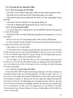
Magnetic Block
In this exercise you will make a magnetic block. To do so, you will create a few parts, which you will as-
semble. You will learn the following new applications in this tutorial:
x You will make two configurations of a part.
x You will weld the parts together.
x You will make holes using the Hole Wizard.
x You will use standardized parts from the Parts Library.
x You will assign different colors to different parts.
Work plan To make this assembly, you will have to make several parts. We will start
with a simple rectangular base with a thickness of 20mm per the drawing
below.
We will perform the following steps:
1. Take a piece of material of 150x300x20.
2. Round off the four corners with a radius of 10 mm.
3. Drill four holes of Ø17.
SolidWorks voor VMBO en MBO
Tutorial 3: magnetic Block
3
1 Start SolidWorks and open
a new part.
2 Click on ‘Top Plane’ in the
FeatureManager (the left
column of your screen in
which all the parts of your
model are listed).
In this plane we will be
making a sketch.
3 Click on ‘Sketch’ in the
CommandManager to re-
veal the correct buttons
and next on Rectangle to
draw a rectangle.
4 1. Click on Center Rec-
tangle in the Com-
mandManager.
2. Click on the origin.
3. Click at a random point
as in the view at the
right (#3) to draw a
rectangle.
5 Next use the command
Smart Dimension to deter-
mine two dimensions at
the sides of the rectangle:
150x300.
You have used Smart Di-
mension before. Can you
remember this? If not, look
it up again in Tutorial 2,
steps 7 to 10.
SolidWorks voor VMBO en MBO
Tutorial 3: magnetic Block
4
6 1. Click on ‘Features’ in
the CommandManager.
2. Click on ‘Extruded
Boss/Base’.
7 1 Set the thickness at
20mm.
2 Click on OK.
8 Next, we will round off the
corners.
Click on ‘Fillet’ in the
CommandManager.
The ‘Fillet’ command looks
similar to the ‘Chamfer’
command that we used
previously.
SolidWorks voor VMBO en MBO
Tutorial 3: magnetic Block
5
9 1. Make sure the option
‘Full preview’ is se-
lected.
2-5 Next select the four
edges you want to
round off.
6. Set the radius at
10mm.
7. Click on OK.
10 Next, select the top plane
of the model just by click-
ing it.
11 Click on ‘Sketch’ and next
on Rectangle to draw a
rectangle.
SolidWorks voor VMBO en MBO
Tutorial 3: magnetic Block
6
12 Click on the Standard
Views button at the top of
the screen and next on
Normal To.
The model now rotates it-
self to provide a straight-
on view of the plane on
which we are making the
sketch.
It does not matter if the
model is positioned hori-
zontally or vertically on
your screen.
13 4. Click on Center Rec-
tangle in the Property-
Manager.
5. Click on the origin.
6. Click at a random point
like in the view at the
right (#3) to draw a
rectangle.
14 Next, add two more di-
mensions with the com-
mand Smart Dimension:
the horizontal dimension of
240 and the vertical di-
mension of 100.
15 Next click on ‘Exit Sketch’
in the CommandManager.
The sketch remains visible,
but turns grey.
Notice that we will make a
sketch, but do NOT make a
feature of it. Later, you will
see how we will use sketch
like this.
SolidWorks voor VMBO en MBO
Tutorial 3: magnetic Block
7
16 First, click on ‘Features’ in
the CommandManager and
next on ‘Hole Wizard’.
17 You will have to set the
features of the holes in the
PropertyManager.
1 Choose a ‘Hole Type’:
choose Hole.
2 Check that the ‘Stan-
dard’ is set at ‘ISO’.
3 Check that the ‘Type’ is
set at ‘Drill sizes’.
4 Set the diameter at
Ø17mm.
5 Set the ‘End Condition’
at ‘Through All’.
6 Click on the tab page
‘Positions’.
18 Next, click on the four cor-
ners of the rectangle you
have drawn before and
then click OK.
SolidWorks voor VMBO en MBO
Tutorial 3: magnetic Block
8
Tip!
The first part is ready now.
We could also have created the holes we just made with the Extruded Cut
feature. However, the Hole Wizard we just used is often very convenient,
even more so if the holes you want to make area bit more complicated.
Later on, we will see an example of this.
Work plan The second part we need looks very much like the last one. Instead of the
normal holes we now need tapped holes. You could create a whole new
part, but it is much easier to make a second version within this part. We
call this a Configuration.
We will do following:
1. Create a new configuration.
2. Remove the normal holes in the new configuration.
3. Make tapped holes instead.
If you experience any problems in working with configurations, you can al-
ways create a new part in exactly the same way as the first part. Use step
27 instead of step 17.
SolidWorks voor VMBO en MBO
Tutorial 3: magnetic Block
9
19 Click on the third tab in the
FeatureManager. Instead
of the FeatureManager or
the PropertyManager, the
ConfigurationManager now
appears.
20 There is only one configu-
ration, named ‘Default
[Part1]’. Click slowly on the
name once or twice to
change the name.
21 Rename this item as:
‘Holes’. Push the <Enter>
key on your keyboard.
22 Next, make a new configu-
ration:
1 Right-click on the top
line of the list (‘Part1
Configuration(s)’)
2 Select ‘Add Configura-
tion’ in the menu.
23 Fill in the name of this con-
figuration in the Property-
Manager as ‘Taps’, and
then click OK.
SolidWorks voor VMBO en MBO
Tutorial 3: magnetic Block
10
24 Click on the first tab of the
ConfigurationManager to
go to the FeatureManager.
Tip! At this point we have two configurations but only one is active: the one we
are working in.
x In the ConfigurationManager you can recognize the active configuration
because it is printed in black (check this at step 24).
x In the FeatureManager the name of the active configuration is at the
top of the list, behind the name of the created part (check this at step
25).
25 Click on the last feature
you created (the holes).
Click on Suppress in the
menu.
The holes now disappear
from the model and are
printed grey in the Featu-
reManager.
Tip! Instead of clicking on a feature with your left mouse button, you can also
use the right mouse button. You will see a much more extended menu.
26 Click on ‘Hole Wizard’ in
the CommandManager.
SolidWorks voor VMBO en MBO
Tutorial 3: magnetic Block
11
27 Set the properties of the
holes in the PropertyMa-
nager.
1 Choose ‘Hole Type’:
Tap.
2 Check that the ‘Stan-
dard’ is set at ‘ISO’.
3 Check that the ‘Type’ is
set at ‘Tapped hole’.
4 Set the dimension at
M16.
5 Set the ‘End Condition’
at ‘Through All’.
6 Click on the tab ‘Posi-
tions’.
28 Click on the four corners of
the rectangle to position
the holes and then click on
OK.
29 Now click on the sketch
that you have used to posi-
tion the holes. Usually it is
named ‘Sketch2’ or
‘Sketch3’. The number can
vary.
Click on Hide in the menu
that appears.
SolidWorks voor VMBO en MBO
Tutorial 3: magnetic Block
12
30 Save the file as
slab.SLDPRT.
31 Next click on the third tab
at the top of the Feature-
Manager to go to the Con-
figurationManager.
32 There are now two ver-
sions (configurations) of
the base model: one with
normal holes and one with
tapped holes.
Only one of these two is
active (and visible).
By double-clicking on a
configuration in the Confi-
gurationManager you will
make the configuration ac-
tive. Try this now.
33 Close the file by clicking on
File and next on Close.
It is not necessary to save
the file again when the
program asks for it.
Tip! In this product we need two plates of material. These are the same of
course, only the hole properties are different from each other. Of course
we could have created a second plate, but then we had to do a certain
number of commands a second time. This was not necessary because we
used configurations.
So, in a case like this, it is a good idea to work with the configurations
command. Within a single part you create different ‘versions’ of the same
product or part. In the ConfigurationManager you can choose which version
is active: this is the version you work with to change the features.
SolidWorks voor VMBO en MBO
Tutorial 3: magnetic Block
13
Within every version you can make features invisible (suppressed) or visible
(unsuppressed). By doing so, we create more than one version, and in
every version you have different features visible, like the normal holes or
the tapped holes in the two versions we have just completed.
Of course there are also many features which have to be visible in every
version, like in the first part you have created. By changing a dimension in
one version, the other versions will be changed automatically!
Work plan The next part we have to create is the bracket on top for the crane hook.
To create this part, we only have to make a sketch and extrude it.
34 Open a new part, select
the ‘Front Plane’ and create
a sketch.
35 Click on ‘Sketch’ in the
CommandManager next on
‘Centerline’.
SolidWorks voor VMBO en MBO
Tutorial 3: magnetic Block
14
36 Draw a centerline from the
origin straight up.
37 Next, draw a circle. Click
on the top end of the cen-
terline. Move the mouse
and click again to create a
circle with a random ra-
dius.
38 Next, draw two lines:
1 Click on Line in the
CommandManager.
2 Click on the origin.
3 Move the mouse hori-
zontally to the left and
click again to set a
second point (check the
view on the right).
4 Move the mouse to-
wards the circle. Move
the mouse
over
the cir-
cle until the two yellows
icons appear as in the
illustration on the right.
When this is the case,
you click to create a line
which is in contact with
the circle.
SolidWorks voor VMBO en MBO
Tutorial 3: magnetic Block
15
39 Next, we will copy two
lines.
Push the <Esc> key on
your keyboard to end the
line command.
1. Select the first line.
2. Hold the <Ctrl> key
and select a second
line.
3. Keep the <Ctrl> key
down and select the
centerline.
4. Click on ‘Mirror Entities’
in the CommandMa-
nager.
40 The bottom part of the cir-
cle has to be removed.
1 Click on ‘Trim Entities’
in the CommandMa-
nager.
2 Select the option ‘Trim
to closest’ in the Pro-
pertyManager.
3,4 Next, click on the two
parts of the circle
which have to be re-
moved.
41 Add three dimensions to
the sketch using Smart
Dimension. Check the illu-
stration on the right.
SolidWorks voor VMBO en MBO
Tutorial 3: magnetic Block
16
42 Finally, draw another circle
to make a hole with a di-
mension of Ø24.
43 We can extrude the ma-
terial of the sketch now.
1 Click on ‘Features’ in
the CommandManager.
2 Click on ‘Extruded
Boss/Base’.
44 1 Select the option ‘Mid
Plane’ at Direction1 in
the PropertyManager.
2 Set the thickness at
20mm.
3 Click on OK.
SolidWorks voor VMBO en MBO
Tutorial 3: magnetic Block
17
45 Save the file as
crane_hook.SLDPRT.
46 The parts are ready for the
assembly.
1 Click on New in the
toolbar.
2 Select file type ‘Assem-
bly’.
3 Click on OK.
47 We have closed the file
slab.SLDPRT. For this rea-
son it is not in the list in
the PropertyManager.
Click on ‘Browse…’
Pay attention! Even when
the file is not closed and is
in the list, click on
‘Browse…’. If you do not
do this, you will not be
able to select the right con-
figuration.
SolidWorks voor VMBO en MBO
Tutorial 3: magnetic Block
18
Tip! Normally, the Insert Components command starts automatically when a
new assembly is opened. If this does not happen, click on ‘Insert Compo-
nents’ in the CommandManager.
48 Find the file ‘slab.SLDPRT’,
which we made earlier.
1 Select the file.
2 This file contains more
than one configuration
so you have to choose
which configurations
you will be using. Select
‘Holes’.
3 Click on ‘Open’.
49 Now the part is fixed to the
cursor. Do
not
click in the
graphical area, but click on
OK in the PropertyManag-
er.
50 To add the next part, click
on ‘Insert Components’ in
the CommandManager.
SolidWorks voor VMBO en MBO
Tutorial 3: magnetic Block
19
51 1 Select the file
‘Crane_hook’ in the
list,
2 Place the part at a
random position in the
assembly.
Tip! Did you execute the previous steps correctly? You will notice that the base
part cannot be moved, while the crane hook can be moved around. This is
because the first part you chose is Fixed. In the FeatureManager you can
verify this because in front of the filename Slab is an ‘(f)’, and before the
Crane_hook a ‘(-)’. The part with an (f) is a floating part and can be
moved around.
Be sure at all times that ONE part is Fixed; the other parts can be con-
nected to this with the mate command.
You can make any part Fixed or Floating by clicking on it with the right
mouse buttons and choosing Fix or Float.
52 Click on ‘Mate’ in the
CommandManager.
SolidWorks voor VMBO en MBO
Tutorial 3: magnetic Block
20
53 Click on the upper surface
of the part.
54 Rotate the model so you
get a clear view of the bot-
tom side of the crane
hook. Push the scroll-wheel
and move your mouse to
rotate.
1 Click on the bottom of
the crane hook.
The parts now move to-
ward each other.
2 Click on OK.
55 The selection field in the
PropertyManager is now
empty, and you can start
with the next mate imme-
diately.
To center the crane hook,
we use the standard planes
Front Plane and Right
Plane. You cannot select
them in the model, howev-
er, only in the FeatureMa-
nager.
Because the PropertyMa-
nager is now visible and
not the FeatureManager,
you must use the Feature-
Manager in the graphical
area.
Click on the ‘+’ directly in
front of the file name.
SolidWorks voor VMBO en MBO
Tutorial 3: magnetic Block
21
56 Next, click on the ‘+’ in
front of both parts. Pay at-
tention: after clicking on
the first ‘+’ the list ex-
pands.
57 1 Next, select the ‘Front
Plane’ within the part
‘Slab’
2 Also select the ‘Front
Plane’ within the part
‘Crane_hook’.
3 Next, click on OK.
SolidWorks voor VMBO en MBO
Tutorial 3: magnetic Block
22
58 1 Select the ‘Right Plane’
within the part ‘Slab’.
2 Also select the ‘Right
Plane’ within the part
‘Crane_hook’.
3 Click on OK.
4 Click on OK again to
confirm the mate, and
again to close down
the mate command.
59 Save the assembly as:
crane_hook-
complete.SLDASM.
60 We are going to weld the
parts together.
1 Click on the arrow be-
low the ‘Assembly Fea-
tures’ in the Com-
mandManager.
2 Click on the ‘Weld Sym-
bol’.
SolidWorks voor VMBO en MBO
Tutorial 3: magnetic Block
23
61 Select the ‘Fillet’ type in
the menu that appears.
This is a corner weld and
the most simple to add.
Then, click on ‘Next’.
62 We will make a curved
weld. Set the features as in
the illustration on the right,
and click on ‘Next’.
SolidWorks voor VMBO en MBO
Tutorial 3: magnetic Block
24
63 Next, select the plane you
want to weld: the upper
plane of the base and the
vertical plane of the crane
hook.
Click on ‘Next’.
64 The weld will be a separate
part in the assembly, and
so it will be saved as a
separate file. This time, So-
lidWorks determines the
name of this ‘part’.
Click on ‘Finish’.
65 The weld is now made. So-
lidWorks automatically
adds a weld symbol.
Drag the symbol to a posi-
tion beside the model.
If you want to change the
symbol, double-click on it.
In one of the tutorials that
follow we will get back to
this.
SolidWorks voor VMBO en MBO
Tutorial 3: magnetic Block
25