SolidWorks Tutorial - Part 5 pdf
Bạn đang xem bản rút gọn của tài liệu. Xem và tải ngay bản đầy đủ của tài liệu tại đây (1.19 MB, 34 trang )
SolidWorks
®
Tutorial 5
TIC-TAC-TOE
Preparatory Vocational Training
and Advanced Vocational Training
To be used with SolidWorks
®
Educational Release 2008-2009
SolidWorks for VMBO en MBO
Tutorial 5: Tic Tac Toe
2
© 1995-2009, Dassault Systèmes SolidWorks Corp.
300 Baker Avenue
Concord, Massachusetts 01742 USA
All Rights Reserved
U.S. Patents 5,815,154; 6,219,049; 6,219,055
Dassault Systèmes SolidWorks Corp. is a Dassault Systèmes
S.A. (Nasdaq:DASTY) company.
The information and the software discussed in this document
are subject to change without notice and should not be consi-
dered commitments by Dassault Systèmes SolidWorks Corp.
No material may be reproduced or transmitted in any form or
by any means, electronic or mechanical, for any purpose
without the express written permission of Dassault Systèmes
SolidWorks Corp.
The software discussed in this document is furnished under a
license and may be used or copied only in accordance with
the terms of this license. All warranties given by Dassault
Systèmes SolidWorks Corp. as to the software and documen-
tation are set forth in the Dassault Systèmes SolidWorks
Corp. License and Subscription Service Agreement, and
nothing stated in, or implied by, this document or its contents
shall be considered or deemed a modification or amendment
of such warranties.
SolidWorks® is a registered trademark of Dassault Systèmes
SolidWorks Corp.
SolidWorks 2009 is a product name of SolidWorks Corpora-
tion.
FeatureManager® is a jointly owned registered trademark of
Dassault Systèmes SolidWorks Corp.
Feature Palette™ and PhotoWorks™ are trademarks of Das-
sault Systèmes SolidWorks Corp.
ACIS® is a registered trademark of Spatial Corporation.
FeatureWorks® is a registered trademark of Geometric Soft-
ware Solutions Co. Limited.
GLOBEtrotter® and FLEXlm® are registered trademarks of
Globetrotter Software, Inc.
Other brand or product names are trademarks or registered
trademarks of their respective holders.
COMMERCIAL COMPUTER
SOFTWARE - PROPRIETARY
U.S. Government Restricted Rights. Use, duplication, or dis-
closure by the government is subject to restrictions as set
forth in FAR 52.227-19 (Commercial Computer Software -
Restricted Rights), DFARS 227.7202 (Commercial Comput-
er Software and Commercial Computer Software Documen-
tation), and in the license agreement, as applicable.
Contractor/Manufacturer:
Dassault Systèmes SolidWorks Corp., 300 Baker Avenue,
Concord, Massachusetts 01742 USA
Portions of this software are copyrighted by and are the
property of Electronic Data Systems Corporation or its sub-
sidiaries, copyright© 2009
Portions of this software © 1999, 2002-2009 ComponentOne
Portions of this software © 1990-2009 D-Cubed Limited.
Portions of this product are distributed under license from
DC Micro Development, Copyright © 1994-2009 DC Micro
Development, Inc. All rights reserved.
Portions © eHelp Corporation. All Rights Reserved.
Portions of this software © 1998-2009 Geometric Software
Solutions Co. Limited.
Portions of this software © 1986-2009 mental images GmbH
& Co. KG
Portions of this software © 1996-2009 Microsoft Corpora-
tion. All Rights Reserved.
Portions of this software © 2009, SIMULOG.
Portions of this software © 1995-2009 Spatial Corporation.
Portions of this software © 2009, Structural Research &
Analysis Corp.
Portions of this software © 1997-2009 Tech Soft America.
Portions of this software © 1999-2009 Viewpoint Corpora-
tion.
Portions of this software © 1994-2009, Visual Kinematics,
Inc.
All Rights Reserved.
SolidWorks Benelux developed this tutorial for self-training with the SolidWorks 3D CAD program. Any other use
of this tutorial or parts of it is prohibited. For questions, please contact SolidWorks Benelux. Contact informa-
tion is printed on the last page of this tutorial.
Initiative: Kees Kloosterboer (SolidWorks Benelux)
Educational Advisor: Jack van den Broek (Vakcollege Dr. Knippenberg)
Realization: Arnoud Breedveld (PAZ Computerworks)
TIC-TAC-TOE
In this tutorial we will create a Tic-Tac-Toe game. The game consists of two plates that are on top of
each other. In the top plate, there are holes for inserting small cylinders marked ‘X’ or ‘O’. In this exercise
we repeat a lot of tools we already know and add a few others: working with configurations and the use
of standard Parts. Some new features in this tutorial include working with tolerances and fittings and
working with patterns.
Work plan First, we will create the top plate. We will do this according to the drawing
below.
We will execute following steps:
1. First, we will create the top plate first with dimensions 60 x 60 x
10.
2. Then, we will make four counter bore holes.
3. Finally, we will create a pattern of 9 holes.
SolidWorks for VMBO en MBO
Tutorial 5: Tic Tac Toe
3
1 Start SolidWorks and open
a new part.
2 1. Select the ‘Top Plane’.
2. Click on ‘Sketch’ in the
CommandManager.
3. Click on Rectangle.
3 Draw a rectangle:
1. Click on Center Rec-
tangle in the Property-
Manager.
2. Click on the origin.
3. Click at a random point
to get the second cor-
ner.
SolidWorks for VMBO en MBO
Tutorial 5: Tic Tac Toe
4
4 Add a horizontal dimension
to the sketch, as in the illu-
stration on the right.
Change this dimension to
60mm.
Push the <Esc> key on the
keyboard to end the com-
mand.
5 Set the length of the hori-
zontal and vertical lines to
the same length:
1. Select a vertical line.
2. Push the <Ctrl> button
and click on a horizon-
tal line.
3. Click on ‘Equal’ in the
PropertyManager.
Tip! Remember that a blue field in the PropertyManager is a selection field. You
can add elements by clicking on them in your model and you can also de-
lete elements from it (e.g., when you have selected a wrong element).
When you see a pink-colored selection field, you do not have to use the
Ctrl> key to select more than one element.
To remove an element from the list, click on the element in the pink field
and push the <Del> (delete) key on your keyboard. SolidWorks often asks
you if you really want to remove the element from the selection field to
prevent inadvertent deletions.
Tip! The sketch is now fully defined. You can determine this from the color of
the lines in the sketch:
SolidWorks for VMBO en MBO
Tutorial 5: Tic Tac Toe
5
- Blue means: the sketch is not fully defined.
- Black means: the sketch is fully defined.
You can check if a sketch is fully defined in the status bar at the bottom of
the screen. In SolidWorks it is not
mandatory
to make a fully defined
sketch, but it is a good practice to do this because it can help you to avoid
a lot of problems when creating a model later.
In addition to the colors blue and black, a line in a sketch can turn red or
yellow.
- Red or Yellow means: the sketch is over-defined.
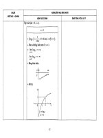
Try the following: set the dimension of the height of the square. The ‘Make
Dimension Driven?’ message appears:
You have entered too much information because:
- The dimension you added says the height is 60mm.
- The relation between the two lines you have created before says
the height is equal to the width, which is also 60.
The height is defined twice now, and this creates a conflict in SolidWorks.
You must resolve this inconsistency. In the menu that is shown above, the
best thing to do is choose ‘Cancel’. The dimension will not be set.
Did you make an over-defined sketch anyway? Then, throw away (delete)
dimensions and/or relations, so that the sketch is no longer over-defined.
SolidWorks for VMBO en MBO
Tutorial 5: Tic Tac Toe
6
6 Click on ‘Features’ in the
CommandManager, then
on ‘Extruded Boss/Base’.
1. Set the thickness of
the plate to 10 mm.
2. Click on OK.
7 Next, we will make a
sketch in which we deter-
mine the exact position of
the holes:
1. Select the top plane of
the plate
2. Click on the View
Orientation icon.
3. Click on Normal To.
8 Draw another rectangle
with a dimension of 46
mm. Follow the steps 3 to
5 again if you need help.
SolidWorks for VMBO en MBO
Tutorial 5: Tic Tac Toe
7
9 Click on ‘Exit Sketch’ in the
CommandManager.
We will not use this sketch
to make a feature.
10 Start up a new sketch.
1. Select the top plane
again.
2. Click on Circle in the
CommandManager.
3,4 Draw a circle like the
one in the illustration.
11 Set the dimension between
the circle and one of the
diagonal lines that you
have drew previously:
1. Click on Smart Dimen-
sion in the Command-
Manager.
2. Click on the center of
the circle.
3. Click on the diagonal
line.
4. Set the dimension.
5. Change it to 15mm.
6. Click on OK.
SolidWorks for VMBO en MBO
Tutorial 5: Tic Tac Toe
8
12 Next, set the dimension to
the other diagonal line
(15mm) and the diameter
of the circle (Ø8mm).
Push the <Esc> key to
close the Smart Dimension
command.
13 To set an exact fitting to
the hole (Ø8), execute the
following steps:
1. Select a dimension (it
turns green).
2. Be sure that ‘Toler-
ance/Precision’ is visi-
ble in the PropertyMa-
nager. Click on the
double arrows to re-
veal it.
3. Set Tolerance type to
‘Fit’.
4. Select a fitting of D10
in the Hole Fit field.
5. Click on OK.
Tip! In this and the following tutorials, we will be using the commands from the
CommandManager more often.
At this point, you should be getting used in working with SolidWorks and
might find it more convenient to use the quick menu. This quick menu can
be activated by pushing the ‘S’ on the keyboard. The most important and
most frequently used commands will appear. You will see the commands
and functions that are associated with the part of the menu in which you
are working, so you will see different commands/functions when you are in
a sketch mode than when you are in feature mode.
SolidWorks for VMBO en MBO
Tutorial 5: Tic Tac Toe
9
14 Make a hole in this sketch:
click on ‘Features’ in the
CommandManager and
then on ‘Extruded Cut’.
Set the depth of the hole in
the PropertyManager to
‘Through all’ and click on
OK.
15 We will complete the hole
pattern now.
1. Select the hole you just
created.
2. Click on the ‘Linear
pattern’ icon in the
CommandManager.
16 Next, set following fea-
tures:
1. Select ONE of the di-
agonal lines.
2. Check to make sure
that the line appears in
the selection field.
3. Set the distance be-
tween the copies to
15mm.
4. Set the number of cop-
ies to 3.
5. Whenever the copies
are placed on the
wrong side, click on
‘Reverse Direction’.
SolidWorks for VMBO en MBO
Tutorial 5: Tic Tac Toe
10
17 Repeat these steps in the
area named ‘Direction 2’.
For this purpose, select the
other diagonal line.
If the preview looks good
to you, click on OK.
18 We will now create the
mounting holes for the
bolts.
Click on ‘Hole Wizard’ in
the CommandManager.
SolidWorks for VMBO en MBO
Tutorial 5: Tic Tac Toe
11
19 Set the following features
in the PropertyManager:
1. Select the hole type
Counter bore.
2. Set the Standard:
‘ISO’.
3. Set Type: ‘Hex Socket
Head ISO 4762’.
4. Set Size: ‘M5’.
5. Click on the ‘Positions’
tab.
20 Next, click at the four cor-
ners of the sketch to posi-
tion the holes.
Click on OK.
SolidWorks for VMBO en MBO
Tutorial 5: Tic Tac Toe
12
21 The first part, the top
plate, is now ready. Save
this file as: Slab.SLDPRT.
Tip: make a new folder on
your computer first. You
can arrange all of the files
by product.
Work plan We will now create the second part, the bottom plate. We will do this in ac-
cordance with the drawing below.
Notice that this part looks very much like the first one. The perimeter di-
mensions and the position of the mounting holes are the same. That is why
we will create a configuration from the first part to produce the second one.
22 Click on the Configuration-
Manager tab.
SolidWorks for VMBO en MBO
Tutorial 5: Tic Tac Toe
13
23 The name of the configura-
tion is ‘Default’. Double-
click on this name to
change it to ‘Top’.
24 1. Click your right mouse
button on the upper
line in the Configura-
tionManager.
2. Select ‘Add Configura-
tion’ from the menu.
25 1. Set the name of the
new configuration to:
‘Bottom’.
2. Click on OK.
26 There are two configura-
tions in the list now: ‘Top’
(gray, non-active), and
‘Bottom’ (black, active).
We will work with the ac-
tive configuration.
Click on the FeatureMa-
nager tab.
SolidWorks for VMBO en MBO
Tutorial 5: Tic Tac Toe
14
27 Now Suppress the last
three features that you just
made:
1. Click on the feature
‘Extrude2’.
2. Hold the Shift key on
the keyboard and click
on the last feature.
3. Release the Shift key.
The last three features
are now selected, and
a small options menu
appears.
4. Select: Suppress in the
menu.
All holes have disappeared
from the model.
28 Next, we will make some
tapped holes with M5
thread.
Click on the ‘Hole Wizard’
in the CommandManager.
SolidWorks for VMBO en MBO
Tutorial 5: Tic Tac Toe
15
29 Select the hole type Tap in
the PropertyManager.
Make sure all settings are
equal to the settings in the
illustration at right.
Click on the ‘Positions’ tab.
30 Click on the four corners of
the sketch to position the
holes.
Click on OK.
SolidWorks for VMBO en MBO
Tutorial 5: Tic Tac Toe
16
31 Whenever no thread pat-
tern appears in the holes,
then change the following
settings:
1. Click the right mouse
button on ‘Annotations’
in the FeatureManager.
2. Select ‘Details’.
32 1. Make sure that the op-
tion ‘Shaded cosmetic
threads’ is checked.
2. Click on OK.
33 Next, we want to hide the
sketch we have used to
make the holes:
1. Click with the right
mouse button on the
‘Sketch’ in the Featu-
reManager.
2. Select Hide in the
menu.
SolidWorks for VMBO en MBO
Tutorial 5: Tic Tac Toe
17
34 Reactivate the configura-
tion of the top plate.
Click on the Configuration-
Manager tab.
35 Double-click on the confi-
guration ‘Top’ in the Confi-
gurationManager.
36 Save the file.
Work plan The third part is the cylinder. We will create this by using the dimensions of
the drawing below.
To be able to play Tic-Tac-Toe, we need to insert an ‘X’ or an ‘O’ at the top
of each cylinder. We will do this by making two configurations of the cy-
linder.
37 Open a new part.
SolidWorks for VMBO en MBO
Tutorial 5: Tic Tac Toe
18
38 Open a sketch in the Top
plane.
Draw a circle, with the cen-
ter on top of the origin.
Set a dimension Ø8.
39 Set the fitting to h9.
1. Select the dimension.
2. Set the Tolerance type
to fit in the Property-
Manager.
3. Set Shaft fit to h9.
40 1. Drag the height of the
extrusion to 20mm.
2. Click on OK.
SolidWorks for VMBO en MBO
Tutorial 5: Tic Tac Toe
19
41 We will now make an an-
gled edge at the top and at
the bottom of the cylinder
with the Chamfer com-
mand.
Click on ‘Chamfer’ in the
CommandManager.
42 1. Click on the vertical
outside plane of the
cylinder.
2. Set the sloped distance
to 1mm in the Proper-
tyManager.
3. Check the angle to be
45°.
4. Click on OK.
43 1. Select the top plane of
the cylinder.
2. Click on Sketch Text in
the CommandManager.
SolidWorks for VMBO en MBO
Tutorial 5: Tic Tac Toe
20
44 1. Type in the capital ‘X’
in the text field.
2. Uncheck the option
‘Use document font’.
3. Click on the ‘Font…’
button.
45 Check in the menu to make
sure the text height is set
to 4mm, and click on OK.
46 Click on OK in the Proper-
tyManager.
SolidWorks for VMBO en MBO
Tutorial 5: Tic Tac Toe
21
47 Rotate the model with the
Normal to command so
you can get a good view of
the sketch.
Drag the letter to the cen-
tre of the plane.
48 Click on ‘Features’ in the
CommandManager and
next on ‘Extruded Cut’.
49 1. Set the depth to
0.25mm.
2. Click on OK.
50 The cylinder with the ‘X’ is
now ready. Save the file
as: Shaft.SLDPRT.
SolidWorks for VMBO en MBO
Tutorial 5: Tic Tac Toe
22
51 To make the cylinder with
the ‘O’ we will use a
second configuration.
Click on the Configuration-
Manager tab.
52 Change the name of the
current configuration (‘De-
fault’) to ‘Shaft-X’.
Create a new configuration
called ‘Shaft-O’.
If necessary, compare
these commands to steps
24 to 26.
Check to make sure that
the configuration ‘Shaft-O’
is active (black).
Click on the FeatureMa-
nager tab.
53 With the ‘Shaft-O’ configu-
ration active, we must hide
the letter ‘X’.
1. Click on the last fea-
tures which you have
made.
2. Select Suppress in the
menu that appears.
SolidWorks for VMBO en MBO
Tutorial 5: Tic Tac Toe
23
54 Now, put a letter ‘O’ on the
top plane of the cylinder.
Do this in exactly the same
way as you did before with
the letter ‘X’ in steps 43 to
49.
55 Save the file.
Open a new assembly.
56 When you did not close the
two parts we just created
(Slab and Shaft) you will
see the image on the right.
1. Click on the file ‘Slab’.
2. Click on OK.
If you did close this file,
find it with the ‘Browse…’
command.
57 Click on ‘Insert Compo-
nents’ in the CommandMa-
nager.
SolidWorks for VMBO en MBO
Tutorial 5: Tic Tac Toe
24
58 Add the same part again.
Place it just below the first
one.
59 Next, we have to change
the configuration of the
bottom plate.
1. Click with the right
mouse button some-
where on the bottom
plate.
2. Select ‘Configure Com-
ponent’ in the menu
that appears.
60 1. Select the Configura-
tion ‘Bottom’.
2. Click on OK.
Tip! When a part is open while added to an assembly, you can only select the
desired configuration AFTER putting it in the assembly. That is what we
have just done.
When a part is closed, click on the PropertyManager and Browse to find it
(see step 56). In the menu that appears, you can select the right configura-
tion directly. Therefore, sometimes it is more convenient to use the Browse-
function anyway, even though the part is open.
SolidWorks for VMBO en MBO
Tutorial 5: Tic Tac Toe
25