SolidWorks Tutorial - Part 6 ppsx
Bạn đang xem bản rút gọn của tài liệu. Xem và tải ngay bản đầy đủ của tài liệu tại đây (1.06 MB, 33 trang )
SolidWorks
®
Tutorial 6
DRAWINGS OF THE TIC-TAC-TOE GAME
Preparatory Vocational Training
and Advanced Vocational Training
To be used with SolidWorks
®
Educational Release 2008-2009
SolidWorks for VMBO en MBO
Tutorial 6: Drawings of the Tic-tac-toe game
2
© 1995-2009, Dassault Systèmes SolidWorks Corp.
300 Baker Avenue
Concord, Massachusetts 01742 USA
All Rights Reserved
U.S. Patents 5,815,154; 6,219,049; 6,219,055
Dassault Systèmes SolidWorks Corp.is a Dassault Systèmes
S.A. (Nasdaq:DASTY) company.
The information and the software discussed in this document
are subject to change without notice and should not be consi-
dered commitments by Dassault Systèmes SolidWorks Corp.
No material may be reproduced or transmitted in any form or
by any means, electronic or mechanical, for any purpose
without the express written permission of Dassault Systèmes
SolidWorks Corp.
The software discussed in this document is furnished under a
license and may be used or copied only in accordance with
the terms of this license. All warranties given by Dassault
Systèmes SolidWorks Corp. as to the software and documen-
tation are set forth in the Dassault Systèmes SolidWorks
Corp. License and Subscription Service Agreement, and
nothing stated in, or implied by, this document or its contents
shall be considered or deemed a modification or amendment
of such warranties.
SolidWorks® is a registered trademark of Dassault Systèmes
SolidWorks Corp.
SolidWorks 2009 is a product name of Dassault Systèmes So-
lidWorks Corp.
FeatureManager® is a jointly owned registered trademark of
Dassault Systèmes SolidWorks Corp.
Feature Palette™ and PhotoWorks™ are trademarks of So-
lidWorks Corporation.
ACIS® is a registered trademark of Spatial Corporation.
FeatureWorks® is a registered trademark of Geometric Soft-
ware Solutions Co. Limited.
GLOBEtrotter® and FLEXlm® are registered trademarks of
Globetrotter Software, Inc.
Other brand or product names are trademarks or registered
trademarks of their respective holders.
COMMERCIAL COMPUTER
SOFTWARE - PROPRIETARY
U.S. Government Restricted Rights. Use, duplication, or dis-
closure by the government is subject to restrictions as set
forth in FAR 52.227-19 (Commercial Computer Software -
Restricted Rights), DFARS 227.7202 (Commercial Comput-
er Software and Commercial Computer Software Documen-
tation), and in the license agreement, as applicable.
Contractor/Manufacturer:
Dassault Systèmes SolidWorks Corp., 300 Baker Avenue,
Concord, Massachusetts 01742 USA
Portions of this software are copyrighted by and are the
property of Electronic Data Systems Corporation or its sub-
sidiaries, copyright© 2009
Portions of this software © 1999, 2002-2009 ComponentOne
Portions of this software © 1990-2009 D-Cubed Limited.
Portions of this product are distributed under license from
DC Micro Development, Copyright © 1994-2009 DC Micro
Development, Inc. All Rights Reserved.
Portions © eHelp Corporation. All Rights Reserved.
Portions of this software © 1998-2009 Geometric Software
Solutions Co. Limited.
Portions of this software © 1986-2009 mental images GmbH
& Co. KG
Portions of this software © 1996-2009 Microsoft Corpora-
tion. All Rights Reserved.
Portions of this software © 2009, SIMULOG.
Portions of this software © 1995-2009 Spatial Corporation.
Portions of this software © 2009, Structural Research &
Analysis Corp.
Portions of this software © 1997-2009 Tech Soft America.
Portions of this software © 1999-2009 Viewpoint Corpora-
tion.
Portions of this software © 1994-2009, Visual Kinematics,
Inc.
All Rights Reserved.
SolidWorks Benelux developed this tutorial for self-training with the SolidWorks 3D CAD program. Any other use
of this tutorial or parts of it is prohibited. For questions, please contact SolidWorks Benelux. Contact informa-
tion is printed on the last page of this tutorial.
Initiative: Kees Kloosterboer (SolidWorks Benelux)
Educational Advisor: Jack van den Broek (Vakcollege Dr. Knippenberg)
Realization: Arnoud Breedveld (PAZ Computerworks)
Drawings of the TIC-TAC-TOE game.
In this tutorial you will learn how to make a 2D drawing of a part that you have created in 3D. You must
have completed Tutorial 5 first and saved the files associated with it in order to complete this tutorial.
In this tutorial we will make the following drawings:
1. A drawing of the assembled parts.
2. A drawing of the bottom part, the base.
3. A drawing of the top part.
Work plan First, we will make an assembly drawing. We will use the top and side
views with a partly transparent side.
SolidWorks for VMBO en MBO
Tutorial 6: Drawings of the Tic-tac-toe game
3
1 Start SolidWorks and open
the assembly Tictac-
toe.SLDASM, which you
have made in the last tu-
torial.
2 Click on New in the Tool-
bar.
3 Click on ‘Advanced’ in the
menu that appears.
4 1. Select the template
‘sw-tutorial’ (Solid-
Works Tutorial).
2. Click on OK.
Whenever this template is
not available, ask your
teacher about it.
Do you work at home? If
so, you can download the
file templates.zip
from www.solidworks.nl
.
An explanation about
where to put your files is
included in the ZIP file.
SolidWorks for VMBO en MBO
Tutorial 6: Drawings of the Tic-tac-toe game
4
5 1. Select the file ‘Tictac-
toe’.
2. Click on ‘Next’.
6 1. Select ‘Single View’ in
the PropertyManager
(to place ONE view in
the drawing).
2. Select the Top View.
3. Position the view on
the drawing board.
SolidWorks for VMBO en MBO
Tutorial 6: Drawings of the Tic-tac-toe game
5
7 After you have positioned
the view, SolidWorks will
automatically start the
command ‘Projected View’.
Click beside the top view to
put a side view next to it.
Push the <Esc> key on
your keyboard to end this
command.
Tip! There are three commands for placing views on your drawing board:
Model View: this is used to place one of the main views in the drawing
field. This is actually the same method you used in steps 4 and 5.
Projected View: with this command you can extract a view using the
American or European projection method from the existing file.
Auxiliary View: this command is used to extract an auxiliary view from
the existing view and place it at a random angle to the main view.
With ‘Standard 3 View’ you will select the three main views (Top, Front,
and Right) with only one mouse click and place them on your drawing
board.
SolidWorks for VMBO en MBO
Tutorial 6: Drawings of the Tic-tac-toe game
6
8 1. Right-click at a random
position somewhere on
the drawing board (not
on a view!).
2. Select: ‘Properties’ in
the menu that appears.
9 1. Name the drawing:
‘Assembly’.
2. Set the scale to ‘2:1’ in
the menu that appears.
3. Select ‘Third angle’ for
‘Type of projection’:
4. Select the paper size
‘a3 – swtutorial’:
5. Click on OK.
Tip! In the Netherlands, the American projection is used for all technical draw-
ings and designs. This is called Third Angle Projection.
In most other European countries, the European projection method is used.
This is called First Angle Projection.
We will be using the Third Angle Projection, but of course you can choose
to use the First Angle Projection. The views will relate to on another in a
different way.
SolidWorks for VMBO en MBO
Tutorial 6: Drawings of the Tic-tac-toe game
7
10 When you move your cur-
sor over a view, a dotted
frame appears around the
view. With this frame, you
can drag the view to adapt
the way the views are posi-
tioned on the drawing
board.
Be sure the views are neat-
ly aligned in the middle of
the drawing board.
11 Next we a portion of the
side view transparent to
provide a clear view of the
hexagonal bolt.
1. Click on ‘Sketch’ in the
CommandManager.
2. Click on Spline.
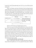
12 Draw a curve as shown in
the illustration on the right.
You will position several
random points in the draw-
ing. Try to copy the shape
as shown on the right.
Be sure the last point is in
the same position as the
first one. Only then will you
get a closed curve.
SolidWorks for VMBO en MBO
Tutorial 6: Drawings of the Tic-tac-toe game
8
13 Be sure the curve you have
just drawn is still selected
(green).
1. Click on ‘View Layout’
in the CommandMa-
nager.
2. Click on ‘Broken-out
Section’.
14 Next, set the features in
the menu that appears:
1. Check ‘Auto hatching’.
2. Check ‘Exclude fasten-
ers’.
3. Click on OK.
Tip! The menu you have seen in step 14 will always appear when you have
made a broken-out section from an assembly like we just did. You can set a
few items in this menu:
Auto hatching: this option makes sure that different parts are hatched in
different directions. When you fail to check this option, hatching occurs
without differences through all parts.
Excluded components: in the blue field, you can select parts to break
out.
Exclude fasteners: fasteners, like the hexagonal bolts in our drawing,
stay complete.
SolidWorks for VMBO en MBO
Tutorial 6: Drawings of the Tic-tac-toe game
9
15 1. Be sure that all three
options at the bottom
are checked (‘Preview’,
‘Auto hatching’ and
‘Exclude fasteners’).
2. Next click on the hole
of the hexagonal bolt.
In this way, you de-
termine the depth of
the break-out. The yel-
low line now goes
through the middle of
the circle.
3. If the preview looks all
right, click on OK to
finish it.
16 As you can now see, the
thread of the hexagonal
bolt and the base plate are
not shown. In an assembly
you must do as following:
1. Click on ‘Annotate’ in
the CommandManager.
2. Click on ‘Model Items’.
SolidWorks for VMBO en MBO
Tutorial 6: Drawings of the Tic-tac-toe game
10
17 Set the next features in the
PropertyManager:
1. Be sure to set all ‘Di-
mensions’ buttons OFF.
2. Check the Cosmetic
Thread in the ‘Annota-
tions’ field.
3. Select ‘Selected com-
ponent’ in the
‘Source/Destination’
field.
4. Uncheck the option
‘Import items into all
views’.
5. Click on the frame of
the view in the draw-
ing.
6. Click on the drawing of
the hexagonal bolt.
The thread features
are added at this point.
7. Click on OK.
18 As you can see, the thread
is also revealed at the bot-
tom hexagonal bolt (which
should not be visible. We
have to hide it:
1. Right-click on the
thread.
2. Click on ‘Hide’ in the
menu that appears.
3. Click beside the view
to check if the thread
turned invisible.
The thread is still visible,
because there are TWO
holes directly on top of
each other. Therefore, re-
peat steps 1 to 3.
Do the same for the thread
in the base plate.
19 Next, we are going to place
the centerlines in the top
view.
Click on ‘Center Mark’ in
the CommandManager.
SolidWorks for VMBO en MBO
Tutorial 6: Drawings of the Tic-tac-toe game
11
20 1. Be sure the first but-
ton (Single Center
Mark) in the Proper-
tyManager is checked
in the ‘Options’ field.
2-5. Click on the four holes
at the outer ends of
the base plate.
6. Click on OK.
21 Select the command ‘Cen-
ter Mark’ in the Com-
mandManager again. (Look
at step 19). Set the follow-
ing features in the Proper-
tyManager:
1. Click on the second
button in the ‘Op-
tions’ field. (Linear
Center Mark).
2-10. Click on the outer
circles of all nine cy-
linders.
11. Click on OK.
SolidWorks for VMBO en MBO
Tutorial 6: Drawings of the Tic-tac-toe game
12
22 1. Select the command
‘Centerline’ in the
CommandManager.
2,3 Next, click on the two
vertical sides of the
square. The vertical
centerline is placed in
the view.
4,5 Next, click on the two
horizontal sides to
place a centerline.
23 Next, we draw the center-
lines in the side view. Click
on the command ‘Center-
line’ again (look at step
22).
Click on the frame which is
around the view. All cen-
terlines are automatically
placed now.
Pay attention: if this does
not work, close the com-
mand and try again!
Tip! In step 23 we have placed all centerlines in a single action. This is very
SolidWorks for VMBO en MBO
Tutorial 6: Drawings of the Tic-tac-toe game
13
convenient of course, but sometimes we will get more centerlines then we
need. If this is the case, you can simply delete with the <Del> (delete) key
on your keyboard.
24 Now, we want to extend
the centerline that is in the
middle. Click on the center-
line and drag the ends a
bit, as shown in the illu-
stration.
25 Next, we will put a parts
list on the drawing board.
It is called a Bill of Mate-
rials.
1. Click on ‘Tables’ in the
CommandManager.
2. Click on ‘Bill of Mate-
rials’.
26 Click on one of the views.
SolidWorks for VMBO en MBO
Tutorial 6: Drawings of the Tic-tac-toe game
14
27 1. Uncheck the option ‘At-
tach to anchor point’ in
the PropertyManager.
2. Click on OK.
28 Place the parts list just
above the title block of the
drawing.
29 To adapt the size of the
parts list, do the following:
1. Click somewhere in the
parts list to select it.
Blue bars will appear
on the left and right.
2. Drag the left top cor-
ner from the parts list
to the desired position.
SolidWorks for VMBO en MBO
Tutorial 6: Drawings of the Tic-tac-toe game
15
30 Next, we will place part
numbers in the drawing.
1. Select the side view.
2. Click on ‘AutoBalloon’
in the CommandMa-
nager.
31 1. Select the option ‘Top’
in the ‘Balloon Layout’
tab in the PropertyMa-
nager.
2. Select the option ‘Bal-
loon Faces’.
3. Click on OK.
SolidWorks for VMBO en MBO
Tutorial 6: Drawings of the Tic-tac-toe game
16
32 Now, you can place the
parts numbers in their po-
sitions.
Click on every parts num-
ber. You can drag the
number balloon as well as
use the arrow now.
When you do not put the
point of an arrow on a line
of a figure, the arrowhead
will automatically turn into
a dot.
Try to position the parts
numbers as in the illustra-
tion on the right.
33 The composition drawing is
now ready, except for one
thing: you have to fill in
your name in the title
block.
1. Right-click somewhere
in the drawing (not on
a view).
2. Select ‘Edit Sheet For-
mat’ in the menu.
The drawing now tempora-
rily disappears, and you
can change the items in
the title block.
34 1. Double-click on the
text ‘Name:’, and fill in
your own name.
2. Click on OK.
SolidWorks for VMBO en MBO
Tutorial 6: Drawings of the Tic-tac-toe game
17
35 1. Right-click in the draw-
ing again.
2. Select ‘Edit Sheet’ in
the menu.
The drawing reappears.
36 Save the file as: Tictac-
toe.SLDDRW.
37 Next, we will make a single
drawing of the top plate.
We will first add a new
drawing.
Click on Add sheet at the
bottom of the screen.
Tip! We use Add Sheet to add a drawing sheet within the same file. Of course,
we could have created a second file, but in this way we will keep drawings
together and provide a better overview.
38 When the menu of step 39
does not appear by itself,
right-click somewhere in
the drawing and select
‘Properties’.
SolidWorks for VMBO en MBO
Tutorial 6: Drawings of the Tic-tac-toe game
18
39 Most of the settings for this
drawing will be the same
as the settings for the first
drawing. Therefore, there
is not much we have to
change.
1. Change the name of
the sheet to ‘Slab-top’.
2. Click on OK.
40 We will use the Task Pane
to place a view on the
drawing board
Click on the tab ‘View Pa-
lette’ in the Task Pane.
41 The views you see in the
‘View Palette’ bar, are the
ones that are in the as-
sembly. To load the top
plate, click on the Browse
(‘…’) button at the top of
the Task Pane.
SolidWorks for VMBO en MBO
Tutorial 6: Drawings of the Tic-tac-toe game
19
42 1. Click on the part
‘Slab.SLDPRT’.
2. Select the configura-
tion ‘Top’.
3. Click on ‘Open’.
43 In the View Palette (on the
right of the screen) the
views of the top plate are
visible now.
1. Drag the Top-view to
the drawing sheet.
2. Click to the right of
the top view to place
a side view.
3. Click on OK in the
PropertyManager.
Tip! Notice that the Center Marks of all holes have been added to the view au-
tomatically. In the drawing of an assembly, SolidWorks does not do this au-
tomatically. SolidWorks does this, however, in a drawing of a part, if this
feature is set.
SolidWorks has dozens of settings for creating drawings. We always pick
the standard settings, but it is possible that the settings on the computer
you are working on have been changed. Some features may look of even
work differently.
If you want to have a look at all the possible settings, click on Options in
the Standard Toolbar.
Click on the ‘Document Properties’ tab in the menu. Here, there are all
types of settings, including the option to place Center Marks automatically.
SolidWorks for VMBO en MBO
Tutorial 6: Drawings of the Tic-tac-toe game
20
44 Break open the side view
so you have a clear view of
the counter bore hole. Can
you remember how to do
this?
Check steps 11 to 15 of
this tutorial. You did the
same thing in the assem-
bly!
Put a centerline in the hole
(look at step 23).
45 We will draw a cross-cut
now.
1. Click on ‘View Layout’
in the CommandMa-
nager.
2. Click on ‘Section
View’.
46 Next, you have to draw the
cross-cut line.
Put the cursor directly
above the middle of the
top line in the top view but
do not click yet!
SolidWorks for VMBO en MBO
Tutorial 6: Drawings of the Tic-tac-toe game
21
47 Move the mouse upwards.
A blue dotted vertical aux-
iliary line appears.
Click just above the view
while this auxiliary line is
still visible.
48 Move your mouse straight
down and click just below
the view.
Tip! Why could you not just click on the middle of the top line in the view at
step 48?
When you would have done this, the cross-cut line would have stopped at
that point. The arrow and the letter to indicate the cross-cut section would
appear in the middle of the drawing and that is just not what we want to
have!
It is not possible to change this feature later. We have created the line as
described above, and it is possible to change the length.
49 Next click besides the side
view to place the cross-cut
drawing.
SolidWorks for VMBO en MBO
Tutorial 6: Drawings of the Tic-tac-toe game
22
50 Move the views in such a
way that they are placed
on the sheet neatly. Add
the centerlines in the
cross-cut drawing.
51 Finally, we have to add the
dimensions to this drawing.
1. Click on ‘Annotate’ in
the CommandManager.
2. Click on ‘Model Items’.
52 Set the following features
in the PropertyManager:
1. Select ‘Entire Mod-
el’ in the ‘Source’
field.
2. Check the options
Marked for Draw-
ing in the ‘Dimen-
sions’ tab.
3. Check the option
Hole Wizard Pro-
file.
4. Click on OK.
The dimensions will now
be placed in the drawing.
Tip! With the Model Items command you will put parts of the model in the
drawing. In this case we did that with the dimensions. We have checked
two options:
1. Marked for Drawing: these are often all of the dimensions that
you used when modeling the parts in sketches and when making
the features.
SolidWorks for VMBO en MBO
Tutorial 6: Drawings of the Tic-tac-toe game
23
2. Hole Wizard Profile: the shape of the hole you have made with
the Hole Wizard.
When adding dimensions to a drawing in SolidWorks, it is always very
smart to start with Model Items. Although by doing so, the drawing is not
finished yet! We will see that some dimensions are missing and other di-
mensions are in the wrong positions. You can change some items, but
some of them must be deleted and replaced.
53 First, we will adapt the di-
mensions located at the
outside edges of this part.
1. Select the dimension
60mm, and drag it
(when necessary) a bit
upwards, so it no long-
er crosses the center-
line.
2. Click on the square in
the ‘Dimension Text’
tab. The text in the
field now changes to
‘<MOD-BOX><DIM>’,
and a square appears
in the drawing in front
of the dimension of
60mm.
3. Click on OK.
SolidWorks for VMBO en MBO
Tutorial 6: Drawings of the Tic-tac-toe game
24
54 In the drawing, you will
see the dimension of
15mm four times. We want
to replace it with only one
dimension of 30 mm.
Select the four dimensions
(hold the <Ctrl> key on
the keyboard) and push
<Del> (delete).
You can also remove them
one at a time.
55 Next, we set the dimension
of 30 mm.
1. Click on ‘Sketch’ in the
CommandManager.
2. Click on Smart Dimen-
sion.
3,4 Click on the end of
two centerlines.
5. Set the dimension.
6. The dimension is still
selected (green). Click
on the square symbol
in the ‘Dimension
Text’ tab in the Pro-
pertyManager.
7. Click on OK.
SolidWorks for VMBO en MBO
Tutorial 6: Drawings of the Tic-tac-toe game
25