Cisco CCIP MPLS Study Guide phần 2 ppsx
Bạn đang xem bản rút gọn của tài liệu. Xem và tải ngay bản đầy đủ của tài liệu tại đây (2.04 MB, 49 trang )
MPLS Label Switching 15
Label-Switched Paths
Now let’s take a look at the label-switched paths. A label-switched path (LSP)
is a unidirectional set of LSRs that the labeled packet must flow through in
order to get to a particular destination.
Let’s say that the user on PE1 wants to ping the loopback address of PE2.
So, the user types ping 192.168.1.4.
By looking at the labels in the following output of PE1, you can see
the outbound label that will be used is 28 and it will be sent out
Serial 0/0:
PE1#show mpls forwarding-table
Local Outgoing Prefix Bytes tag Outgoing Next Hop
tag tag or VC or Tunnel Id switched interface
27 27 192.168.1.16/30 0 Se0/0 point2point
28 28 192.168.1.4/32 0 Se0/0 point2point
29 Pop tag 192.168.1.2/32 0 Se0/0 point2point
30 29 192.168.1.3/32 0 Se0/0 point2point
32 Pop tag 192.168.1.12/30 0 Se0/0 point2point
If a labeled packet of 28 arrives on P1, it will be sent out Serial 0/1 with
an outbound label of 27, as the following output shows:
P1#show mpls forwarding-table
Local Outgoing Prefix Bytes tag Outgoing Next Hop
tag tag or VC or Tunnel Id switched interface
27 Pop tag 192.168.1.16/30 0 Se0/1 point2point
28 27 192.168.1.4/32 0 Se0/1 point2point
29 Pop tag 192.168.1.3/32 0 Se0/1 point2point
31 Pop tag 192.168.1.1/32 0 Se0/0 point2point
If a labeled packet of 27 arrives on P2, it will be sent out Serial 0/1
unlabeled. The Pop tag, which you can see from the show mpls forwarding-
table command on P2, means, “Don’t send this traffic as labeled, but
instead send it as unlabeled IP traffic.” You can think of Pop tag as meaning,
“The next hop router needs to do a Layer 3 lookup on the packet” or “The
next hop router is the destination network or has a connected interface that
is in the destination network.” The official name for this process is called
penultimate hop popping.
Simpo PDF Merge and Split Unregistered Version -
Copyright ©2002 SYBEX, Inc., Alameda, CA
www.sybex.com
16 Chapter 1
An Introduction to MPLS
The word penultimate means “next to last.” With penultimate hop pop-
ping, the penultimate router in an LSP pops the label and forwards the
packet as unlabeled IP to the next hop router.
In this example, the next-to-last router (P2) in the LSP pops the label
and forwards the unlabeled packet to its ultimate destination (PE2), as the
following output demonstrates:
P2#show mpls forwarding-table
Local Outgoing Prefix Bytes tag Outgoing Next Hop
tag tag or VC or Tunnel Id switched interface
27 Pop tag 192.168.1.4/32 26224 Se0/1 point2point
28 Pop tag 192.168.1.2/32 29568 Se0/0 point2point
30 Pop tag 192.168.1.8/30 0 Se0/0 point2point
31 31 192.168.1.1/32 0 Se0/0 point2point
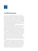
Figure 1.9 shows the LSP from PE1 to PE2.
FIGURE 1.9 The LSP from PE1 to PE2
Now let’s now see what happens when a user on PE1 wants to ping the
loopback address of PE2. The user types ping 192.168.1.3.
By looking at the labels of PE1 in the following output, you can see the
outbound label that will be used is 29, and it will be sent out Serial 0/0:
PE1#show mpls forwarding-table
Local Outgoing Prefix Bytes tag Outgoing Next Hop
tag tag or VC or Tunnel Id switched interface
27 27 192.168.1.16/30 0 Se0/0 point2point
28 28 192.168.1.4/32 0 Se0/0 point2point
29 Pop tag 192.168.1.2/32 0 Se0/0 point2point
30 29 192.168.1.3/32 0 Se0/0 point2point
32 Pop tag 192.168.1.12/30 0 Se0/0 point2point
IP 28 IP 27 IP
CE1 CE2
PE1 P1 P2 PE2
Serial 0 Serial 0
Serial 0/1 Serial 0/1
Serial 0/0
Serial 0/0
Serial 0/1
Serial 0/1
Serial 0/0
Serial 0/0
Simpo PDF Merge and Split Unregistered Version -
Copyright ©2002 SYBEX, Inc., Alameda, CA
www.sybex.com
MPLS Applications 17
If a labeled packet of 29 arrives on P1, it will be sent out Serial 0/1 as an
unlabeled IP packet, as you can see in the following output:
P1#show mpls forwarding-table
Local Outgoing Prefix Bytes tag Outgoing Next Hop
tag tag or VC or Tunnel Id switched interface
27 Pop tag 192.168.1.16/30 0 Se0/1 point2point
28 27 192.168.1.4/32 0 Se0/1 point2point
29 Pop tag 192.168.1.3/32 0 Se0/1 point2point
31 Pop tag 192.168.1.1/32 0 Se0/0 point2point
What about a ping to the Serial 0/0 interface of P2 (192.168.1.13)? By look-
ing at the labels of PE1, you can see that the packet will be sent out Serial 0/0
as an unlabeled IP packet, as you can see in the following output:
PE1#show mpls forwarding-table
Local Outgoing Prefix Bytes tag Outgoing Next Hop
tag tag or VC or Tunnel Id switched interface
27 27 192.168.1.16/30 0 Se0/0 point2point
28 28 192.168.1.4/32 0 Se0/0 point2point
29 Pop tag 192.168.1.2/32 0 Se0/0 point2point
30 29 192.168.1.3/32 0 Se0/0 point2point
32 Pop tag 192.168.1.12/30 0 Se0/0 point2point
Notice that the network in question is 192.168.1.12. Router P1 has a
directly connected interface into this network and therefore does not need a
labeled packet. Remember that penultimate hop popping is a time-saving
mechanism.
MPLS Applications
One of the basic principles of MPLS is that packets are switched
instead of routed. When a packet enters the service provider network from
a customer, it is unlabeled IP. The router at the edge of the service provider
network accepts the incoming unlabeled packet and applies a label.
The newly labeled packet follows an LSP through the service provider net-
work and is label-switched, not forwarded. When the packet leaves the
MPLS-enabled service provider network, the label is removed and it again
becomes an unlabeled IP packet. This process is illustrated in Figure 1.10.
Simpo PDF Merge and Split Unregistered Version -
Copyright ©2002 SYBEX, Inc., Alameda, CA
www.sybex.com
18 Chapter 1
An Introduction to MPLS
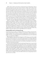
You can see that the label is attached to the packet by the PE1 router as it
enters the service provider network and is removed by the PE2 router as it is
routed to the customer network.
FIGURE 1.10 The MPLS process
Figure 1.10 is a logical, and not exact, representation of what happens to an
IP packet as it moves through an MPLS-enabled service provider network.
Since packets receive labels at the edge of the network by the edge-LSR,
and those labels are used by every LSR in the service provider network to
switch traffic, many applications exist for MPLS, such as MPLS virtual
private networks (VPNs), traffic engineering, and QoS.
MPLS and ATM
By turning a standard ATM Forum ATM switch into an ATM label switch
router (ATM-LSR), it is possible to merge the ATM and IP worlds to provide
end-to-end solutions. An ATM-LSR is an ATM switch that is capable of
forwarding packets based on labels.
Chapter 3 provides more detail about implementing MPLS in an ATM network.
Overlay
When an ATM switch is enabled as an ATM-LSR, an overlay between
service provider edge devices is no longer necessary. In Figure 1.8, all of the
POP routers are edge-LSRs, and all the ATM switches are ATM-LSRs. Since
IP L IP L IP L
IPIP
CE1 CE2
PE1 P1 P2 PE2
Serial 0 Serial 0
Serial 0/1 Serial 0/1
Serial 0/0
Serial 0/0
Serial 0/1
Serial 0/1
Serial 0/0
Serial 0/0
Simpo PDF Merge and Split Unregistered Version -
Copyright ©2002 SYBEX, Inc., Alameda, CA
www.sybex.com
MPLS Applications 19
every router in the network is running an Interior Gateway Protocol (IGP)
such as Open Shortest Path First (OSPF) or Intermediate System-Intermediate
System (IS-IS), POP routers now peer with ATM-LSRs directly instead of
with each other in a full mesh.
As packets enter the network as unlabeled IP, the edge-LSR labels the
packet and forwards it along the LSP. Figure 1.10 shows the labeled packet
as it traverses the service provider network. The actual process is a little more
complex than this example illustrates, but I want you to notice two very
important areas in Figure 1.10:
Instead of an overlay, routers are directly connected to ATM-LSRs.
Scalability is achieved by eliminating the need for a full mesh of VCs
and reducing the numbers of neighbors that must be maintained by a
routing protocol.
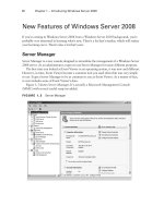
In Figure 1.11, packets enter the network as unlabeled IP. In this
figure, the edge-LSR is in Raleigh, and it accepts the unlabeled IP
packet and applies a label. Each ATM-LSR in the LSP uses the label to
move packets.
FIGURE 1.11 MPLS-enabled service provider network
Quality of Service
MPLS addresses QoS by allowing packets to be classified at the network
edge. Standard IP packets enter the network at an edge-LSR. The Experi-
mental (EXP) field of the MPLS label stack is used to hold QoS information
for use by MPLS-enabled devices along the LSP.
IP
IP L IP L IP L
Raleigh Atlanta
Raleigh ATM Atlanta ATM
Miami ATM Orlando ATM
Miami Orlando
Simpo PDF Merge and Split Unregistered Version -
Copyright ©2002 SYBEX, Inc., Alameda, CA
www.sybex.com
20 Chapter 1
An Introduction to MPLS
The Experimental field is three bits in size. With three bits, a total of
eight values are possible, but only six values are available for QoS. (The
remaining two values are reserved for internal network use only.) The default
operation is for the IP precedence value to be copied into the EXP field of
the MPLS label stack. Table 1.2 shows the mappings of IP precedence to
MPLS EXP.
With packets being classified at the network edge, it’s easier to provide
for enforceable service-level agreements (SLAs). Queuing methods such as
WRED and WFQ can be configured to operate using the EXP value in the
MPLS label stack. With MPLS, every device in the network can enforce a
consistent QoS policy regardless of whether they are routers or ATM
switches.
Traffic Engineering
Routing protocols, by their use of metrics, attempt to determine the best
(fastest) path for traffic to travel. For example, Figure 1.12 illustrates a
simple routed network with various link speeds. In this figure, the objects R1
through R8 represent routers in the network, and the connections OC3 and
OC12 represent the speed of the links between them.
TABLE 1.2 Experimental-to-IP Precedence Mappings
Experimental IP Precedence Class
77Reserved
66Reserved
55Real-time
44
33
22
11Best effort
Simpo PDF Merge and Split Unregistered Version -
Copyright ©2002 SYBEX, Inc., Alameda, CA
www.sybex.com
MPLS Applications 21
FIGURE 1.12 A simple traffic-engineering network
What is the best path for traffic to flow from R1 to R7? If the routing
protocol is using bandwidth as a metric, then traffic will follow the path of
R1 to R4 to R5 to R6 to R7, as shown in Figure 1.13.
FIGURE 1.13 Traffic flow from R1 to R7
What if traffic is coming from R8 to R1? The best path from the perspec-
tive of a routing protocol is from R8 to R6 to R5 to R4 to R1, as shown in
Figure 1.14.
FIGURE 1.14 Traffic flow from R8 to R1
What about traffic coming from R7 destined for R1? Well, when the
packet arrives at R6, it is sent along the same path as traffic from R8 to R1.
From the routing protocol’s perspective, the best path is from R7 to R6 to R5
to R4 to R1, as shown in Figure 1.15.
OC3 OC3 OC3
OC3
OC12
OC12
OC12 OC3
R1
R6
R2 R3 R7
R4 R5 R8
OC3 OC3 OC3
OC3
OC12
OC12
OC12 OC3
R1
R6
R2 R3 R7
R4 R5 R8
R1 R6
R2 R3 R7
R4 R5 R8
Simpo PDF Merge and Split Unregistered Version -
Copyright ©2002 SYBEX, Inc., Alameda, CA
www.sybex.com
22 Chapter 1
An Introduction to MPLS
FIGURE 1.15 Traffic flow from R7 to R1
Take a moment and look back at Figures 1.13, 1.14, and 1.15. Which
routers are continually traversed regardless of source, destination, or direc-
tion? You should notice that R1, R4, R5, and R6 are continually used to
move traffic across the network.
Traffic Engineering and Routing Protocols
If you are not a lord-high super-guru of routing, then there are a few issues
that you should be aware of. First of all, with all the traffic being sent along
the same path, it is possible for those links to become saturated. When a
link becomes saturated, packets will be dropped. The alternate path (R1 to
R2 to R3 to R4) will not be used.
Routing protocols find the best path to move the packet across the
network. Routing protocols such as OSPF and IS-IS, which are used in the
core of service provider networks, do not support unequal cost load balanc-
ing. In other words, even though there are two possible paths to get across
the network, the routing protocol will only use one of them based on the
metrics in use.
There is a little magic that you can do with routing protocols to try to make
two unequal paths look equal. If the routing protocol has two equal routes
across a network, it will load-balance. Be forewarned though: If you dabble
in the black art of routing protocol manipulation and try to do this in a large
network, it will become too much to manage.
Additionally, you could try to do some special policy-based routing. If you
do this on your core routers, it will slow them down. You also might not
want the job of managing such a solution.
R1 R6
R2 R3 R7
R4 R5 R8
Simpo PDF Merge and Split Unregistered Version -
Copyright ©2002 SYBEX, Inc., Alameda, CA
www.sybex.com
MPLS Applications 23
Which routers are never used to move user traffic across the network?
You should notice in Figures 1.13, 1.14, and 1.15 that routers R2 and R3 are
simply not used. To illustrate this, Table 1.3 describes the utilization of each
of the links in this network.
You can see that half of the links that are being paid for are used and
half of the links that are being paid for are not being used. This problem is
referred to as the fish. If you look at Figure 1.16, you can see why it is called
the fish.
FIGURE 1.16 The fish
TABLE 1.3 Link Utilization
Link Usage
R1 to R4 Utilized
R4 to R5 Utilized
R5 to R6 Utilized
R1 to R2 Not Utilized
R2 to R3 Not Utilized
R3 to R4 Not Utilized
R1 R6
R2 R3 R7
R4 R5 R8
Simpo PDF Merge and Split Unregistered Version -
Copyright ©2002 SYBEX, Inc., Alameda, CA
www.sybex.com
24 Chapter 1
An Introduction to MPLS
The MPLS solution is to use traffic-engineered tunnels that are made
possible with label stacking. Figure 1.17 shows two tunnels. On R6, two
tunnels, both with a destination of R1, are configured to load-share. The
first tunnel takes a path from R6 to R5 to R4 to R1. The second tunnel
follows the path from R6 to R3 to R2 to R1. Since MPLS supports unequal
cost load balancing, traffic will be load-balanced now across these two
tunnels on a per-packet basis. Tunnels are unidirectional, so a second set
of tunnels would need to be set up from R1 to R6 to support traffic flow
in the opposite direction from the example. Since tunnels are unidirectional in
nature, it’s possible for the return tunnel from R1 to R6 to take a completely
different path that’s based on the tunnel constraints.
FIGURE 1.17 Traffic-engineered network with tunnels
Another application for MPLS is VPNs. A discussion of VPNs begins in
Chapter 4, “VPNs: An Overview.”
Summary
There are many problems experienced by service providers when
trying to implement end-to-end solutions using two dissimilar technologies:
ATM and IP. MPLS evolved out of early attempts at solutions to glue the IP
Tunnel 1
Tunnel 2
R1
R6
R2 R3 R7
R4 R5 R8
Simpo PDF Merge and Split Unregistered Version -
Copyright ©2002 SYBEX, Inc., Alameda, CA
www.sybex.com
Exam Essentials 25
and ATM worlds together. Cisco’s proprietary solution, tag switching, later
became standardized into what we now know as MPLS.
Frame-mode MPLS uses a 32-bit label stack, referred to as a shim header,
because it is placed between the Layer 2 header and the Layer 3 payload.
An MPLS-capable router or switch label-switches packets instead of routing
them traditionally.
The MPLS architecture consists of two components: the control plane and
the forwarding or data plane. These two components make label switching
possible. The control plane binds labels to FECs. With CEF, label switching is
made possible in the forwarding plane with the FIB and LFIB.
As packets enter the service provider network, an edge-LSR imposes
a label. The label is used by every LSR along the LSP to label-switch the
packet. By labeling at the network edge, it is possible to classify packets and
implement consistent QoS throughout the network. Traffic engineering is
made possible with label stacking.
Exam Essentials
Understand the MPLS label stack. The MPLS label stack is a total of
32 bits. The label itself is 20 bits. The label stack is placed between the
Layer 2 header and the Layer 3 payload and is referred to as a shim header.
Know the MPLS architecture. The MPLS architecture is divided into
two planes: control and forwarding. The control plane is responsible for
binding labels to routes, or more specifically, to FECs. The forwarding
plane (also known as the data plane) operates like a big cache by main-
taining the FIB and LFIB. The control plane builds the bindings and the
forwarding plane actually uses those bindings to switch packets. Don’t
forget, CEF must be enabled for MPLS to work.
Be able to identify MPLS operation. Packets enter the service pro-
vider network as unlabeled IP. An edge-LSR imposes a label and
forwards the newly labeled packet to the next LSR along an LSP. Each
LSR along the LSP label-switches the packet. The next-to-last router
in the path pops the label through a mechanism called penultimate hop
popping.
Simpo PDF Merge and Split Unregistered Version -
Copyright ©2002 SYBEX, Inc., Alameda, CA
www.sybex.com
26 Chapter 1
An Introduction to MPLS
Know MPLS applications. First of all, MPLS changes network design
by eliminating the need for an overlay. Performance is improved because
packets are switched instead of routed. QoS can be implemented end to
end by having an edge-LSR classify packets and map a value to the Exper-
imental (EXP) field of the MPLS label stack. Traffic engineering is made
possible through label stacking and traffic-engineered tunnels.
Key Terms
Before you take the exam, be certain you are familiar with the follow-
ing terms:
ATM label switch router
(ATM-LSR)
label forwarding information
base (LFIB)
Cisco Express Forwarding (CEF) label information base (LIB)
control plane label switch router (LSR)
data plane label-switched path (LSP)
edge label switch router (edge-LSR) MPLS label stack
forwarding equivalence class (FEC) penultimate hop popping
forwarding information base (FIB) shim header
forwarding plane Tag Distribution Protocol (TDP)
Label Distribution Protocol (LDP) traffic engineering
Simpo PDF Merge and Split Unregistered Version -
Copyright ©2002 SYBEX, Inc., Alameda, CA
www.sybex.com
Review Questions 27
Review Questions
1. What command do you use to display the labels on a Cisco IOS router/
switch using MPLS?
A. show mpls ip
B. show mpls forwarding-table
C. show tag forwarding-table
D. show mpls labels
2. How many octets are there in the MPLS label stack header?
A. 1
B. 2
C. 3
D. 4
3. In frame-mode MPLS, the MPLS label stack resides ___________ and
___________. (Choose two.)
A. Before the Layer 2 header
B. After the Layer 2 header
C. Before the Layer 3 payload
D. After the Layer 3 payload
4. How many bits make up the label portion of the MPLS label stack?
A. 3
B. 16
C. 20
D. 32
Simpo PDF Merge and Split Unregistered Version -
Copyright ©2002 SYBEX, Inc., Alameda, CA
www.sybex.com
28 Chapter 1
An Introduction to MPLS
5. What command do you use to display the labels on a Cisco IOS router/
switch using tag switching?
A. show ip mpls
B. show mpls forwarding-table
C. show tag forwarding-table
D. show mpls labels
6. An MPLS-capable router/switch is called a(n) ___________?
A. LSA
B. LSR
C. LRR
D. TSR
7. Which device in the network only connects to service provider
equipment?
A. P
B. PE
C. CE
D. C
8. Which network device typically imposes the labels?
A. P
B. PE
C. CE
D. C
9. What is the process of removing a label by the next-to-last router
called?
Simpo PDF Merge and Split Unregistered Version -
Copyright ©2002 SYBEX, Inc., Alameda, CA
www.sybex.com
Review Questions 29
A. Popping
B. Fast switch popping
C. Penultimate hop popping
D. Label disposition
10. Which field of the MPLS label stack is used for Quality of
Service (QoS)?
A. Label
B. Experimental
C. S
D. TTL
11. Which of the following is not a suitable application for MPLS?
A. Quality of Service
B. Virtual private networks
C. Routing protocol replacement
D. Traffic engineering
12. In MPLS, VPNs and traffic engineering are made possible by ______.
(Choose the most appropriate answer.)
A. Label stacking
B. Label popping
C. Label imposition
D. Label switching
13. Cisco’s proprietary version of MPLS is called ___________.
A. Multi-protocol tag switching
B. Multi-Protocol Label Switching
C. Tag forwarding
D. Tag switching
Simpo PDF Merge and Split Unregistered Version -
Copyright ©2002 SYBEX, Inc., Alameda, CA
www.sybex.com
30 Chapter 1
An Introduction to MPLS
14. Which protocol does tag switching use to exchange tags with neighbors?
A. LDP
B. LIB
C. TDP
D. FIB
15. Which protocol does MPLS use to exchange labels with neighbors?
A. LDP
B. LIB
C. TDP
D. FIB
16. For MPLS or tag switching to work, ___________ must be enabled.
A. LFIB
B. LIB
C. FIB
D. CEF
17. To indicate the bottom of a stack, the S bit is set to ___________.
A. 0
B. 1
C. 2
D. None of the above
18. An IP prefix is analogous to a(n) ___________.
A. FIB
B. LFIB
C. FEC
D. CEF
Simpo PDF Merge and Split Unregistered Version -
Copyright ©2002 SYBEX, Inc., Alameda, CA
www.sybex.com
Review Questions 31
19. LSPs are ___________.
A. Unidirectional
B. Bi-directional
C. None of the above
20. An ATM switch that is MPLS-enabled is called a(n) ___________.
A. ATM-LSR
B. Edge-LSR
C. ATMF-LSR
D. Core-LSR
Simpo PDF Merge and Split Unregistered Version -
Copyright ©2002 SYBEX, Inc., Alameda, CA
www.sybex.com
32 Chapter 1
An Introduction to MPLS
Answers to Review Questions
1. B. The command to display label bindings in an MPLS environment
is show mpls forwarding-table.
2. D. The MPLS label stack header is 32 bits in total size, or 4 octets.
3. B, C. The MPLS label stack is often referred to as a shim header
because it resides between the Layer 2 header and Layer 3 payload.
4. C. The label portion of the MPLS label stack is 20 bits in length.
5. C. The command to display label bindings in a tag-switching
environment is show tag forwarding-table.
6. B. The correct terminology for an MPLS-capable router/switch is
that of a label switch router (LSR).
7. A. Network devices under control of the service provider and that
only connect to other provider devices are called P devices.
8. B. Labels enter the service provider network as unlabeled IP. The PE,
which is an edge-LSR, imposes a label.
9. C. To improve performance, the penultimate (next-to-last) router in
the LSP pops the label and forwards it to the next hop router as an
unlabeled packet.
10. B. The Experimental (EXP) field of the MPLS label stack is used for
QoS. Packets enter the network as unlabeled IP. An edge-LSR applies
the label and can set a value in the Experimental field that is used for
QoS by other LSRs.
11. C. The major applications for MPLS are QoS, VPNs, and traffic
engineering. An argument could be made that MPLS changes how
routing protocols are used by service providers, but MPLS does not
replace the need for them.
12. A. The ability to stack labels makes traffic engineering possible in
MPLS networks. Label stacking also makes MPLS VPNs possible.
13. D. Cisco’s proprietary way of moving tagged packets through a
network is called tag switching.
14. C. The proprietary protocol used by Cisco tag switching to exchange
tags is Tag Distribution Protocol (TDP).
Simpo PDF Merge and Split Unregistered Version -
Copyright ©2002 SYBEX, Inc., Alameda, CA
www.sybex.com
Answers to Review Questions 33
15. A. The protocol used by MPLS to exchange labels is Label Distri-
bution Protocol (LDP).
16. D. Cisco Express Forwarding (CEF) creates an optimized, “cached”
version of the routing table. CEF is a requirement for MPLS and tag
switching.
17. B. A value of 1 in this field indicates the bottom, or last label, of
the stack.
18. C. An FEC is a grouping of IP packets that are treated the same way.
For unicast-based routing, an IP prefix is the equivalent of an FEC.
19. A. A label-switched path (LSP) is a unidirectional set of label switch
routers (LSRs) that a labeled packet must flow through.
20. A. The proper term for an ATM switch that is MPLS-enabled is
ATM-LSR.
Simpo PDF Merge and Split Unregistered Version -
Copyright ©2002 SYBEX, Inc., Alameda, CA
www.sybex.com
Chapter
2
Frame-Mode MPLS
CCIP MPLS EXAM TOPICS COVERED IN
THIS CHAPTER:
Identify the IOS commands and their proper syntax used
to configure MPLS on frame-mode MPLS interfaces on
IOS platforms.
Describe the label distribution process between LSRs.
Describe frame-mode MPLS and cell-mode MPLS.
Identify the IOS commands and their proper syntax used
to configure advanced core MPLS features (TTL propagation,
controlled label distribution) on IOS platforms.
Identify the IOS commands and their proper syntax used
to monitor operations and troubleshoot typical MPLS failures
on IOS platforms.
Simpo PDF Merge and Split Unregistered Version -
Copyright ©2002 SYBEX, Inc., Alameda, CA
www.sybex.com
C
hapter 1, “An Introduction to MPLS,” introduced you to the
basic operation of MPLS. You learned that with MPLS, packets are switched
instead of routed. Unlabeled IP packets enter the service provider network at
the edge, and a label is applied. Every label switch router (LSR) in the label-
switched path (LSP) uses that label to label-switch the packet.
This chapter will build on what you already know, adding a little more
detail. This chapter starts with a review of traditional Layer 3 routing. To
really understand MPLS, you need a solid understanding of Layer 3 routing.
After routing, this chapter takes you though frame-mode MPLS step by
step in the “Frame-Mode MPLS Working Example” section. This section
builds on the concepts introduced in the previous chapter and focuses on the
interaction between MPLS and the routing protocols in the network. If you
are not comfortable with LSPs, go back and re-read that section of Chapter 1.
Labels and how they are bound to routes are described in greater detail in
the “Label Distribution” section. Again, if there are any concepts that you
are not totally comfortable with, make sure to re-read Chapter 1’s descrip-
tion of labels.
Finally, this chapter will explain troubleshooting and network verifica-
tion using configurations and output from a simple network.
Routing Review
Y
ou might be thinking to yourself, “I don’t need to read this section on
routing,” or “I already know all about routing.” Well, you might already
know Layer 3 routing, but please read this section carefully anyway. If the
ideas discussed here are somewhat new, take the time to really understand
everything you’re reading. If your routing skills are rusty, you may have dif-
ficulty understanding the interaction of MPLS and routing protocols.
Simpo PDF Merge and Split Unregistered Version -
Copyright ©2002 SYBEX, Inc., Alameda, CA
www.sybex.com
Routing Review
37
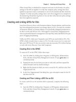
So, let’s do a quick and dirty review of routing. Figure 2.1 illustrates a
simple Layer 3 routed network that you’ll use for this review.
FIGURE 2.1
A sample network for Layer 3 routing
The IP and MAC addresses for each device in Figure 2.1 are listed in
Table 2.1 and Table 2.2.
TABLE 2.1
Host Addresses
Host A Host B
IP address 192.168.1.10 192.168.3.10
Subnet mask 255.255.255.0 255.255.255.0
Default gateway 192.168.1.1 192.168.3.1
Mac address AAAA-AAAA-AAAA BBBB-BBBB-BBBB
TABLE 2.2
Router Addresses
Router 1 Router 2
IP address (Ethernet0) 192.168.1.1 192.168.2.2
Subnet mask (Ethernet0) 255.255.255.0 255.255.255.0
MAC address (Ethernet0) 1111-1111-1111 2222-2222-2222
IP address (Ethernet1) 192.168.2.1 192.168.3.1
Subnet mask (Ethernet1) 255.255.255.0 255.255.255.0
MAC address (Ethernet1) 3333-3333-3333 4444-4444-4444
Ethernet0 Ethernet0Ethernet1 Ethernet1
Router 1 Router 2
Host A Host B
Simpo PDF Merge and Split Unregistered Version -
Copyright ©2002 SYBEX, Inc., Alameda, CA
www.sybex.com
38
Chapter 2
Frame-Mode MPLS
To begin this example, let’s say that Host A wants to send some packets
to Host B. The first thing that Host A does is determine whether Host B is
local (on the same subnet) or remote (on a different subnet). Host A, by com-
paring its network at 192.168.1.0 to that of Host B at 192.168.3.0, can see
that the network portions of the IP addresses do not match, meaning that
Host B is remote. Host A, now knowing that Host B is remote, puts a frame
on the wire destined for the default gateway. Table 2.3 shows the Layer 2
and Layer 3 information as placed on the wire.
As you look over this example, pay close attention to the source and destina-
tion IP addresses.
Router 1 knows that the frame is destined for it because it sees its own
Ethernet0 MAC address in the destination field in the frame. Router 1 picks
the frame up off the wire, discards the Layer 2 information, and looks in the
destination part of the Layer 3 header. Router 1, knowing that the packet
is destined for network 192.168.3.0, does a Layer 3 lookup and checks its
routing table to see if it has an entry for 192.168.3.10. It finds a route to
network 192.168.3.0/24 with a next hop of 192.168.2.2 via interface
Ethernet1. The following output is the routing table as it exists on Router 1:
Router1#
show ip route
R 192.168.3.0/24 [120/1] via 192.168.2.2, 00:00:01, Ethernet1
C 192.168.1.0/24 is directly connected, Ethernet0
C 192.168.2.0/24 is directly connected, Ethernet1
TABLE 2.3
Layer 2 and Layer 3 Information from Host A to Router 1
From Host A to Router 1
Layer 3 source 192.168.1.10
Layer 3 destination 192.168.3.10
Layer 2 source MAC AAAA-AAAA-AAAA
Layer 2 destination MAC 1111-1111-1111
Simpo PDF Merge and Split Unregistered Version -
Copyright ©2002 SYBEX, Inc., Alameda, CA
www.sybex.com
Routing Review
39
Router 1 knows that to get to network 192.168.3.0, it needs to send the
packet out of Ethernet1 to 192.168.2.2. Router 1 programmatically moves
the packet to the outbound Ethernet1 interface, creates a new frame, and
places the new frame on the wire. Table 2.4 lists the Layer 2 and Layer 3
information as it is placed on the wire from Router 1 to Router 2.
Notice in Table 2.4 that only the Layer 2 source and destination MAC addresses
have changed. The Layer 3 information is unchanged.
Router 2 knows that the frame is destined for it because it sees its own
Ethernet0 MAC address in the destination field in the frame. Router 2 picks
the frame up off the wire, discards the Layer 2 information, and looks in the
destination part of the Layer 3 header. Router 2, knowing that the packet
is destined for 192.168.3.10, does a Layer 3 lookup and checks its routing
table to see if it has an entry for 192.168.3.10. It finds a route to network
192.168.3.0/24 with a directly connected interface of Ethernet1. The follow-
ing output is the routing table as it exists on Router 2:
Router2#
show ip route
R 192.168.1.0/24 [120/1] via 192.168.2.1, 00:00:06, Ethernet0
C 192.168.2.0/24 is directly connected, Ethernet0
C 192.168.3.0/24 is directly connected, Ethernet1
Router 2 knows that to get to network 192.168.3.0, it needs to go out the
directly connected interface Ethernet1. Router 2 programmatically moves
TABLE 2.4
Layer 2 and Layer 3 Information from Router 1 to Router 2
From Router 1 to Router 2
Layer 3 source 192.168.1.10
Layer 3 destination 192.168.3.10
Layer 2 source MAC 2222-2222-2222
Layer 2 destination MAC 3333-3333-3333
Simpo PDF Merge and Split Unregistered Version -
Copyright ©2002 SYBEX, Inc., Alameda, CA
www.sybex.com
40
Chapter 2
Frame-Mode MPLS
the packet to the outbound Ethernet1 interface, creates a new frame, and
places the new frame on the wire. Table 2.5 shows the Layer 2 and Layer 3
information as it is placed on the wire from Router 2 to Host B.
Notice in Table 2.5 that the Layer 3 source and destination addresses remain
unchanged.
Host B knows that the frame is destined for it because it sees its own MAC
address in the destination field in the frame. Host B pulls the frame off the
wire and processes the data it contains.
Let’s do that one more time just to be thorough. Suppose Host B needs to
send something back to Host A. First, Host B determines whether Host A is
local or remote. Host B, by comparing its network at 192.168.3.0 to that
of Host A at 192.168.1.0, can see that the network portions of the IP
addresses do not match, meaning that Host A is remote. Host B, now know-
ing that Host A is remote, puts a frame on the wire destined for the default
gateway. Table 2.6 shows the Layer 2 and Layer 3 information as placed
on the wire.
TABLE 2.5
Layer 2 and Layer 3 Information from Router 2 to Host B
From Router 2 to Host B
Layer 3 source 192.168.1.10
Layer 3 destination 192.168.3.10
Layer 2 source MAC 4444-4444-4444
Layer 2 destination MAC BBBB-BBBB-BBBB
TABLE 2.6
Layer 2 and Layer 3 Information from Host B to Router 2
From Host B to Router 2
Layer 3 source 192.168.3.10
Layer 3 destination 192.168.1.10
Simpo PDF Merge and Split Unregistered Version -
Copyright ©2002 SYBEX, Inc., Alameda, CA
www.sybex.com