cisco security professional''''s guide to secure intrusion detection systems phần 4 pot
Bạn đang xem bản rút gọn của tài liệu. Xem và tải ngay bản đầy đủ của tài liệu tại đây (905.66 KB, 68 trang )
178 Chapter 4 • Cisco IDS Management
Apply Changes button in the upper right-hand corner of the IDM screen. It
may take some time, but when the changes are complete you will get a success
message. Once you have made all of your configuration changes to IDM and
your sensors, click Logout located next to the Apply Changes button.
Using the Cisco
Network Security Database
The Cisco Network Security Database, or NSDB as it is commonly referred to, is
Cisco’s version of a security vulnerability database.The entries in the NSDB cor-
respond with an event or a signature in the IDS. When researching and investi-
gating alarms, the NSDB is used to make sense of what is going on within your
enterprise.
Each IDS Management Console accesses the NSDB in the same manner. In
order for you to access the NSDB entry for a signature, perform the
following steps:
1. Access the events in the Event Viewer for IDM or CSPM or drill down
to the event in the Director.You can either view the live database or a
log file.
2. Select the record you want information about.
3. Right-click the record and select NSDB.
4. The NSDB will open in a Web browser with information about the sig-
nature in question (see Figure 4.57).
www.syngress.com
Figure 4.57 The NSDB Screen
267_cssp_IDS_04.qxd 9/25/03 4:44 PM Page 178
Cisco IDS Management • Chapter 4 179
If there are related vulnerabilities for a particular signature, there will be links
to those vulnerabilities.
You can view the entire database by clicking the Main link in the left pane.
This offers a numerical list of all the signatures currently in the database (see
Figure 4.58).
NOTE
If you are using the Director, you have to specify a browser preference to
access NSDB. Open nrConfigure, select Preferences from the File menu
and enter the path to the browser, then click OK.
www.syngress.com
Figure 4.58 NSDB Main Menu
267_cssp_IDS_04.qxd 9/25/03 4:44 PM Page 179
180 Chapter 4 • Cisco IDS Management
Summary
As you can see there is a ton of information to absorb regarding management of
sensors. Instead of a single method, Cisco presents three different ways to get the
job done, CSPM, Unix Director, and IDM. Of the three, IDM is the easiest and
quickest to get up and running.The Director is the hardest, while CSPM fits
somewhere in the middle as the most commonly used solution.
We have gone through the installation of CSPM, the Director, and IDM.
CSPM is quite finicky when it comes to software requirements, so make sure you
have everything installed and on hand before you get started. It will save you some
headaches.The Director is a monster of a system. If you do not have thorough
knowledge of Unix and HP OpenView, I’d recommend looking into one of the
other products. IDM is, of course, the easiest and cheapest way to manage the sen-
sors, but keep in mind that some of the functionality is limited.You only have the
option to configure one sensor at a time, whereas CSPM lets you make changes to
a single signature file template and push those changes to multiple sensors.
Shunning requires coordination between both the security and networking
teams. Access must be granted from the sensors to the devices doing the
blocking. If you are going to configure your sensors to shun or do TCP resets,
make sure you brief management on what it is and what it does.You may inad-
vertently deny access to customers and business partners to your resources.This
can be a costly mistake. Check with Cisco to make sure your devices can be
managed by the sensors before attempting to implement.
Solutions Fast Track
Managing the IDS Overview
There is three different methods for managing Cisco IDSs: CSPM, Unix
Director, and IDM.
The goal of these solutions is to provide a central location for managing
and monitoring IDS Sensors.
Unix Director runs on a Solaris or HPUX Platform.
IDM is a Web-based solution that comes with the sensor software.
CSPM is the most commonly used solution for managing Cisco IDS
sensors.
www.syngress.com
267_cssp_IDS_04.qxd 9/25/03 4:44 PM Page 180
Cisco IDS Management • Chapter 4 181
Using the Cisco Secure Policy Manager
CSPM has specific software requirements when installing.These include
the following:
■
NT 4.0
■
Service Pack 6a
■
IE 5.5
■
HTML Help 1.32 Update
■
MSXML3
The PostOffice parameters must be correctly configured in order to
properly install CSPM.
A network must be defined first before you can add any hosts to the
topology.
The network parameters do not have to be exact.The communication
parameters were previously configured on the sensor.
When adding previously configured sensors, you will want to capture
the configuration. In the Add Sensor Wizard, check the box on the first
screen to capture the configuration.
In order to push configuration changes to the sensor, you have to first
save and update CSPM and then select the sensor you are updating.
Choose the Command tab and click Approve Now.
Using the CSID Director for Unix
The Director needs HP OpenView Network Node Manager (NNM) to
run.
The NetRanger Configuration File Management Utility (nrConfigure)
is used to configure the sensors and the Director.
To view the alarms, you have to drill down to them by double-clicking
the Netranger icon, and then the daemon.The alarms will be displayed
for the daemon that generated the event.
You can only add one sensor or host at a time.
To verify daemons are running on the Director, type nrstatus.
www.syngress.com
267_cssp_IDS_04.qxd 9/25/03 4:44 PM Page 181
182 Chapter 4 • Cisco IDS Management
The command to start HP OpenView is ovw &.The “&” forces
OpenView to run in the background.
Using the IDS Device Manager
IDM is the easiest management solution to install. It is installed when
the sensor software is loaded on the sensor.
The drawback to IDM is that you can only configure/manage one
sensor at a time.
Event Viewer software can be downloaded from IDM to better view the
log files.
Changes do not take place on the sensor until you have clicked the
Apply Changes button in the upper right-hand corner of the IDM
screen.
Using the Cisco Network Security Database (NSDB)
The Network Security Database (NSDB) contains a description of each
signature loaded on to a sensor.
To view the description, right-click the record or icon of the alarm,
then select NSDB.
If there are related vulnerabilities, the page will provide links to them.
www.syngress.com
267_cssp_IDS_04.qxd 9/25/03 4:44 PM Page 182
Cisco IDS Management • Chapter 4 183
Q: What is the only version of the Windows Operating System that CSPM can
be loaded on?
A: Windows NT 4.0
Q: What are the names of the eight tabs used to configure parameters on your
sensors?
A: Properties, Sensing, Blocking, Filtering, Logging, Advanced, Command,
Control
Q: What do you have to do in order to push changes from CSPM to the sensor?
A: You have to first save and update CSPM, then select the sensor you want to
update. Access the Command tab and click Approve Now.
Q: Where are advanced PostOffice settings configured?
A: Highlight the sensor you want to configure. Choose the Advanced tab, then
select the PostOffice subtab.
Q: What is the purpose of the PostOffice Heartbeat Interval?
A: The PostOffice Heartbeat Interval is the amount of time in seconds that a
query is sent by PostOffice to a remote PostOffice to ensure they are com-
municating.The default is five seconds.
Q: What are the six parameters that can be set in the Watchdog Properties?
A: Watchdog Interval, Watchdog Timeout, PostOffice Heartbeat Interval,
Number of Restarts, Daemon Down Alarm Level, and Daemon Unstartable
Alarm Level
www.syngress.com
Frequently Asked Questions
The following Frequently Asked Questions, answered by the authors of this book,
are designed to both measure your understanding of the concepts presented in
this chapter and to assist you with real-life implementation of these concepts. To
have your questions about this chapter answered by the author, browse to
www.syngress.com/solutions and click on the “Ask the Author” form. You will
also gain access to thousands of other FAQs at ITFAQnet.com.
267_cssp_IDS_04.qxd 9/25/03 4:44 PM Page 183
184 Chapter 4 • Cisco IDS Management
Q: What type of platform must CSID Director be loaded on?
A: Solaris or HP-UX
Q: What are the three host types that can be added in the Director?
A: A newly installed sensor, a previously configured sensor, or a secondary
Director for alarm forwarding.
Q: What is the first account created during the Director installation?
A: netrangr
Q: After you have set the netrangr password during the CSID Director installa-
tion, what is the command you execute to initially configure communications
parameters?
A: sysconfig-director.This command allows you to configure the Director Host ID,
Director Organization ID, Director Host Name, Director Organization
Name, Director IP Address, and HTML Browser Location.
www.syngress.com
267_cssp_IDS_04.qxd 9/25/03 4:44 PM Page 184
Configuring the
Appliance Sensor
Solutions in this Chapter:
■
Configuring SSH
■
Configuring Remote Access
■
Applying the Sensor Configuration
■
Configuring Logging
■
Upgrading the Sensor
Chapter 5
185
Summary
Solutions Fast Track
Frequently Asked Questions
267_cssp_ids_05.qxd 9/30/03 4:14 PM Page 185
186 Chapter 5 • Configuring the Appliance Sensor
Introduction
Once the Cisco Network IDS appliance sensor has been installed, the next step
before deployment of the sensor is configuration.The installation of the sensor
software (whether by Cisco before shipping to the customer or through the
upgrade process) leaves the appliance with specific default settings that are unsuit-
able for production deployment.This chapter covers the configuration and use of
Secure Shell (SSH) for remote access and management, the application of new
configurations to the sensor, and how to configure logging on the sensor. Secure
shell has been the method of choice for accessing the command line interface
(CLI) of the appliance since early versions of the IDS software.This is because
Secure Shell provides the administrator the capability of establishing a secure
communication channel with the sensor.
This chapter covers the initial configuration of the sensor appliance through
the console interface as well as how to configure the appliance sensor using the
command line interface through Secure Shell, configuring for remote access to
the sensor, applying the modified sensor configuration to the device, logging, and
how to upgrade the IDS sensor software and signature pack. Up-to-date signature
packs are critical to the value of the IDS within the overall framework of security
in the network. Without up-to-date signature packs, the sensor will not be able
to detect newer exploits and attacks.
Logging allows the development of a baseline for alarms that may be detected
on the network.These alarms may well represent benign traffic that the IDS
sensor misinterprets as possible attacks—termed “false alarms.” Signature tuning
can reduce the number of false alarms generated by the sensor, leaving only valid
alarms that require investigation.
Configuring SSH
Secure Shell (SSH) is a protocol that provides a secure and encrypted connection
between a client and a host. It uses TCP port 22 for all communication. SSH
provides a method of providing secure and encrypted communications for such
diverse protocols as X-Windows,Telnet, rlogin, and others. For the purposes of
configuring the Cisco IDS sensors in this discussion, it will be used as a replace-
ment for Telnet.
There are two different versions of SSH at this time, version 1 (SSH-1) and
version 2 (SSH-2) and they are not compatible.The differences in the protocol
are significant.The SSH-1 protocol is monolithic and encompasses a variety of
www.syngress.com
267_cssp_ids_05.qxd 9/30/03 4:14 PM Page 186
www.syngress.com
functions within this single protocol. SSH-2 consists of three protocols that work
together in a modular form.These protocols are:
■
SSH Transport Layer Protocol (SSH-TRANS)
■
SSH Connection Protocol (SSH-CONN)
■
SSH Authentication Protocol (SSH-AUTH)
Each of these protocols is specified in separate Internet drafts and are available
from the Secure Shell (secsh) working group’s section of the IETF Web site
(www.ietf.org). A fourth Internet draft discusses the overall architecture of the
SSH-2 protocol (SSH Protocol Architecture). Most Cisco products only support
SSH-1. While there are known vulnerabilities in the SSH-1 protocol, it still pro-
vides a significantly more secure communication channel than using plaintext
Telnet. Furthermore, even with these known vulnerabilities, the SSH-1 protocol
provides a substantial hurdle for an attacker to overcome in order to gain access
to the communication data stream.
Whether the IDS sensor was a new purchase or an upgrade to a currently
deployed and supported IDS appliance, the first step that must be completed is an
initial configuration of the device.This is achieved either by connecting a key-
board, mouse, or monitor to the device or by connecting to the device through a
serial console.The initial configuration of the IDS was covered in a previous
chapter. For the purposes of this discussion, it is assumed that the IDS sensor has
been configured with a hostname of sensor as well as an IP address of
192.168.50.51 and a subnet mask of 255.255.255.0 or /24.
This section focuses on connecting into the IDS sensor and performing the
initial configuration through the serial console.The back panel configurations for
the IDS-4215 and the IDS-4235/4250 appliances are shown in Figures 5.1 and
5.2, respectively. Both the 4215 and the 4235/4250 models have serial console
ports located on the back panel.The command and control interface for every
IDS sensor appliance is the int1 interface.
Configuring the Appliance Sensor • Chapter 5 187
267_cssp_ids_05.qxd 9/30/03 4:14 PM Page 187
188 Chapter 5 • Configuring the Appliance Sensor
The procedure to connect to the serial connector on the back of the IDS
sensor appliance is as follows:
For the IDS-4215:
1. Connect a nine-pin serial RJ-45 adapter (also known as the M.A.S.H.)
to the back of a computer.
2. Using the rolled cable supplied with the IDS sensor, connect one end of
the cable to the RJ-45 console port on the IDS and the other end into
the M.A.S.H adapter. If a terminal server is being used for serial port
www.syngress.com
Figure 5.1 IDS-4215 Back Panel
Unused
PCI Slot
Off/On Power
Console
int2
int3
int4
int5
int0
int1
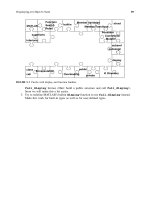
Figure 5.2 IDS 4235/4250 Back Panel
PCI Expansion Card Slots:
4250-SX :int2
4250-XL :int2, int3
4250-4FE:int2, int3, int4, int5
SCSI Interface (unused)
System Identification
Button
System Status
Indicator Connector
Keyboard
Connector
Video
Connector
Main Power
Redundant
Power (optional)
Serial Connector (com1)
Mouse Connector (unused)
Sniffing interface:int0
Command and Control
interface:int1
System Status
Indicator
(Blue and Amber)
267_cssp_ids_05.qxd 9/30/03 4:14 PM Page 188
Configuring the Appliance Sensor • Chapter 5 189
access, connect the other end of the rolled cable to one of the ports on
the terminal server.
The serial port on the computer should be configured as shown in Table 5.1.
Table 5.1 Serial Port Settings for an IDS Console
Parameter Setting
Baud Rate 9600
Data 8 bit
Parity None
Stop 1 bit
Flow Control Hardware or RTS/CTS
For the IDS-4210/4235/4250:
1. Connect the M.A.S.H. to the COM1 port on the back of the IDS
sensor.
2. Connect one end of the 180/rolled cable supplied with the IDS sensor
to the RJ-45 port of the M.A.S.H. Connect the other end either to a
port on a terminal server (as discussed earlier) or to the RJ-45 port of a
M.A.S.H. attached to a computer. If a computer is being used to provide
a serial connection to the IDS sensor, the serial port settings should be
set to the values shown in Table 5.1.
Once the serial connection to the IDS has been established, access to the IDS
“console” is now possible. For the purposes of this discussion, it will be assumed
that the IDS serial port is connected to a terminal server.
To connect to the serial port of the IDS sensor, simply Telnet to the proper port
on the terminal server, as shown in Figure 5.3.
Figure 5.3
Telnet Server Access to IDS Sensor Serial Console
###########################################################
This system is for authorized users only
All users will have their activities monitored and recorded
by the security personnel.
###########################################################
User Access Verification
Username: user-1
www.syngress.com
Continued
267_cssp_ids_05.qxd 9/30/03 4:14 PM Page 189
190 Chapter 5 • Configuring the Appliance Sensor
Figure 5.3 Telnet Server Access to IDS Sensor Serial Console
Password: ***********
Ciscoids-1
Ciscoids-1: login:
Cisco IDS Software v3
To configure Secure Shell under IDS software version 3.0 and 3.1, log in to the
sensor appliance as root. Once logged into the sensor, the sysconfig-sensor utility
can be used to configure and start up Secure Shell.
1. Log in to the sensor as root.
2. Start the sysconfig-sensor utility.A text-based menu will be displayed pro-
viding various options as shown next:
Cisco IDS Sensor Initial Configuration Utility
Select options 1 through 10 to initially configure the sensor.
1 - IP Address
2 - IP Netmask
3 - IP Host Name
4 - Default Route
5 - Network Access Control
6 - Communications Infrastructure
7 - Date/Time and Time Zone
8 - Passwords
9 - Secure Communications
10 - Display
x - Exit
Selection:
3. Select option 9 on the menu.This opens the Secure Communications
sub-menu, shown next.
Secure Communications
1 - IPSec Communications
2 - Secure Shell Communications
x - Exit
Selection:
www.syngress.com
267_cssp_ids_05.qxd 9/30/03 4:14 PM Page 190
Configuring the Appliance Sensor • Chapter 5 191
4. Select option 2 in the Secure Communications submenu to configure
Secure Shell.
Secure Shell Communications
1 - Security Level (currently LOW)
2 - Manage Secure Shell Known Hosts
3 - Host Key Operations
x - Exit
Selection:
5. Select option 1 to change the security level of the sensor. By default, the
security level is set to 3 (Low), which allows Secure Shell,Telnet, and
FTP access to the sensor.
Security Level
## The Sensor always provides Secure Shell services (including
## scp). Increase the security of the Sensor by disabling two
## services that allow clear text password authentication:
## Telnet and FTP. For maximum security disable both.
The current setting is LOW.
Select the new security level:
1 - High (Telnet and FTP disabled)
2 - Medium (Telnet disabled)
3 - Low (insecure services available)
x - Exit
Selection:
6. Select options 1, 2, or 3. It is highly recommended that the sensor’s secu-
rity level be set to 1 because of the role of the IDS sensor in the overall
network security architecture. Once the security level has been set, select
x to exit the Security Level sub-menu.
7. Select option 3 in the Secure Shell Communications menu.This displays
the Host Key Operations sub-menu.
Host Key Operations
The system has a host key with fingerprint: 1024
6c:00:fa:53:5b:16:83:24:6e:f0:f4:68:21:22:bd:7c root@CISCO_IDS
www.syngress.com
267_cssp_ids_05.qxd 9/30/03 4:14 PM Page 191
192 Chapter 5 • Configuring the Appliance Sensor
Select an option:
1 - Delete host key and generate a new one
2 - Delete host key
3 - Exit
Selection:
8. Select either 1 to delete the current host key and generate a new one, or
2 to simply delete the current host key. Changing the host key may
result in difficulty in connecting to the SSH server on the IDS sensor.
SSH clients cache the host key of the servers that they connect to. When
the client connects to an SSH server, it compares the host key of the
server to the one stored in the cache. A change in a server’s host key
may indicate a problem. Either the host key was changed by an adminis-
trator or the client is connecting to a host that may be impersonating
the server (a man-in-the-middle attack). In the case of a server host key
that was re-created by an administrator, the old host key should be
cleared out of the client’s cache so that the new key will be written in
its place.
9. Once the host key has been generated, exit out of the Secure
Communications submenus by selecting x until the main menu of the
configuration utility has been reached.
Cisco IDS Software v4.0
IDS software v4.0 and later changed the way the administrator managed the IDS
sensor. With their release, Cisco switched the underlying operating system from
Solaris 8 to Red Hat Linux 8. Additionally, IDS 4.0 provides an “IOS-like” com-
mand line interface to configure the IDS sensor appliance. Like IOS, the com-
mand line interface for the IDS 4.0 software is broken down into submenus that
the administrator must use to configure various features in the IDS sensor.
The default administrative account username/password combination for Cisco’s
IDS software 4.0 and later is: Cisco /Cisco. Cisco Systems developers realized the
weakness of this username/password combination and required that the default
password for the Cisco account be changed upon first login. Once the default
password for the Cisco account has been changed, the user is logged in and the
command line shell is started.
In order to have the proper time and date stamp placed on your log files, and
for various security certifications to work properly if they are time-based, we
www.syngress.com
267_cssp_ids_05.qxd 9/30/03 4:14 PM Page 192
Configuring the Appliance Sensor • Chapter 5 193
need to configure the sensor to have the correct time and maintain that time.
The following steps, shown in Figure 5.4, easily accomplish this:
Figure 5.4 Configuring the Sensor’s Time
sensor# clock set 20:32:00 September 27 2003
sensor# config t
sensor(config)# service host
// This is where we enter the time parameters mode
sensor(config-Host)# timeParams
// We need to adjust the offset from UTC in minutes
sensor(config-Host-tim)# offset –480
// Now we specify the standard time zone
sensor(config-Host-tim)# standardtimezone PST
// We enter the summer time parameter configuration mode
sensor(config-Host-tim)# summertimeparams
// Now we specify the summer time parameters that recur each year
sensor(config-Host-tim-sum)# active-selection recurringparams
// Enter the summertime recurring parameter mode
sensor(config-Host-tim-sum)# recurringParams
// Now specifiy the summertime timezone name
sensor(config-Host-tim-sum-rec)# summerTimeZoneName PST
sensor(config-Host-tim-sum-rec)# exit
sensor(config-Host-tim-sum)# exit
sensor(config-Host-tim)# exit
sensor(config-Host)# exit
Apply Changes:?[yes]: yes
Warning: The node must be rebooted for the changes to go into effect.
Continue with reboot? [yes]:
The next step is to configure the Secure Shell server on the IDS sensor. Figure
5.5 shows how this is done. We will use the ssh generate-key command from the
top-level prompt. Once the key has been generated, the sensor must be rebooted.
After the sensor reboots, it can be accessed directly through SSH.
www.syngress.com
267_cssp_ids_05.qxd 9/30/03 4:14 PM Page 193
194 Chapter 5 • Configuring the Appliance Sensor
Figure 5.5 SSH Key Generation and Reboot
Ciscoids-1 login: Cisco
password:
last login: Thu Sept 25 15:58:25 on ttyS0
****NOTICE***
This product contains cryptographic features and is subject to United
States and local country laws governing import, export, transfer, and use.
Delivery of Cisco cryptographic products does not imply third-party
authority to import, export, distribute or use encryption. Importers,
exporters, distributors, and users are responsible for their compliance
with U.S. laws and regulations. If you are unable to comply with U.S. and
local laws, return this product immediately.
A summary of U.S. laws governing Cisco cryptographic products may be found
at: />Ciscoids-1# ssh generate-key
MD5: 05:2D:b1:E1:06:AE:40:C5:3D:DD:01:EE:34:92:CC:20
Bubble Babble: xires-rifs-vonuz-pubue-sapet-sauron-rings-lords-fatyn-gelin-
opera
Warning: The node must be rebooted for the changes to go into effect.
Continue with reboot? [yes]:
Once the sensor has finished rebooting, the next step is to configure the
allowed hosts which can connect to the SSH server on the sensor.This can be
accomplished as follows:
1. Log in to the sensor using the cisco account.
2. Enter configuration mode using the configure terminal command at the
CLI prompt.
3. Enter the host service sub-menu using the service host command.
4. Select the network parameters sub-menu using the networkParams com-
mand.
5. Using the accessList command, enter the IP address and netmask of the
hosts or subnets that will be allowed access to the IDS sensor through
the network interface.The format of this command is: accessList
ipAddress <A.B.C.D> [netmask <A.B.C.D>].
www.syngress.com
267_cssp_ids_05.qxd 9/30/03 4:14 PM Page 194
Configuring the Appliance Sensor • Chapter 5 195
6. Once all of the IP addresses or IP address ranges have been entered into
the access-list, use the show settings command to verify them.This is
shown in Figure 5.6.
7. Exit the networkParams sub-menu and return to the host service menu.
Upon exiting the host service sub-menu, the IDS will request confirma-
tion that the changes be applied to the sensor. Press Enter to select the
default response of Yes. Otherwise, type No and press Enter .
8. Exit the host service sub-menu and the configuration menu.
Figure 5.6
Access-List Configuration on IDS Sensor
sensor(config)# service host
sensor(config-Host)# networkParam
sensor(config-Host-net)# accesslist ipaddress 10.16.17.0 netmask
255.255.255.0
sensor(config-Host-net)# show settings
networkParams
———————————————————————-
ipAddress: 10.1.9.201
netmask: 255.255.255.0 default: 255.255.255.0
defaultGateway: 10.1.9.1
hostname: sensor
TelnetOption: disabled default: disabled
accessList (min: 0, max: 512, current: 2)
———————————————————————-
ipAddress: 10.0.0.0
netmask: 255.0.0.0 default: 255.255.255.255
———————————————————————-
ipAddress: 10.16.17.0
netmask: 255.255.255.0 default: 255.255.255.255
———————————————————————-
———————————————————————-
———————————————————————-
sensor(config-Host-net)#
Once the access-lists have been configured, the IDS sensor can be accessed
using Secure Shell over the network.
www.syngress.com
267_cssp_ids_05.qxd 9/30/03 4:14 PM Page 195
196 Chapter 5 • Configuring the Appliance Sensor
The sensor needs to connect to hosts, which are SSH servers for software
upgrades, signature updates, and file copying as well as other hosts, such as Cisco
routers, PIX Firewalls, and Catalyst switches. In order to facilitate that communi-
cation, the SSH host keys of the hosts that the sensor can communicate with
must be added to the known_hosts list.The following steps can be used to add
hosts to this list:
1. Log in to the sensor using the cisco account.
2. Enter configuration mode using the configure terminal command from the
CLI prompt.
3. Use the ssh host-key command to enter the IP address of the host whose
SSH host key will be added to the known_hosts list.This is shown in
Figure 5.7.
4. When asked if the key of the host should be added to the known hosts
table, press Enter to select the default response of Yes. Otherwise, type
No and press Enter.
5. To verify the SSH keys in the known hosts list on the sensor, use the ser-
vice sshKnownHosts command at the top-level configure prompt.
6. Use the show settings command to list the hosts in the known hosts list,
as shown in Figure 5.8.
7. Exit the service sshKnownHosts sub-menu and return to the top-level
configure menu.
8. Exit configure mode.
Figure 5.7
Adding the SSH Host Key to the Known Hosts List
Ciscoids-1(config)# ssh host-key 192.168.50.14
MD5: 05:2D:b1:E1:06:AE:40:C5:3D:DD:01:EE:34:92:CC:20
Bubble Babble: xires-rifs-vonuz-pubue-sapet-sauron-rings-lords-fatyn-gelin-
opera would you like to add this to the known hosts table for this
host?[yes]
Ciscoids-1(config)#
www.syngress.com
267_cssp_ids_05.qxd 9/30/03 4:14 PM Page 196
Configuring the Appliance Sensor • Chapter 5 197
Figure 5.8 Displaying the SSH Known Hosts List
sensor# config t
sensor(config)# service ssh
sensor(config-SshKnownHosts)# show settings
rsa1Keys (min: 0, max: 500, current: 1)
id: 192.168.50.3
exponent: 35
length: 1024
modulus:
16508318659201744987257493934049916934023534822357915597860524173
8075615412030757209625612325747411882803771482511468683235829969888641604222
4132981902416287493190437220610204921172702794243732481684970354838327952077
2060730597444996382750101204023809139442273626501927211475878502549484330223
6884372899127817
sensor(config-SshKnownHosts)#
When we need to remove an entry, we use the following command:
sensor(config-SshKnownHosts)# no rsalkeys <id ip_address>
The <ip_address> parameter is the known host that we want removed from
the rsa key ring. We see in the following sample how this command works:
(config-SshKnownHosts)# no rsalKeys id 192.168.0.20
The host 192.168.0.20 is removed from the SSH known hosts list.To verify
the removal, we can use the command:
sensor(config-SshKnownHosts)# show settings
rsa1Keys (min: 0, max: 500, current: 0)
sensor(config-SshKnownHosts)#
www.syngress.com
267_cssp_ids_05.qxd 9/30/03 4:14 PM Page 197
Configuring the Appliance Sensor • Chapter 5 199
To add host keys to the sensor for use in updating the IDS software or signa-
ture packs, select the Known Host Keys link in the TOC menu at the left of
the browser window. If a host key is already in the known hosts list, it will be dis-
played in the table in the middle of the window, as shown in Figure 5.11.To add
a host key to the table, select the Add link at the bottom right of the table.
Selecting this link brings up the next page, which asks you to add the host
key of the host that the IDS will communicate with. Fill in the IP address as well
as the key modulus length, public exponent, and public modulus of the host key.
The values for the key modulus length, public exponent, and public modulus can
be obtained from the ssh_host_key.pub file. An example of such a host key is
shown in Figure 5.12. Here the public exponent is 35, the key modulus length is
1024, and the public modulus is the long number between the public exponent
value and the name identifier at the end of the host key.
Figure 5.12
The SSH Host Key Structure
1024 35 165083186592017449872574939340499169340235348223579
155978605241738075615412030757209625612325747411882803771482
511468683235829969888641604222413298190241628749319043722061
0204921172702794243732481684970354838327952077206073059744499
63827501012040238091394422736265019272114758785025494843
302236884372899127817
www.syngress.com
Figure 5.11 The Known Host Keys Table
267_cssp_ids_05.qxd 9/30/03 4:14 PM Page 199
200 Chapter 5 • Configuring the Appliance Sensor
The first number, 1024, is the Public Exponent.The second number, 35, is the
Key Modulus Length.The final set of numbers is the Public Modulus number.All of
this can be found in the /etc/ssh/ssh_host_key.pub file.This example was from Red
Hat 7.2, but most flavors of Unix/Linux will follow the same format. For a
Windows ssh client like Tera Term, you will find this information in the C:\pro-
gram files\teraterm\ssh_known_hosts file.
Using the values in the SSH host key, fill in the required fields in the Adding
Known Host Keys page, as shown in Figure 5.13. Select Apply to Sensor.The
host key is added to the known_hosts list.
The final option in configuring SSH through IDM is entering the individual
user SSH keys.This allows for public key authentication rather than using pass-
words as a means of accessing the IDS sensors.To enter the necessary informa-
tion, use a key generation tool such as ssh-keygen on Unix/Linux systems to
generate a public/private key pair for the user on the client where the private
key is going to reside.Then, display the generated public key as a set of three
numbers (Key Modulus Length, Public Exponent, Public Modulus) and enter
those numbers in the proper fields.
Compatible Secure Shell Protocol Clients
There are many SSH clients that can be used to access the IDS sensors. An SSH
client that supports the SSH-1 protocol should be used in order to access the
www.syngress.com
Figure 5.13 Adding an SSH Host Key to an IDS Sensor
267_cssp_ids_05.qxd 9/30/03 4:14 PM Page 200
Configuring the Appliance Sensor • Chapter 5 201
IDS sensor CLI.The following SSH clients have been tested by Cisco and veri-
fied to work with the SSH server in the IDS sensor software.
For Windows clients:
■
SecureCRT 3.1 is available at www.vandyke.com/products/securecrt.
■
PuTTY 0.53b is available at
www.chiark.greenend.org.uk/~sgtatham/putty.
■
The SSH Secure Shell for Workstations 3.2 is available at
www.ssh.com/support/downloads/secureshellwks.
■
Tera Term Pro 2.3 with TTSH 1.5.4 is available at
www.packetattack.com/downloads.html.
For Unix/Linux clients:
■
OpenSSH 3.4p1 is available at
www.openssh.com/pub/OpenBSD/OpenSSH/portable.
■
The SSH Secure Shell for Servers 3.2 is available at www.ssh.com/sup-
port/downloads/secureshellserver.
NOTE
While officially the preceding list represents SSH clients that are guaranteed to be
compatible with the SSH server in Cisco’s IDS sensor software, the fact is there is a
much wider range of SSH clients that are compatible.These clients include
■
OpenSSH 3.5–3.7 clients (both the portable version and the
OpenBSD version)
■
NiftyTelnet 1.1 SSH r3 (a Macintosh SSH client)
■
SSH 1.2.3
Configuring Remote Access
All IDS sensors can have their serial consoles available through a terminal server.
With IDS software v4.0 and later, this connection is easy (it’s described earlier in
this chapter). IDS sensors running IDS software 3.0 or 3.1 require a slight modi-
fication to the serial port setup on the terminal server in order for remote access
to the serial port to operate properly.The following list identifies the necessary
configuration in order to access version 3.0 and 3.1 sensors remotely.
www.syngress.com
267_cssp_ids_05.qxd 9/30/03 4:14 PM Page 201
202 Chapter 5 • Configuring the Appliance Sensor
■
Terminal Server Setup
■
BIOS setup for the IDS-4210 Sensor
■
BIOS setup for the IDS-4220 and DIS-4230 Sensors
Terminal Server Setup
The terminal server port configuration that the IDS sensor console will connect
to must be modified slightly from the default values. For the purposes of the rest
of this section, the terminal server is assumed to be a Cisco 2511-RJ router used
as a terminal server. For other terminal server hardware, consult the proper docu-
mentation.To change the configuration of the terminal server,Telnet to the ter-
minal server (or, more preferably, if the terminal server software supports SSH,
use Secure Shell) and enter configuration mode, as shown in Figure 5.13.To con-
figure the terminal port for proper operation with a version 3.0 or 3.1 sensor use
the commands displayed in Figure 5.14:
Figure 5.14
The Terminal Server Line Configuration
termsrv#config t
termsrv(config)# line <line number>
termsrv(config-line)# no exec
termsrv(config-line)# login
termsrv(config-line)# transport input all
termsrv(config-line)# stopbits 1
termsrv(config-line)# flowcontrol hardware
termsrv(config-line)# exit
termsrv(config)# exit
termsrv# wr mem
If a terminal session does not receive a proper exit signal, the terminal session
may remain open.This leaves the terminal session open and accessible without any
authentication.Typically, this occurs when the physical connection to the sensor is
disrupted (such as a line drop or disconnect).Another possible source for this
problem may be when the application connected to the terminal server is termi-
nated prematurely and the connection is dropped. In these cases, the next connec-
tion to the terminal server port will be provided access directly to the IDS sensor
console without requiring authentication. It is imperative that any session with the
www.syngress.com
267_cssp_ids_05.qxd 9/30/03 4:14 PM Page 202