sk1 001 server plus certification bible phần 4 pps
Bạn đang xem bản rút gọn của tài liệu. Xem và tải ngay bản đầy đủ của tài liệu tại đây (467.45 KB, 63 trang )
161
STUDY GUIDE
The Study Guide section provides you with the opportunity to test your knowledge
about service tools and monitoring systems. The Assessment Questions provide
practice for the test, and the Scenarios provide practice with real situations. If you
get any questions wrong, use the answers to determine the part of the chapter you
should review before continuing.
Assessment Questions
1. Which protocol is used to perform network management?
A. SNAP
B. SMTP
C. MIB
D. SNMP
2. In SNMP, what does the agent software do?
A. Collects data and sends it via e-mail to a predetermined address.
B. Collects information and forwards it to an NMS.
C. Collects data and forwards the information to a server operating system.
D. It simply collects the data, and you must manually seek the information
using a NMS.
3. What do you configure on SNMP devices to enable them to send messages to
the NMS?
A. Traps
B. Alerts
C. MIBs
D. PASS
4. What are some typical SNMP thresholds?
A. Port malfunctions
B. Network congestion
C. Packet collisions
161
Chapter 6 ✦ Study Guide
4809-3 ch06.F 5/15/01 9:47 AM Page 161
D. Device failures
E. All of the above
5. What are the two current versions of SNMP called?
A. SNMPvA and SNMPvB
B. SNMPv1 and SNMPv2
C. SNMPv4 and SMPv5
D. SNMPvC and SNMPvD
6. There are three key components in an SNMP managed network. Based on the
list below, which ones are correct?
I. Managed devices
II. Thresholds
III. Agents
IV. NMS
A. I and IV only
B. I, III, and IV only
C. I, II, and III only
D. II and III only
7. Which of the following protocol operations is used to retrieve information
from an SNMP agent?
A. Set
B. GetNext
C. Get
D. Trap
8. You decide that you are going to upgrade your third-party monitoring system
to the latest version. What conditions should be met before upgrading?
A. You have confirmed that you are upgrading to the correct version.
B. You have printed the documentation and read it thoroughly.
C. You have confirmed that the system requirements are met for the agent.
D. You have removed all the SNMP traps prior to upgrading.
162
Chapter 6 ✦ Study Guide
4809-3 ch06.F 5/15/01 9:47 AM Page 162
163
9. How do you access the Performance Monitor in Windows NT?
A. Start Menu ➪ Control Panel ➪ Performance Monitor
B. At the command prompt, type WINPERF
C. Start Menu ➪ Programs ➪ Administrative Tools
D. It is located on the desktop
10. How do you load the MONITOR utility in Novell?
A. Start ➪ Sys:
B. At the console prompt, type MONITOR.
C. At the console prompt, type START MONITOR.
D. Choose MONITOR from the Novell Console menu.
11. What is the event log utility used in Windows NT/2000 called?
A. Event Viewer
B. Log Viewer
C. EventReporter
D. System Log Viewer
12. What is the logging program in Unix that stores system and applications
events in log files called?
A.
eventlog
B. sysevt
C. syslog
D. alrtlog
13. What is the advantage of using the backup software included in the server
operating system?
A. Compatibility with the operating system environment.
B. It is cheap.
C. It has robust features.
D. The ability to back up multiple operating system environments.
14. When is the best time to take server baseline statistics?
A. When the server is behaving erratically
B. When the server is functioning normally
C. During peak loads
D. In the morning when everyone logs on to the system
163
Chapter 6 ✦ Study Guide
4809-3 ch06.F 5/15/01 9:47 AM Page 163
15. What is an import aspect to cover in the server configuration?
A. Network documentation
B. Disaster recovery documentation
C. Documenting the server configuration
D. RAID levels
Scenarios
1. You are using Windows NT server in you computer environment. Your users
are complaining of latency issues on the network. What software tool that
comes with NT could you use, and how would you use it effectively?
Answers to Chapter Questions
Chapter pre-test
1. SNMP stands for Simple Network Management Protocol.
2. The four SNMP protocol operations are: Get, GetNext, Set, and Trap.
3. Port malfunctions, network congestion, temperature out of range, packet colli-
sions, and device failures, are all possible SNMP thresholds.
4. Performance Monitor is the monitoring utility in Windows NT.
5. MONITOR is the NetWare monitoring utility.
6. Event Viewer is the Windows NT utility used to view event logs.
7. The
syslog utility is used to view system logs in Unix.
8. Windows NT Backup is the backup utility that comes with Windows NT.
9. A server baseline defines the typical activity of your network servers.
Assessment questions
1. D. SNMP, the Simple Network Management Protocol, is used to control net-
work communications devices using TCP/IP. The SNMP protocol collects
statistics from devices on the TCP/IP networks. Answer A is incorrect because
SNAP doesn’t stand for anything. Answer B is incorrect because SMTP is the
Simple Mail Transfer Protocol. Answer C is incorrect because the MIB is the
Management Information Base, which is a component of SNMP. For more infor-
mation, see the “Monitoring the network with SNMP” section.
164
Chapter 6 ✦ Study Guide
4809-3 ch06.F 5/15/01 9:47 AM Page 164
165
2. B. The agent software that is loaded by the devices collects information and
forwards the information to a Network Management System (NMS). Answer A
is incorrect because the NMS software has e-mail capabilities, not the agent.
Answer C is incorrect because the information has to go to an NMS, not the
server operating system. Answer D is incorrect because manually seeking the
information defeats the purpose of having agents on the devices. For more
information, see the “Monitoring the network with SNMP” section.
3. A. Traps are configured on SNMP devices to allow them to send alerts to the
NMS. Answers B, C, and D are all incorrect because they are not items that can
be configured to send alerts. For more information, see the “Monitoring the
network with SNMP” section.
4. E. All of these items are typical SNMP thresholds that traps can be set for. For
more information, see the “Monitoring the network with SNMP” section.
5. B. SNMPv1 and SNMPv2 are the current versions of SNMP. SNMPv3 was in the
works at the time of writing. For more information, see the “Monitoring the
network with SNMP” section.
6. B. Managed devices, agents, and the NMS are the three key components in an
SNMP managed network. Thresholds are part of the network, but are config-
ured on the managed devices. For more information, see the “Monitoring the
network with SNMP” section.
7. C. The Get operation is used by the NMS to retrieve values of the object
instances from an agent. Answer A is incorrect because the Set operation is
used to set the value of an instance. Answer B is incorrect because the
GetNext operation retrieves the value of the next instance. Answer D is incor-
rect because the Trap operation sends an event to the NMS. For more infor-
mation, see the “Monitoring the network with SNMP” section.
8. C. You should make sure that the current version of your operating system is
compatible with the latest version of the third-party monitoring system. You
may find out that it is intended for the most recent release of your server oper-
ating system, or you may be required to have a certain service pack or hot fix
installed. Answer A is incorrect because you should ensure that you are not
going to upgrade to the wrong version. Answer B is incorrect because this is
not a condition that needs to be met before installing the upgrade. This is
something that you should do prior to actually installing the original software.
Answer D is incorrect because removing all the SNMP traps will only cause you
more work as you will have to recreate them. There is no need to remove the
traps. For more information, see the “Using monitoring tools” section.
9. C. You can access to the Performance monitor by selecting Start ➪
Programs ➪ Administrative Tools, and choosing Performance Monitor from
the list. Answer A is incorrect because Performance Monitor is not located in
the control panel. Answer B is incorrect because this is a fake command. The
correct command to start Performance Monitor from the command prompt is
perfmon. Answer D is incorrect because there is no shortcut to Performance
Monitor on the desktop, unless you have created a shortcut to it. For more
information, see the “Windows Performance Monitor” section.
165
Chapter 6 ✦ Study Guide
4809-3 ch06.F 5/15/01 9:47 AM Page 165
10. B. You just need to type the word MONITOR from the console prompt to start
the Novell MONITOR utility. For more information, see the “NetWare MONI-
TOR” section.
11. A. The event log utility used for viewing the logs is called Event Viewer in
Windows NT/2000. It can be accessed by selecting Start ➪ Programs ➪
Administrative Tools. Answers B and D are incorrect because there are no
such Windows utilities. Answer C is incorrect because EventReporter is a
third-party utility. For more information, see the “Using event logs” section.
12. C. Syslog is the logging program in most versions of Unix that stores system
and applications events in log files. Answers A, B, and D aren’t real utilities.
Refer to the Event Logs section in this chapter for more information. For more
information, see the “Using event logs” section.
13. A. The only real advantage is compatibility with the operating system environ-
ment. Answer B is incorrect because some operating system vendors charge
an additional fee for including the backup software. Answer C is incorrect
because most backup programs that come with the operating system are not
as robust as third party programs. Answer D is incorrect because this is false
for most operating system backup programs. However, NetWare’s backup util-
ity has the ability to backup NT computers. For more information, see the
“Backing up the server” section.
14. B. You should always want to perform a baseline operation when the server is
performing under normal conditions. All the other answers are incorrect
because this would give you false data for your baseline. For more informa-
tion, see the “Performing a Server Baseline” section.
15. C. Ensuring you have good documentation on your server configurations will
make them easier to troubleshoot when problems occur, and easier to recover
in the event of a disaster. For more information, see the “Documenting the
Configuration” section.
Scenarios
1. Under Windows NT you would use Performance Monitor to analyze your
server environment. You could make use of the Chart mode by selecting the
proper objects and adding the appropriate counters for real time monitoring.
Some of these counters are found under the Network Segment and Network
Interface objects. They could include: % Broadcast Frames, % Multicast
Frames, % Network Utilization, Packets/sec, and Packets Sent/sec. You would
use the Log mode to do some extensive logging over the course of the day,
week, and so on. At the end of each day you could export the log files and
exam them. You would also configure the Alert mode to notify you automati-
cally if any of the thresholds that you set on the object counters were met.
You may want to set thresholds on the %Network Utilization, because this
counter should not be consistently higher than 50%.
166
Chapter 6 ✦ Study Guide
4809-3 ch06.F 5/15/01 9:47 AM Page 166
Upgrading
U
pgrading is a constant task when maintaining a network
server. You may need to add new processors to handle
the increase of new workloads, or new hard drives to increase
storage space. Upgrading memory and service tools will be
another important part of your job. The most important step
before performing any upgrade procedure is to make a full
backup of the current system and verify the backup is valid.
Some administrators have made the mistake of not verifying
the system backup, only to find out the hard way that the
backups are bad and cannot be used to restore the system.
This Part focuses on the proper procedures to follow when
upgrading a server, and how not to lose any data in the pro-
cess. More than just servers are covered in these chapters;
even uninterruptible power supplies must be upgraded even-
tually. The chapters in this Part provide you with an overall
understanding of upgrading servers and server peripherals.
Twelve percent of the exam is dedicated to upgrading, and
this Part covers each objective so you will be fully prepared.
✦✦✦✦
In This Part
Chapter 7
Upgrading
Motherboard
Components
Chapter 8
Upgrading Storage
Devices
Chapter 9
Upgrading Cards
and Peripherals
✦✦✦✦
PART
III
III
4809-3 pt03.F 5/15/01 9:47 AM Page 167
4809-3 pt03.F 5/15/01 9:47 AM Page 168
Upgrading
Motherboard
Components
EXAM OBJECTIVES
3.1 Perform full backup
• Verify backup
3.2 Add Processors
• On single processor upgrade, verify compatibility
• Verify N 1 stepping
• Verify speed and cache matching
• Perform BIOS upgrade
• Perform OS upgrade to support multiprocessors
• Perform upgrade checklist, including: locate/obtain latest test
drivers, OS updates, software, etc.; review FAQs, instruction,
facts and issues; test and pilot; schedule downtime; imple-
ment ESD best practices; confirm that upgrade has been rec-
ognized; review and baseline; document upgrade.
3.4 Increase memory
• Verify hardware and OS support for capacity increase
• Verify memory is on hardware/vendor compatibility list
• Verify memory compatibility (e.g., speed, brand, capacity, EDI,
ECC/non-ECC, SDRAM/RDRAM)
• Verify that server and OS recognize the added memory
• Perform server optimization to make use of additional RAM
3.5 Upgrade BIOS/Firmware
7
7
CHAPTER
✦✦✦✦
4809-3 ch07.F 5/15/01 9:47 AM Page 169
170
Part III ✦ Upgrading
CHAPTER PRE-TEST
1. How does memory caching affect server performance?
2. What does CPU stepping refer to?
3. What is multiprocessing?
4. What is the difference between SRAM and DRAM?
5. How does synchronous RAM differ from asynchronous RAM?
6. How does ECC memory prevent server crashes?
7. How does bus width affect I/O performance?
8. What is an AGP slot?
9. Explain the concept of bus mastering.
10. Describe hot-plug PCI.
✦ Answers to these questions can be found at the end of the chapter. ✦
4809-3 ch07.F 5/15/01 9:47 AM Page 170
171
Chapter 7 ✦ Upgrading Motherboard Components
U
pgrading hardware and software on your server is a standard job for a server
technician. As user demand begins to outgrow your server resources, you
must upgrade the components of your server as required to preserve system per-
formance. Updating the motherboard components of a server can be one of the
most complex upgrades to perform, as you are dealing with the core components of
the server. This chapter discusses upgrading motherboard components such as the
CPU, memory, and BIOS and firmware. Standard upgrading practices are also
detailed, including backing up your system, and an upgrade checklist that should
be followed when performing any type of hardware or software upgrade.
Although the “Perform upgrade checklist” objective appears several times on the
Server+ objectives, it is a general list applicable to all types of server upgrades,
and is discussed in this chapter.
Backing up Before Upgrading
3.1 Perform full backup
• Verify backup
Before you upgrade any components of your system, you must perform a full
backup of your current system. Any time an integral piece of your server is
changed, whether it is the CPU, memory, or other peripheral, there is the possibil-
ity that important data on your server could be corrupted or destroyed. You must
always be able to revert to your original configuration with little downtime.
Detailed procedures for backing up and restoring are covered in Chapter 19.
Perform a full backup of your system to tape or other media, and verify that the
backup data is there and available. Do a restore of some test files, and verify that
they are available and working after the restore. It is pointless to perform a backup
without verifying that it actually worked.
Verifying your backups is one of the most important jobs of the server technician.
It is no good just to perform a backup, because your backup software might say
that the backup was successful, but a hardware problem might cause the tapes to
be rendered useless. Do a test restore at least once a month to verify that the
backup and restore procedures are working properly.
In the
Real World
Cross-
Reference
Objective
Exam Tip
4809-3 ch07.F 5/15/01 9:47 AM Page 171
172
Part III ✦ Upgrading
Central Processing Unit
The CPU (central processing unit) is the main component of the server. It is the
brains and intelligence that controls all aspects of server operations. It processes
both program instructions and program data. It is no wonder that upgrading CPU
power in a server is one of the most common upgrades you can perform to improve
server performance. If your Network Operating System and application programs
can take advantage of more than one processor, you should definitely implement
this strategy.
For the exam, have a good grasp of the various CPU concepts, especially caching
and multiprocessing.
CPU concepts
In order to fully understand how CPU technology works, you should know a number
of terms and concepts used to describe their functionality.
Clock frequency
The clock frequency of a CPU refers to how often its internal clock “ticks.” Each tick
represents something being performed in the CPU. The faster the ticking, the faster
each instruction is being processed. The clock frequency is measured in Megahertz
(MHz).
Cache
As CPU clock speeds increased, fetching data stored in RAM began to create a per-
formance bottleneck. Therefore, a special RAM buffer, or cache, was introduced
with the advent of the Intel 80486 processor. This cache memory was built directly
onto the CPU and called Level 1 cache. Level 1 cache retains the most recently used
data, so if the CPU needs that information again, it is readily available rather than
having to seek it from the slower system RAM.
Although Level 1 cache greatly increased CPU performance, the amount of data that
can be physically stored on the CPU is limited. Therefore, a second cache layer
called Level 2 cache was created to increase performance even further. Although
Level 2 cache is larger, it is slower than level 1 cache because it is located off the
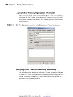
CPU between the processor and system RAM. See Figure 7-1 for the relationship
between the CPU, Level 1 cache, Level 2 cache, and RAM.
Exam Tip
4809-3 ch07.F 5/15/01 9:47 AM Page 172
173
Chapter 7 ✦ Upgrading Motherboard Components
Figure 7-1: The relationship between the CPU, Level 1 and 2 cache, and RAM
Multiprocessing
Multiprocessing simply means a system that has more than one processor. In order
for this to work, multiprocessing must be supported by both your hardware and
your software. If your operating system does not recognize other processors, it will
not use them.
There are two types of multiprocessing: symmetric and asymmetric. Because of its
higher performance and efficiency, most modern systems use Symmetric Multi-
Processing (SMP). SMP is the ability of the operating system to assign tasks to any
of the processors in the system. This enables the operating system to balance the
load of the available processors and limit the amount of unused CPU clock cycles.
In asymmetrical processing, certain processors are designated only for certain
tasks. Asymmetrical processing is not as efficient at using CPU clock cycles as sym-
metrical processing. Because specific tasks are assigned to individual CPUs, it is
quite possible that one CPU can be nearly idle while other CPUs in the server are
running at full capacity.
CPU architectures
You do not need to know the history of CPU architectures for the exam, but the fol-
lowing list of CPU family types is helpful in understanding the progression of CPU
technology.
✦ 8088: This was the first Intel chip used in PCs. It was actually less powerful
than the 16-bit 8086 chip that came out around the same time, but because of
cheaper PC boards that used 8-bit technology, the 8-bit 8088 chip was favored.
✦ 8086: This chip was very similar to the 8088 chip, but utilized a 16-bit bus for
greater data bandwidth. Its original clock speed was 4.77MHz, but a later ver-
sion was released running at 8MHz.
✦ 80286: The next processor leap was to the 80286 processor, which doubled
the speed of the earlier 8086 and 8088 processors. It could run up to clock
speeds of 20 MHz and address up to 16MB of memory. It also introduced the
CPU RAM
Level 1
Cache
Level 2
Cache
4809-3 ch07.F 5/15/01 9:47 AM Page 173
174
Part III ✦ Upgrading
concept of protected modes. Protected mode enables each application to run
in its own section of memory without interference from other programs, pre-
venting one from affecting another.
✦ 80386: The 80386 processor introduced advanced 32-bit operations. With
clock speeds of 33MHz, and later released in 40MHz versions, the 80386 again
made a giant leap in processor speed. The 386 processor was the first to use
full-protected and virtual modes, which paved the way for graphical operating
systems like Microsoft Windows A 16-bit SX version came out for lower cost
PCs, which was also popular for early portable laptop PCs.
✦ 80486: Although still running as a 32-bit processor, the 80486 processor
boasted faster clock speeds and more efficient instruction handling than its
predecessors. The 486 was the first chip to feature caching. In later versions,
internal clock doubling and tripling of the processor led to even faster speeds,
but because the processor was running faster than the memory bus, the effi-
ciency of the CPU diminished at higher levels. These unprecedented clock
speeds introduced a new problem, heat. To combat the heat problems, new
heat sink devices were introduced to aid in cooling these processors. Chip
vendors AMD and Cyrix gained in popularity at this time with the success of
their 486 chip.
✦ Pentium: Intel brought in 64-bit-level computing with the Pentium Processor
introduced in 1993. Using a superscalar design, the Pentium is capable of exe-
cuting two instructions per clock cycle. The separate caches and the
pipelined floating-point unit increase its performance beyond the x86 chips. A
floating-point unit, also known as math coprocessor, enables certain applica-
tions to perform mathematic calculations faster.
✦ Pentium Pro: The Pentium Pro was a dramatic change from the original
Pentium. The method for executing instructions changed by translating them
into smaller microinstructions and executing these on the internal CPU core.
Optimized for 32-bit code, the Pentium Pro includes an on-board Level 2 cache
that communicates with the CPU at full processor speed. It can be used in a
multiprocessor system with up to four CPU’s. (The Pentium and Pentium II
can only be used in a dual-CPU system.)
✦ Pentium II: Although the Pentium II is an advancement over the Pentium Pro,
the Pro still has some features that may make it more advantageous in a
server. The Pentium II utilizes an on-board Level 2 cache. The cache and CPU
were placed separately on a special SEC (Single Edge Contact) daughterboard
that plugs into the motherboard. Unlike the Pentium Pro, the Pentium II only
communicates with the cache at half the processor speed. However, architec-
tural changes within the chip minimize these supposed ‘downgrades’. In addi-
tion, for servers performing multimedia applications, the Pentium II added
extra MMX instructions not included on the Pentium Pro.
✦ Pentium Xeon: Available for both the Pentium II and Pentium III architectures,
the Xeon CPU acts in many ways similar to the Pentium Pro. It contains a
very large Level 2 cache that can operate at the same speed as the newer
high-clock rate CPU’s. Manufactured especially for the server and high-end
4809-3 ch07.F 5/15/01 9:47 AM Page 174
175
Chapter 7 ✦ Upgrading Motherboard Components
workstation market, the Xeon’s multiprocessor support allows for quad-CPU
systems, and even eight CPU multiprocessor systems.
✦ Pentium III: The Pentium III is considered a small upgrade from the Pentium II
processor. It does boasts higher clock speeds, 70 new MMX instructions for
3D video performance (which means little to server performance), and can
run on a 100MHz or 133MHz system bus.
✦ Pentium 4: The Pentium 4 is the latest member of the Intel Pentium family.
Boasting three times the bandwidth of the Pentium III, the Pentium 4 is a
32-bit processor using a 100MHz system bus. It currently comes in speeds of
1.4 and 1.5 GHz. It also offers the most advanced performance for demanding
video and multimedia applications.
Voltage
The voltage level of a CPU chip is an important concept that is often overlooked.
The more voltage a CPU uses, the hotter it gets. In pre-486 days, 5 volt CPUs were
the normal power rating. In order to keep heat and power consumption down in
future processors, designers began to use 3.3 volts. In the most modern CPU archi-
tectures, a dual-voltage system has been implemented. Using a voltage regulator,
the external CPU voltage is still at 3.3 volts to remain compatible with the mother-
board and other components. Internally, the CPU uses less than 3 volts, with vari-
ous manufacturers using anywhere from 2.0 volts or less to 2.9 volts.
Cooling
In the 386 and earlier CPU architectures, the concept of CPU cooling was not that
important, but as the clock speeds of the CPU began to double and quadruple with
the 486 family of processors, the need for a cooling mechanism was mandatory. If a
CPU chip begins to overheat, it starts to malfunction, and this can result in strange
and irregular behavior, including freezes, reboots, and application errors. CPU mak-
ers began to include heat sinks and fans on their CPU’s to keep them cool. A heat
sink is simply a piece of metal, usually aluminum, that is placed on top of the CPU
to increase the surface area of the chip and enable heat to dissipate in greater
amount through protruding fins projecting out from the top of the heat sink. In all
modern processors, and fan is built into the heat sink to increase cooling.
Types of CPU sockets
The type of socket or slot that the CPU plugs into on the motherboard has changed
dramatically over the years. The technician must be careful in verifying the proper
socket type of CPU before an upgrade. The following is a list of the most common
types of CPU sockets and slots.
✦ Socket 1: This socket is found on 486 motherboards and supports 486 chips. It
contains 169 pins and operates at 5 volts.
✦ Socket 2: The next socket from Intel was a minor upgrade from the Socket 1. It
has 238 pins and is 5 volt. It supports all the Socket 1 chips and adds support
for the Pentium OverDrive.
4809-3 ch07.F 5/15/01 9:47 AM Page 175
176
Part III ✦ Upgrading
✦ Socket 3: The next Intel socket contains 237 pins and operates at 5 volts, but
can also operate at 3.3 volts. This can be switched using a jumper setting on
the motherboard. It is backward-compatible with Socket 2 processors.
✦ Socket 4: This type of Intel socket was introduced with the Pentium class of
machines. The socket has 273 pins, and operates at 5 volts. It supports only
the low-end Pentium 60MHz-66MHz and the Overdrive because these chips
are the only Pentiums operating at 5 volts.
✦ Socket 5: This socket supports the later Pentium machines from 75 MHz to
133 MHz. It has 320 pins and operates at 3.3 volts. Socket 5 has been replaced
by the Socket 7.
✦ Socket 6: A little-used socket architecture that was made for late 486 models,
but with the introduction of the Pentium, was quickly made obsolete.
✦ Socket 7: This is the most widely used socket. It contains 321 pins and oper-
ates in the 2.5 to 3.3 volt range. It supports most modern Pentium-class, AMD,
and Cyrix chips. This type of socket introduced the voltage regulator that
makes internal voltages lower than the external 3.3 volt motherboard standard.
✦ Socket 8: A socket used for Pentium Pro CPUs, it contains 387 pins and operates
at 3.1 to 3.3 volts. It is very large compared to other socket types because the
Pentium Pro’s onboard Level 2 cache made the chip much larger than others.
✦ Slot 1: With the introduction of this new type of slot, Intel moved the CPU
socket onto a daughtercard that plugs into the motherboard. This provides
faster communication between the processor and Level 2 cache, as the cache
module itself was installed on the daughterboard. The CPU can communicate
with the cache at half its clock speed. The CPU slot has 242 pins and operates
at 2.8 to 3.3 volts.
✦ Slot 2: A slot design that was introduced with newer Pentium III chips. The
Slot 2 features a wider pin connector than the Slot 1, using 330 pins. In con-
trast to the Slot 1, the CPU can communicate with the on-board L2 cache at its
full clock speed.
✦ Slot A: This is a new proprietary slot design AMD is using with the their new
Athlon processor. Although similar to Intel’s Slot 1, Slot A uses a new bus pro-
tocol that increases communication speeds between the CPU and RAM to
over 200MHz.
Installing a CPU
3.2 Add Processors
• On single processor upgrade, verify compatibility
• Verify N 1 stepping
• Verify speed and cache matching
• Perform BIOS upgrade
• Perform OS upgrade to support multiprocessors
Objective
4809-3 ch07.F 5/15/01 9:47 AM Page 176
177
Chapter 7 ✦ Upgrading Motherboard Components
For most modern servers, there are two types of upgrades for the CPU: chip-for-
chip upgrade, and daughtercard upgrade. Another method of upgrading a CPU,
which is now obsolete and outdated, is the piggyback method, where an overdrive
CPU is installed on top of an already-installed processor.
Chip-for-chip upgrade
When performing this type of upgrade, you are simply replacing the old CPU with a
new one. Most modern boards have a zero-insertion force (ZIF) socket or a Slot 1
socket, where the chip can be easily removed. A ZIF socket has a small lever arm
that holds the chip in place when closed. When the lever is raised, the chip pops
out for easy removal. Older, low-insertion force (LIF) sockets required the chip to
be forced into its socket by hand, increasing the danger of damaging the pins when
inserting or removing the chip.
Daughterboard upgrade
A daughterboard upgrade involves installing a new chip on a card that is already
plugged into your motherboard. The daughtercard looks very similar to a regular
computer expansion card, with a single-edge connector that plugs into special
motherboard slot.
Processor upgrade procedures
To upgrade a processor, there are some things you need to verify first. Follow these
steps:
Upgrading a processor
1. Verify compatibility. Be sure to examine your current CPU and motherboard
settings for proper bus speed and architecture, slot size, and proper cooling
mechanisms.
2. Verify stepping and OS compatibility for multiprocessing. If you are going to
install another processor in a multiprocessing system, you must verify that
the OS will support such a configuration. Also, carefully check the stepping
number of your CPU by physically examining the identifying information on
the chip. Stepping refers to a revision of a CPU chip, usually to correct a small
error in previous version. In a multiprocessing system, the stepping value of
the new CPU must be identical to the one already installed to work properly.
3. Verify the BIOS. You will have to verify that your current BIOS version sup-
ports the CPU that you are about to upgrade., The BIOS will often report an
older CPU version after a CPU upgrade, because its internal software does not
recognize the new CPU.
4. Verify the slot or socket. Examine your current CPU for the type of socket
or slot it uses. Your upgrade CPU must have the same number of pins to fit
properly.
4809-3 ch07.F 5/15/01 9:47 AM Page 177
178
Part III ✦ Upgrading
5. Remove the old chip. If there is a fan on top of the old chip, remove it first, but
do not disconnect it from the rest of the system, because you will to need to
put it back onto your new chip if it does not have its own cooling mechanism.
If the chip is in an older LIF socket, you will need to use a chip puller tool to
gently pry the CPU out of the socket. If your system uses a ZIF socket, simply
raise the lever arm and the chip should pop right out of the socket.
6. Install the new CPU. For a LIF socket, use caution, as you did when removing
the old chip. Line up the pins properly before slowly pushing the CPU down
tightly into the socket. For a ZIF socket, align the CPU as before, and then
bring down the lever arm to lock the CPU chip in place.
For a Slot 1 processor, you must align the chip correctly over the slot. The
chip will only go in one way. Press the CPU into the slot until the clips con-
nect, securing the CPU into the slot.
7. Reboot the server. You can now reboot the server, but you must pay special
attention to any error messages you get on the boot screen. Make sure your
BIOS reports the name of the new CPU correctly.
For the exam, remember that for multiprocessor systems, the CPU’s should be
identical, including the stepping revision number. Also ensure that the OS is
updated to support multiprocessing.
System Memory
RAM (Random Access Memory) is the system memory where the server stores run-
ning applications and data. Server memory is crucial to server performance, as no
amount of CPU power will help a server without enough memory to store its opera-
tions. Upgrading the memory of a server is a very common procedure for server
technicians. Typically, when new applications are added, they demand more mem-
ory from the server. Upgrading memory is just as integral a part of server mainte-
nance as CPU and disk upgrades. There are many different types of memory
available, and it is very easy to make a mistake in choosing the RAM for your partic-
ular server. The memory types, size, packaging, and supported chip sets are all
things you should keep in mind when upgrading server memory.
Basic types of server memory
Your server contains many different types of memory. Some forms of memory are
based right on the motherboard, to store static information related to the systems,
and other types of memory are dynamic, such as system RAM, which is used to
temporarily store information during processing. A detailed knowledge of each type
of memory and its purpose, is invaluable when trying to improve the performance
of your system.
Exam Tip
4809-3 ch07.F 5/15/01 9:47 AM Page 178
179
Chapter 7 ✦ Upgrading Motherboard Components
ROM
Read Only Memory (ROM) is a type of memory that cannot be written to; its infor-
mation is static. When power is disconnected from your machine, and then recon-
nected, the information stored in ROM will still be there. ROM is most commonly
used in system BIOS chips, as they store information about the computer that does
not change. When you first turn on a computer, it reads its system information
stored in ROM to be able to boot properly. Most modern computers contain a vari-
ant of ROM called EEPROM (Electrically Erasable Programmable ROM), which
enables you to make changes to the ROM through special software. Using a flash
BIOS, the computer’s system information can be updated to recognize new hard-
ware and features.
RAM
Random Access Memory (RAM) can be both read and written. This memory is one
of the most important contributing factors to the performance of your server. With
too little RAM, your server will not be able to run as many applications, large-scale
programs may work very poorly, and potential server crashes are likely. RAM is
volatile, and when the server is switched off, anything that was in memory will be
lost. There are two main types of RAM: SRAM and DRAM.
SRAM
Static RAM continues to hold on to its data without a refresh, as opposed to DRAM
(Dynamic RAM), which must be refreshed constantly to retain its information.
SRAM is much faster, but more expensive than DRAM, and is typically used for
cache memory.
DRAM
Dynamic RAM is constantly refreshed every few milliseconds, hence its dynamic
nature. It is used for main system memory because it is much less expensive than
SRAM, and the memory modules can fit into a smaller area.
There are several different types of DRAM:
✦ FPM: Fast Page Mode RAM was the traditional RAM used in PC’s for many
years. It came in modules of 2MB to 32MB of RAM. It is considered too slow
for fast, modern system memory buses.
✦ EDO: Extended Data Out DRAM is slightly faster than FPM RAM. It is similar to
FPM RAM, but the timing mechanisms have been changed so that no single
access to the memory can begin before the last one has finished. It is, there-
fore, slightly faster than FPM memory, but still too slow for modern high-
speed memory bus requirements.
✦ ECC: Error-Correcting Code memory includes special parity operations for
testing the accuracy of data as it passes in and out of memory. ECC RAM is
used mostly in servers that require high availability. ECC RAM can prevent
server crashes caused by memory errors. ECC RAM is slower than other
types of RAM because of the overhead involved in calculating parity.
4809-3 ch07.F 5/15/01 9:47 AM Page 179
180
Part III ✦ Upgrading
✦ SDRAM: Synchronous DRAM differs from earlier types of RAM in that it
does not run asynchronously with the system clock. SDRAM is specifically
designed to synchronize with the system clock speed of the computer. SDRAM
is the most common form of RAM in modern servers, because of its ability to
scale to the faster bus speeds of new motherboards.
Another technique that sets SDRAM apart from other memory types is mem-
ory interleaving. Interleaving is used by high-end motherboards to increase
performance. Memory interleaving allows simultaneous access to more than
one area of memory. This improves performance because it can access more
data in the same amount of time. This type of memory is helpful with large
enterprise database and application servers.
✦ Rambus (RDRAM): Rambus Direct RAM is a new revolutionary RAM type cre-
ated by a company named Rambus, partnered with Intel. It contains an intelli-
gent micro-channel memory bus, which can run at a very high clock speed.
Although the memory module itself is only 16-bit wide compared to the tradi-
tional 64-bit SDRAM module, this allows a much higher clock frequency.
Adding more memory channels increases the throughput to even greater
levels.
Memory packaging types
Memory can come in a wide variety of different packaging, and has been manufac-
tured with a variety of different numbers of pins. It is very important that you verify
the type of memory packaging required by your motherboard before purchasing
upgrade memory.
SIMM
Single Inline Memory Modules (SIMM) are the older standard of memory modules.
They come in two types, an older 8-bit 30-pin version, and a newer 32-bit 72-pin ver-
sion. These chips are connected into sockets on the motherboard, which contain
clips to keep them in place.
DIMM
Dual Inline Memory Modules (DIMM), used in most modern computer systems,
are 64-bit modules and have 168 pins. The term dual is used to denote that these
modules have two 32-bit paths for a full 64-bits, whereas a SIMM uses a single
32-bit path. They will not work in older motherboard SIMM sockets because of
the difference in size. They are the most common form of packaging for SDRAM
types of memory. There are three DIMM types: buffered, registered, and unbuffered.
Most memory modules are unbuffered. Buffered modules contain a buffer to isolates
the memory from the controller to minimize the load that it sees. Registered
modules, used in newer Fast RAM modules, contain a register that delays all infor-
mation transferred to the module by one clock cycle.
4809-3 ch07.F 5/15/01 9:47 AM Page 180
181
Chapter 7 ✦ Upgrading Motherboard Components
Fast RAM
To keep up with the modern fast processors, RAM manufacturers have also had to
come up with a RAM solution that can keep up with CPU performance. The follow-
ing are some of the more advanced types of RAM available today:
✦ PC100, PC133: The new Intel chipsets have a 100MHz or 133MHz memory
bus. To match these faster bus speeds, you must use PC100 or PC133 memory
modules. They use 168-pin DIMM packaging.
✦ SPD: Serial Presence Detect (SPD) is a small EEPROM that resides on newer
fast RAM DIMMS. When a computer system boots up, it detects the configura-
tion of the memory modules in order to run properly.
✦ RIMM (Rambus): RDRAM memory modules are called Rambus Inline Memory
Modules (RIMM) and contain 184 pins. Since RDRAM works in channels, any
empty sockets have to be filled with a blank memory module called a
Continuity Rambus Inline Memory Module (CRIMM).
Installing memory
3.4 Increase memory
• Verify hardware and OS support for capacity increase
• Verify memory is on hardware/vendor compatibility list
• Verify memory compatibility (e.g., speed, brand, capacity, EDI, ECC/non-ECC,
SDRAM/RDRAM)
• Verify that server and OS recognize the added memory
• Perform server optimization to make use of additional RAM
Follow these steps to correctly install new memory:
Upgrading memory
1. Verify compatibility. As with CPUs, there are many different types of memory
and memory sockets, and finding the right memory for your server will usu-
ally take some investigation to ensure compatibility.
2. Verify the memory with the manufacturer and motherboard manual.
Initially, you should confirm with your vendor or the manufacturer of your
system the type of RAM that the server uses. Consult the manual for your
motherboard to see what type of memory it can handle. You will need to
check for memory size, speed, type, and capacity.
Objective
4809-3 ch07.F 5/15/01 9:47 AM Page 181
182
Part III ✦ Upgrading
3. Check the memory banks and slots. Older servers might be using SIMM tech-
nology. The SIMM memory slots are organized in banks, and each bank must
be full for the system to work properly. The memory must be installed in
equal pairs if a bank contains more than one slot. You cannot put 32MB in one
slot and leave the other one empty; you must use two 16MB SIMMs. The mem-
ory chip is usually inserted into the SIMM slot at a 45-degree angle, and then
snapped vertically into place with the clips on the slot’s edges.
Newer DIMM slots are separated into single-slot banks, so there is no need to
install memory chips by pairs. There are typically three slots labeled DIMM 0,
DIMM 1, and DIMM 2. Start with the lower number slot when adding or replac-
ing RAM chips. In a DIMM slot, the memory is inserted vertically, directly into
the slot, and secured by two levers on either side of the slot.
4. Verify the Upgrade. When you are finished with the memory upgrade, power
up the server, and note any error messages that come up during the booting
stage. Verify that the amount of RAM listed by the BIOS matches the memory
that you have installed. Any discrepancies could mean that one of your mem-
ory chips may not be properly seated, or it could be defective.
When running your OS and any applications, be wary of any signs of errors
relating to memory. You may have to reconfigure your applications to benefit
properly from the added RAM.
For the exam, most hardware-based RAM questions deal with the type and avail-
ability of slots in the motherboard, and compatibility issues.
System Bus Architectures
The communications bus of your server is the all-important link between its vari-
ous components. The processor, memory, expansion cards, and storage devices
talk to each other through one or more system buses.
Although system bus architectures are not emphasized on the exam, you should
know the various architectures, and know the capabilities of the most recent
buses such as PCI and AGP.
A bus is a channel through which information flows between devices in your sys-
tem. A device is able to plug or tap into a system bus, and relay specific information
to the other devices on the same bus. The bus itself is simply a common set of
wires that connect all the computer devices and chips together. When upgrading
any devices on your system board, it is important to know what type of system bus
you are running, especially its bus-width, clock speed, and throughput.
Exam Tip
Exam Tip
4809-3 ch07.F 5/15/01 9:47 AM Page 182
183
Chapter 7 ✦ Upgrading Motherboard Components
In most server architectures there are two main buses that are tightly integrated:
the system bus, which facilitates communication between the CPU and memory, and
the I/O bus, which connects the CPU with other devices in the system. The buses
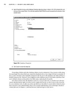
are connected by a bridge, which is part of the motherboard chipset. Figure 7-2
shows the relationship between these buses and your system components.
Figure 7-2: Basic system and I/O bus diagram
System bus concepts
The system bus has three main characteristics that define its performance and
data-handling capabilities:
✦ Bus speed: The speed of the bus reflects how many bits of information can be
sent through system. Most buses transmit one bit of data per clock cycle.
✦ Bus width: The wider the bus, the more information can flow through it. Older
bus widths were 8 and 16-bit, while modern buses use a 64-bit width.
✦ Bus bandwidth: Bandwidth refers to the total amount of data that can be
transferred on a bus over a certain amount of time. This is typically measured
in Megabits per second (Mbps).
Devices:
Storage
Peripheral Cards
Adapters
Keyboard/Mouse
CPU
SYSTEM BUS
I/O BUSESBRIDGE
RAM
CACHE
4809-3 ch07.F 5/15/01 9:47 AM Page 183
184
Part III ✦ Upgrading
The system bus is designed to match a particular CPU. In older computer architec-
tures, the system bus speed closely followed the CPU speed. Bus widths, which
determine how much data can travel over the bus, were typically 8- and 16-bit data
channels.
In the late 486 and early Pentium models, technology advances enable the CPU
internal speed to double its clock frequency, while the system bus retained is own
internal clock speed at half the speed. Bus widths were now running at 32-bit.
For many years, the 64-bit Pentium architecture generally relied on 66MHz bus
speeds. Recently, in AMD and Pentium III machines, system buses now run either
100MHz or 133 MHz. The new Pentium 4 CPU runs on a 400 MHz system bus.
Table 7-1 summarizes the relationship between the different processors and the
buses.
Table 7-1
Bus and Processor Speeds
CPU Bus Width Bus Speed (MHz)
8088 8-bit 4.77
8086 16-bit 8
80286 16-bit 12
80386 16-bit 16
80486SX-25 32-bit 25
80486DX-33 32-bit 33
80486DX2-50 32-bit 25
80486DX-50 32-bit 50
80486DX2-66 32-bit 33
80486DX4-100 32-bit 40
5X86-133 32-bit 33
Intel Pentium 60 64-bit 60
Intel Pentium 100 64-bit 66
Cyrix 6X86 P133+ 64-bit 55
Intel Pentium 166 64-bit 66
Intel Pentium II 64-bit 66
Intel Pentium III 64-bit 100, 133
Pentium 4 64-bit 100×4
4809-3 ch07.F 5/15/01 9:47 AM Page 184
185
Chapter 7 ✦ Upgrading Motherboard Components
I/O buses
As the system bus connects the CPU to RAM, I/O buses connect the CPU to all other
components. The I/O buses differ from the system bus in speed. I/O speeds are
lower than system bus speeds, as most devices only operate at lower clock speeds.
The following are the types of I/O buses.
Legacy I/O buses
The Industry Standard Architecture (ISA) bus is the most common of all bus types,
and even though its technology is quite old, a 16-bit architecture going back to the
early 1980’s, most modern PCs and servers still come with a few ISA slots on the
motherboard. Older 8-bit and 16-bit peripheral cards still abound today, which typi-
cally are serial or modem cards.
The Micro Channel Architecture (MCA) bus was created in 1987 by IBM as a rival to
the ISA bus. It boasted 32-bit bus width, a bus mastering system for greater bus effi-
ciency, and a plug-and-play system that predated modern plug-and-play technology
by many years. Unfortunately, even though MCA was far superior to ISA technology,
it was proprietary to IBM, and was not compatible with ISA. These factors led to the
discontinuation of MCA.
The Extended Industry Standard Architecture (EISA) bus was created as an extension
to the ISA standard, although it never became very popular in the PC and server
world. EISA was created by other vendors to take the strengths of MCA bus archi-
tecture, and make it compatible with ISA. Like MCA, it also featured a 32-bit bus
width, plug and play capabilities, and bus mastering. EISA, much like the MCA bus,
did not catch on, and was quickly eclipsed by newer, faster bus technologies like
VESA local bus, and PCI.
Local bus technologies
As CPU speed began to increase exponentially, a bottleneck developed at the sys-
tem bus level. The most notable application to be affected by this performance
issue was graphical display systems. The amount of information to be conveyed to
video card was too great for the slow ISA bus to handle. To increase graphics per-
formance, the idea of a local bus, a bus that was more closely integrated with the
processor and memory bus, came into being.
The first local bus technology to become popular was Video Electronics Standard
Association (VESA) local bus. The VESA local bus was introduced in 1992; the prod-
uct of a standards group dedicated to increasing video performance on personal
computers. Running as a 32-bit 33MHz bus, VESA was a direct extension of the 486
processor/memory bus. It did not, however, support bus mastering or plug-and-
play. It also did not have much relevance with the server market, which did not
need advanced video capabilities. Although popular during the 486 era, it was
quickly rendered obsolete by the Pentium computer and its PCI local bus.
4809-3 ch07.F 5/15/01 9:47 AM Page 185