the best damn firewall book period phần 4 pot
Bạn đang xem bản rút gọn của tài liệu. Xem và tải ngay bản đầy đủ của tài liệu tại đây (2.23 MB, 133 trang )
Advanced PIX Configurations • Chapter 10 365
Summary
The Cisco PIX firewall is an advanced product and has many different options for supporting
various application-layer protocols as well as protecting against network-layer attacks. It also sup-
ports content filtering for outbound Web access, intrusion detection, various routing options such
as RIP and stub multicast routing, and DHCP server and client functionality.
Many protocols embed extra IP address information inside the exchanged packets or nego-
tiate additional connections on nonfixed ports in order to function properly.These functions are
handled by the PIX application inspection feature (also known as fixup). PIX supports FTP
clients and servers in active and passive modes, DNS, RSH, RPC, SQL*Net, and LDAP proto-
cols. It also supports various streaming protocols such as Real-Time Streaming Protocol,
NetShow, and VDO Live.Another set of supported protocols includes all H.323, SCCP, and
SIP—all used in VoIP applications.The PIX monitors passing packets for the embedded informa-
tion and updates its tables or permits embryonic connections according to this information. It is
also able to NAT these embedded addresses in several cases.
Content filtering features on the PIX can be used to enforce a company’s acceptable use
policy.The PIX can interface with Websense (www.websense.com) or N2H2 (www.n2h2.com)
servers and deny or allow internal clients to access specific Web sites.The PIX is also able to filter
out Java applets and ActiveX code from incoming Web pages to protect clients against malicious
code.
For SOHO environments, the PIX firewall provides DHCP server and client functionality,
although server capabilities are rather limited. DHCP server supports a couple of specific options
that are used by Cisco IP Phones. Other useful PIX features include support of stub multicast
routing and PPP over Ethernet client capabilities. It also supports RIPv1 and v2, including
authentication and multicast updates for v2.
Finally, the PIX has embedded protection against various DoS attacks, such as SYN floods,
attacks on AAA mechanisms, and excessive fragmentation. Antispoofing is supported by the
reverse-path forwarding feature.
www.syngress.com
252_BDFW_ch10.qxd 9/18/03 4:55 PM Page 365
252_BDFW_ch10.qxd 9/18/03 4:55 PM Page 366
Troubleshooting
and Performance
Monitoring
Best Damn Topics in This Chapter:
■ Troubleshooting Hardware and Cabling
■ Troubleshooting Connectivity
■ Troubleshooting IPsec
■ Capturing Traffic
■ Monitoring and Troubleshooting
Performance
Chapter 11
367
252_BDFW_ch11.qxd 9/18/03 4:56 PM Page 367
368 Part III • PIX Firewalls
Introduction
This chapter focuses on troubleshooting PIX firewalls. Once you have mastered its command
syntax and basic firewall operations, the PIX is a relatively simple device to configure. Its library
of commands is small compared to that of Cisco routers and switches. In previous chapters, we
covered the PIX firewall in detail, from the various models in the product line to simple and
advanced configurations.This book contains information on how to integrate the PIX firewall
into your existing network. As good as your PIX configuration is, problems will still crop up, and
you need to know how to resolve them.The purpose of this chapter is to present a methodology
that you can use to attack these problems and avoid missing critical troubleshooting steps.
Hardware and cabling problems can be a bane to an otherwise well-functioning network. A
hardware problem becomes apparent if you know which indicators to monitor.The limited
number of cable types that the PIX supports eases our cable troubleshooting considerably.This
chapter provides technical information about these cables so you can validate them.
The PIX firewall is an IP device. Granted, it is a highly specialized device that performs vital
security functions, but it is still an IP device. As such, it needs to know where to send traffic. We
highlight some common connectivity problems and how you can address them. A valuable func-
tion of the PIX firewall is its ability to conserve IP address space and hide network details via
Network Address Translation (NAT). If you have problems with NAT, you must be able to isolate
and eliminate them.
The PIX firewall provides several access control mechanisms, from simple access lists to com-
plex conduit statements.These access mechanisms have simultaneous loose/tight properties in that
certain traffic is allowed while other traffic is denied.Your troubleshooting will not only seek to
resolve access problems, but also find the right balance between permitting and denying traffic.
Entire books have been written on IPsec, and for good reason. IPsec can protect your traffic
from end to end without having to be implemented at every hop along the way. IPsec configura-
tion can be complex.You must be intimately familiar with IPsec operations in order to support
and troubleshoot it.This chapter covers several key aspects of IKE and IPsec to aid your moni-
toring and support.
Capturing network packets on the PIX firewall can enable you to troubleshoot more effec-
tively.The PIX firewall offers several features that you can use to capture traffic for analysis and
problem isolation. Available tools include native PIX commands as well as third-party tools for
network capture and packet decode.
How do you know if your PIX firewall is performing as well as it should? How would you
know if it was overloaded? You need to monitor firewall performance and health proactively.The
goal of monitoring is to prevent minor glitches from turning into major problems.The output of
your monitoring efforts can be quite dense and arcane, so you need to know how to interpret
what you are monitoring.
Troubleshooting Hardware and Cabling
The most important thing to remember in troubleshooting is to tackle your problems logically so
you don’t miss any important components or steps.You must confirm the health of all the com-
www.syngress.com
252_BDFW_ch11.qxd 9/18/03 4:56 PM Page 368
Troubleshooting and Performance Monitoring • Chapter 11 369
ponents that make up the firewall. When addressing PIX firewall problems, you would be best
served using the OSI model to guide your efforts.This model was created to guide development
efforts in networking by dividing functions and services into individual layers. Per the OSI
model, peer layers communicate with each other. For example, the network layer at one host
communicates with the network layer at another host.
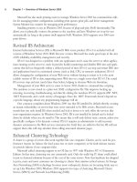
The approach advocated in this chapter is based on the OSI model shown in Figure 11.1.
Problems are tackled starting at the lowest layer, such as validating hardware and cabling at the
physical layer. Only when the components at the lower layer have been validated do you turn
your attention to components at a higher layer.
This chapter organizes troubleshooting efforts by the OSI model. Initial troubleshooting starts
at Layer 1, the physical layer. Once all physical components have been validated, the trou-
bleshooting focus is shifted to the data link layer components, and so on, up the OSI stack.This
controlled approach ensures that we do not miss any facet of our security configuration where
the problem could be.
Our first steps in troubleshooting start with physical layer issues. In the context of the PIX
firewall, physical components include the firewall hardware and cabling. We start our discussion
with a quick overview of the PIX firewall hardware architecture and cabling.
www.syngress.com
Figure 11.1 The OSI Model
Provides the user/application
an interface into the network.
Converts and restores data in a
format that can be transported
between network devices.
Example protocols include
ASCII or EBCDIC.
Manages and synchronizes the
sessions between devices.
Segments and reassembles data
for the Session and Network l
ayers. Establishes connections
and provides flow control.
Addresses and routes data on
a network. IP and IPX are
examples of network protocols.
OSPF, EIGRP, and other routing
protocols operate at this layer.
Assembles raw data into
acceptable formats for the
Physical and the Network layers.
802.3 and HDLC are example
protocols.
Addresses details of
connecting to physical
media such as 10BaseT cable.
Application
Presentation
Session
Transport
Network
Data Link
Physical
7
6
5
4
3
2
1
Access List
Conduit
NAT/PAT/Static
Global
IPsec/VPN
Routing
Hardware
Cabling
252_BDFW_ch11.qxd 9/18/03 4:57 PM Page 369
370 Part III • PIX Firewalls
Troubleshooting PIX Hardware
Knowing the details of each PIX firewall model can be helpful in validating your configuration
and troubleshooting. Such knowledge can quicken your problem-solving process from the onset
by enabling you to determine how to interpret the symptoms you are witnessing. If you use the
wrong firewall model for the wrong function, no amount of troubleshooting is going to make it
work.
It can be said that your troubleshooting actually starts with your network design and security
planning.There are several models of the PIX firewall, each capable of supporting certain num-
bers and types of network interfaces. Each model has its own upper limit on the number of max-
imum simultaneous connections, as shown in Figure 11.1.Therefore in Table 11.1 we provide
only a snapshot of each model.
Table 11.1 PIX Firewall Model Features and Capabilities
Interface Types Maximum Number
Model Supported of Interfaces Failover Support
501 Ethernet Four-port 10/100 switch No
Fast Ethernet
Fixed 10BaseT
506E Ethernet Two fixed 10/100 Ethernet No
Fast Ethernet
515E Ethernet Two fixed 10/100 Ethernet Yes
Fast Ethernet Two expansion slots
Maximum: Six ports
525 Ethernet Two fixed 10/100 Ethernet Yes
Fast Ethernet Four interface slots
Gigabit Ethernet Maximum: Eight ports
535 Ethernet Nine interface slots Yes
Fast Ethernet Maximum: 10 ports
Gigabit Ethernet
The Firewall Services Module (FWSM) 1.1 for the Catalyst 6500 series switches provides no
physical interfaces. Instead, it provides support for up to 100 VLAN interfaces. For failover sup-
port, the FWSM has a dedicated logical interface.
It is important to know whether the PIX firewall you are using is adequate for the demands
planned for it. For example, if you have a network on which 100,000 simultaneous connections
will be requested through the firewall and you are using a PIX 501, the firewall will immediately
become congested and be virtually unusable. In this scenario, no amount of troubleshooting and
configuration will enable the PIX 501 to support the load.The capacity of each firewall model is
important because it determines the load that can be placed on that firewall. Overloading your
firewall is an invitation to crashes or congestion. Underloading a PIX firewall, although great for
performance, can be wasteful in terms of unused capacity and monetary return on investment.
For example, if you have a network on which there will never be more than 200 simultaneous
www.syngress.com
252_BDFW_ch11.qxd 9/18/03 4:57 PM Page 370
Troubleshooting and Performance Monitoring • Chapter 11 371
connections, installing a PIX 535 means that you will not recoup your hardware or software
investment, although performance will be fantastic.
The different models support different types of interfaces and in specific quantities, as shown
in Table 11.1. Not shown in the table is the fact that Token Ring and FDDI are also supported
by several of the models. Cisco ceased PIX firewall support for Token Ring and FDDI networks,
starting with PIX software v5.3. As a rule of thumb, do not mix and match interfaces: Configure
the PIX firewall as all Token Ring, all Ethernet, or all FDDI. Maintaining such network purity
reduces the burden on the PIX firewall since it will not have to translate between the different
LAN formats. Only models 515 and up support interfaces other than Ethernet.
The PIX firewall has a system for identifying its network interfaces, which you need to
understand in order to troubleshoot the right piece of hardware. Not knowing how interfaces are
enumerated and identified can consume valuable time that could otherwise be used for trou-
bleshooting. Figure 11.2 shows how to “read” the network interface identification scheme.
Interface card numbering starts with 0 at the right, with card slot numbers increasing as you go
left.The slot in which the card is installed determines the number that is given to that card. Ports
are numbered top to bottom, starting with 0 for the port at the top of the card.
For example, the topmost port on an Ethernet interface card installed in Slot 3 would be
identified as Ethernet 3/0. Fixed interfaces are first numerically starting on the right at 0, then
the next fixed interface to the left is 1.The first installed network interface card would be 2 (as in
www.syngress.com
Figure 11.2 PIX Firewall Interface Numbering
PIX Models 515
and above.
Slot determines the number, with lowest port
number at left and increasing to the right.
Ports are numbered from top, left to right,
starting lowest at the topmost left.
Fixed interfaces are numbered first.
Fixed
1
PIX Models 506
and below.
Fixed port configuration only!
Ports are numbered low to high,
right to left.
3254
7698
Fixed
0
Fixed
4
Fixed
3
Fixed
2
Fixed
1
Fixed
0
252_BDFW_ch11.qxd 9/18/03 4:57 PM Page 371
372 Part III • PIX Firewalls
Slot 2) and its topmost interface is 0. It is important that you learn this scheme not only to iden-
tify the specific cards but to also ensure that your configuration and troubleshooting efforts focus
on the correct interface.
The memory architecture of the PIX firewall is somewhat similar to that of Cisco routers
with the exception that there is no NVRAM memory.The PIX uses flash memory to store the
firewall operating system (image) as well as the configuration file. Main memory is used to handle
data being processed. As a rule of thumb, the flash memory should be big enough to hold the
software image and the configuration. Of all the memory types, main memory can potentially
have the most significant impact on performance since it is the working space of the firewall.
Main memory is used to store data that is waiting to be processed or forwarded.You can never
have too much, and you will definitely notice when you have too little, because packet loss will
increase or IPsec traffic will become lossy or laggardly.
Each firewall has visual indicators of operation in the form of light-emitting diodes (LEDs).
These LEDs vary by model, but some are common to all. Figure 11.3 shows several PIX firewall
LEDs and their meanings. Nurturing your knowledge of these LEDs will enable you to start your
Layer 1 troubleshooting from the outside.
Study the information in Figure 11.3.The LEDs can be lit, unlit, or flashing, all of which
indicate specific conditions.The ACT LED, since it can appear on both the front and rear of the
PIX, deserves special attention. On certain models, such as the PIX 506 and 506E, the front LED
flashes to indicate that the PIX software image has been loaded. When you’re troubleshooting,
this indicator would be sufficient to tell you if your software image has been loaded correctly or
www.syngress.com
Figure 11.3 PIX Firewall LED Indicators
100Mbps
FDX
LINK
POWER
ACT (Rear)
NETWORK
Lit: 100Mbps.
Unlit: 10Mbps.
Lit: full duplex.
Unlit: half-duplex.
Lit: network is passing data.
Unlit: no network traffic.
Lit: interface is passing traffic.
Unlit: interface is not passing traffic.
Lit: Unit has power.
Unlit: Unit has no power.
Flashing:
>
1 interface is passing traffic.
Unlit: No interfaces are passing traffic.
ACT (Front)
PIX Model Determines Meaning
Flashing: Image is loaded.
Lit: Active unit in failover pair.
Unlit: Standby unit in failover pair.
252_BDFW_ch11.qxd 9/18/03 4:57 PM Page 372
Troubleshooting and Performance Monitoring • Chapter 11 373
not at all. On higher-end models such as the 515 and up, the same LED indicates which PIX
firewall is active and which is standby in a failover pair.This information can be very useful in
determining if your failover configuration is cabled correctly.
During the PIX boot sequence, the power-on self-test (POST) can provide a wealth of infor-
mation to help determine from the onset whether the PIX firewall is healthy or ill. We use an
example boot sequence (which can be seen in the following output) to guide our discussion.
CISCO SYSTEMS PIX-501
Embedded BIOS Version 4.3.200 07/31/01 15:58:22.08
Compiled by morlee
16 MB RAM
PCI Device Table.
Bus Dev Func VendID DevID Class Irq
00 00 00 1022 3000 Host Bridge
00 11 00 8086 1209 Ethernet 9
00 12 00 8086 1209 Ethernet 10
Cisco Secure PIX Firewall BIOS (4.2) #6: Mon Aug 27 15:09:54 PDT 2001
Platform PIX-501
Flash=E28F640J3 @ 0x3000000
Use BREAK or ESC to interrupt flash boot.
Use SPACE to begin flash boot immediately.
Reading 1536512 bytes of image from flash.
#########################################################################
16MB RAM
Flash=E28F640J3 @ 0x3000000
BIOS Flash=E28F640J3 @ 0xD8000
mcwa i82559 Ethernet at irq 9 MAC: 0008.e317.ba6b
mcwa i82559 Ethernet at irq 10 MAC: 0008.e317.ba6c
|| ||
|| ||
|||| ||||
:||||||: :||||||:
c i s c o S y s t e m s
Private Internet eXchange
Cisco PIX Firewall
www.syngress.com
252_BDFW_ch11.qxd 9/18/03 4:57 PM Page 373
374 Part III • PIX Firewalls
Cisco PIX Firewall Version 6.2(2)
Licensed Features:
Failover: Disabled
VPN-DES: Enabled
VPN-3DES: Disabled
Maximum Interfaces: 2
Cut-through Proxy: Enabled
Guards: Enabled
URL-filtering: Enabled
Inside Hosts: 10
Throughput: Limited
IKE peers: 5
****************************** Warning *******************************
Compliance with U.S. Export Laws and Regulations - Encryption.
<< output omitted >>
******************************* Warning *******************************
Copyright (c) 1996-2002 by Cisco Systems, Inc.
Restricted Rights Legend
<< output omitted >>
Cryptochecksum(unchanged): 38a9d953 0ee64510 cb324148 b87bdd42
Warning: Start and End addresses overlap with broadcast address.
outside interface address added to PAT pool
Address range subnet is not the same as inside interface
The boot sequence identifies the version of the PIX operating system loaded on firmware
used to initially boot. In this example, it is 4.3.200.This is important to know because this is the
OS that will be used if there is no software image in flash memory. Notice that the first line
identifies the model of firewall—information that can be useful if you are checking the firewall
remotely.
After the POST is complete, the software image installed in flash is loaded and takes over
from that point, as indicated by the “Reading 1536512 bytes of image from flash” line.The PIX
firewall runs its checksum calculations on the image to validate it.The OS in the firmware is also
validated.This is a layer of protection against running a corrupted operating system. In our
example, the image loaded from flash memory recognizes two Ethernet interfaces present on this
unit and displays the MAC addresses associated with them.
www.syngress.com
252_BDFW_ch11.qxd 9/18/03 4:57 PM Page 374
Troubleshooting and Performance Monitoring • Chapter 11 375
The boot display provides information about the PIX firewall hardware.The example shows
that this particular unit has 16MB of main memory, something that can be a performance factor,
as previously discussed. Other types of hardware such as interfaces (quantity and type) and associ-
ated IRQ information are identified as well.
Some very useful information about the features supported by this firewall can save you
countless hours of frustration. For starters, the exact version of the operating system is identi-
fied—v6.2(2), in this case. More important, the features supported by this firewall are clearly enu-
merated. For example, VPN-DES is supported, whereas VPN-3DES is not.This makes sense since
we are looking at a low-end PIX 501 with a limited license for 11 hosts and 5 IKE peers.This
firewall supports cut-through proxy and URL filtering.
The last few lines of the boot screen can highlight errors that the operating system encoun-
tered when it parsed the configuration file.You should study these messages and determine if and
how you must fix them. In our example, we have several problems with the way we have allo-
cated our IP addresses. We also know that the outside interface address is now part of the PAT
pool, which is something that we might or might not want, depending on our particular situa-
tion.
Once the firewall has completed booting, you can continue your hardware verification efforts
using commands provided by Cisco.These are several commonly used commands to check the
composition and health of your PIX firewall at Layer 1.The following output illustrates the show
version command, which provides a quick snapshot of your PIX firewall. Information provided by
this command includes interface information, serial numbers, and so on, as shown in the com-
mand output. Use this command when you need information about your firewall’s software and
hardware. Some of the output is similar to what you saw during the boot sequence.
PIX1> show version
Cisco PIX Firewall Version 6.2(2)
Cisco PIX Device Manager Version 2.1(1)
Compiled on Fri 07-Jun-02 17:49 by morlee
PIX1 up 23 secs
Hardware: PIX-501, 16 MB RAM, CPU Am5x86 133 MHz
Flash E28F640J3 @ 0x3000000, 8MB
BIOS Flash E28F640J3 @ 0xfffd8000, 128KB
0: ethernet0: address is 0008.e317.ba6b, irq 9
1: ethernet1: address is 0008.e317.ba6c, irq 10
Licensed Features:
Failover: Disabled
VPN-DES: Enabled
www.syngress.com
252_BDFW_ch11.qxd 9/18/03 4:57 PM Page 375
376 Part III • PIX Firewalls
VPN-3DES: Disabled
Maximum Interfaces: 2
Cut-through Proxy: Enabled
Guards: Enabled
URL-filtering: Enabled
Inside Hosts: 10
Throughput: Limited
IKE peers: 5
Serial Number: 406053729 (0x1833e361)
Running Activation Key: 0xc598dce8 0xf775fc1c 0xbd76cee8 0x3f41e74b
Configuration last modified by at 06:28:16.000 UTC Thu Feb 7 2036
The first part of this command identifies the version of OS that is loaded and being used as
well as the version of PIX Device Manager (PDM). Next in the output you see the amount of
time that has elapsed since the unit was powered on.This information is useful because it can
show if your PIX firewall was rebooted or power-cycled recently.The show version command
gives additional details such as the model, amount of available memory, and CPU speed and type.
It also tells you the amount of flash and BIOS memory. When troubleshooting, you should know
this information in order to determine if the demands placed on the unit are reasonable.This unit
has two Ethernet interfaces; notice that their MAC addresses are enumerated.The last part of the
output provides the serial number of this unit as well as the activation key used to activate the
image. Although it is not critical to troubleshooting, it might be necessary to provide this infor-
mation to Cisco TAC should you need to call them for assistance.
When you’re troubleshooting, the show version command should be one of the first (if not the
first) commands that you execute to obtain a component inventory of the PIX firewall. It is espe-
cially vital that you know which features are supported by the firewall before you begin trou-
bleshooting; otherwise, you could squander valuable time trying to determine why an
unsupported featured is not working. When looking at the output of the show version command,
ensure that you note the MAC addresses of the interfaces; this information can be useful in
resolving Layer 2 to Layer 3 address-mapping issues.
The show interface command shown in the following output is a tool that can provide infor-
mation applicable to different layers of the troubleshooting process. It provides details on the net-
work interfaces.As with Cisco routers, this command enables you to check the state of an
interface and determine if it is operational.You can also see what each interface is labeled.This
command and its associated output are discussed later in the chapter.
interface ethernet1 "inside" is up, line protocol is up
Hardware is i82559 ethernet, address is 0008.e317.ba6c
IP address 10.10.2.1, subnet mask 255.255.255.0
MTU 1500 bytes, BW 10000 Kbit full duplex
4 packets input, 282 bytes, 0 no buffer
Received 0 broadcasts, 0 runts, 0 giants
www.syngress.com
252_BDFW_ch11.qxd 9/18/03 4:57 PM Page 376
Troubleshooting and Performance Monitoring • Chapter 11 377
0 input errors, 0 CRC, 0 frame, 0 overrun, 0 ignored, 0 abort
4 packets output, 282 bytes, 0 underruns
0 output errors, 0 collisions, 0 interface resets
0 babbles, 0 late collisions, 0 deferred
0 lost carrier, 0 no carrier
input queue (curr/max blocks): hardware (128/128) software (0/1)
output queue (curr/max blocks): hardware (0/1) software (0/1)
The output of the show interface command has useful applicability to the troubleshooting pro-
cess. However, if you do not know how to read the output, the plethora of information presented
will be of little value. One of the first things you need to determine with this command is if you
want a particular interface to serve a particular network. In our example, Ethernet 1 is considered
the “inside” network. As a part of our troubleshooting, we would ensure that Ethernet 1 is indeed
connected to our “inside” network.The MAC address assigned to this interface is listed, as is the
type of interface (Ethernet).
The maximum transmission unit (MTU) specifies the maximum packet size that this inter-
face can pass without having to fragment it.Anything larger will be broken into the appropriate
number of frames to enable passage through this interface.This can be an issue if you have
devices that send large frames.This command also verifies the duplex operation of the interface;
recall that the interface also has a full-duplex LED that you can use. Duplex mismatches between
the PIX and LAN switches are a common problem and can be a headache. Ensure that the speed
and duplex settings match on the PIX firewall and the switch.
There is a packet counter for inbound and outbound packets.This indicator tracks how many
packets have transited this interface and the total number of bytes that these packets constituted.
The “no buffer” counter is especially important to troubleshooting because it indicates the
number of times that there were no buffers to store incoming packets until they could be pro-
cessed by the CPU. If this counter increments, the interface is receiving more packets than it can
handle. In this case, you need to upgrade to a higher-capacity interface or throttle back the
incoming traffic. Each interface also has counters for tracking broadcasts and errors:
■ broadcasts Packets sent to the Layer 2 broadcast address of this interface.
■ runts Packets received that were less than Ethernet’s 64-byte minimum packet size.
■ giants Packets received that were greater than Ethernet’s 1518-byte maximum packet
size.
■ CRC Packets that failed the CRC error check.Test your cables and also ensure there is
no crosstalk or interference.
■ frame Framing errors in which an incorrect Ethernet frame type was detected. Make
sure you have the appropriate frame type configured on all your hosts.
■ overrun Input rate exceeded the interface’s ability to buffer.
■ ignored/abort These counters are for future use.The PIX does not currently ignore
or abort frames.
www.syngress.com
252_BDFW_ch11.qxd 9/18/03 4:57 PM Page 377
378 Part III • PIX Firewalls
■ collisions Number of transmitted packets that resulted in a collision. On a half-duplex
interface, collisions do not necessarily indicate a problem, since they are a fact of
Ethernet life.
■ underrun Indicates that the PIX was too overwhelmed to get data fast enough to the
network interface.
■ babbles This is an unused counter. Babbles indicate that the transmitter has been on
the interface longer than the time taken to transmit the largest frame.
■ late collisions Collisions that occurred after the first 64 bytes of transmission. Unlike
normal collisions, these indicate a problem. Usually, late collisions are caused by faulty
cabling, long cables exceeding specification, or an excessive number of repeaters.
■ deferred Packets that had to be deferred because of activity on the link.This generally
indicates a congested network since the interface has to keep backing off to find an
available transmit window to send; this can become a perpetuating problem that con-
sumes buffer space as outgoing packets have to be stored until a transmit windows
opens.
■ lost carrier The number of times the signal was lost.This can be caused by issues such
as a switch being shut off or a loose cable.
■ no carrier This is an unused counter.
N
OTE
On a full-duplex interface, you should never see collisions, late collisions, or deferred
packets.
The queue counters refer to the amount of data (measured in bytes) queued for reception
and transmission.These counters provide a snapshot of what is currently queued at the time the
command is issued.The queues will be depleted if the firewall receives more traffic than it can
handle. When a packet is first received at an interface, it is placed in the input hardware queue. If
the hardware queue is full, the packet is placed in the input software queue.The packet is then
placed into a 1550-byte block (a 16384-byte block on 66MHz Gigabit Ethernet interfaces) and
passed to the operating system. Once the firewall has determined the output interface, the packet
is placed in the appropriate output hardware queue. If the hardware queue is full, the packet is
placed in the output software queue.
In either the input or output software queue, if the maximum blocks are large, the interface is
being overrun. If you notice this situation, the only way to resolve it is to reduce the amount of
traffic or to upgrade to a faster interface.
Troubleshooting PIX Cabling
After you have ascertained that the PIX hardware is functional, your next step in troubleshooting
should be to corroborate cabling. Unlike routers, which use a wide variety of cables, the PIX
www.syngress.com
252_BDFW_ch11.qxd 9/18/03 4:57 PM Page 378
Troubleshooting and Performance Monitoring • Chapter 11 379
firewall has a relatively limited number of cable types that we care about in the context of trou-
bleshooting: Ethernet and failover cables.
Certain models of the PIX firewall support Token Ring and FDDI networks in older soft-
ware versions (up to v5.3). Cisco has discontinued the sale of Token Ring and FDDI for PIX
firewalls starting August 2001 and June 2001, respectively. Support is slated to cease in August
2006 and June 2006, respectively. We do not discuss Token Ring or FDDI cables in this book.
Regardless of the cables you are troubleshooting, you should adopt a structured approach.
Table 11.2 summarizes some steps you should first take to check your cabling. Ensure that you
perform these steps to avoid missing a minor cabling glitch that could be causing a major
problem.
Table 11.2 Cable Troubleshooting Checklist
Problem Troubleshooting Step
Correct cable connected Check cable and verify slot and port number.
to the correct interface?
Correct end of cable connected Failover cable only: Primary end to the
to correct interface? primary firewall and secondary end to the
secondary firewall.
Correct cable type connected Cross cables, rollover cables, and so on to
to equipment? the correct ports.
Cable pinouts correct? Visually inspect and check with cable tester.
Cable verified as good? Test with a cable tester or swap with known
good equipment and test.
All PIX firewalls support 10Mbps or 100Mbps Ethernet, but only the high-end models such
as 525 and 535 support Gigabit Ethernet.This makes sense when you consider the capacity avail-
able on each model:The lower-end models would be overwhelmed by the addition of even a
single Gigabit Ethernet interface.As of this writing, the PIX 535 provides 9Gbps of clear-text
throughput, the 525 provides 360Mbps, the 515 provides 188Mbps, the 506 provides 20Mbps,
and the 501 provides 10Mbps. At the physical layer, the primary issue you will face is to ensure
that the correct Ethernet cables are being used and that they are wired correctly. Figure 11.4
shows the pinouts that you should be using for Ethernet and Fast Ethernet cables.
Two wiring schemes for the RJ45 standard are used for 10/100 Ethernet:TA568A and
TA568B shown in Figure 11.4. It is important that your cable adhere to one of these standards to
prevent interference (crosstalk). If you were to dismantle a RJ45 cable, you would see that there
are four pairs of wires. In each pair, the two wires are twisted around each other to minimize
crosstalk. If you were to pick wires at random and crimp them into the RJ45 connector to make
an Ethernet cable, chances are you would experience problems with your cables.The wiring
scheme of the TA568A/B standard is optimized to prevent such interference.
The process of troubleshooting cabling is relatively easy because there are numerous cable
testers on the market, ranging from simple pin-checking devices to expensive, full-featured
testers.The time that these devices save well justifies their initial cost.
www.syngress.com
252_BDFW_ch11.qxd 9/18/03 4:57 PM Page 379
380 Part III • PIX Firewalls
The first step in verifying 10/100 Ethernet copper cable is to visually inspect the cable for
breaks. Check the wiring pinouts against Figure 11.4. If they match and appear to be in good
physical shape, the next step is to test the cable using a cable tester. Most cable testers will allow
you to map the wiring; pin mismatches are a common problem. If you still have problems with
the cable after it passes the cable tester, try using a different cable. Chances are, you have a rare
bad mix of plastic and metal composition that went into the making of that cable and it is inter-
fering with the cable’s ability to transport electrons. If you do not have a cable tester and are not
sure of the cable, replace it.
PIX firewall models 525 and 535 support full-duplex Gigabit Ethernet (GE).The GE inter-
faces use SC multimode fiber optic cables: one strand for receive and the other for transmit, as
shown in Figure 11.5. It is important that you cable the wire with the correct cable to the cor-
rect connector.
Fortunately, the SC connector Cisco uses prevents us from inserting the cable incorrectly.The
connector on the cable is notched to fit the slotted jack on the interface card.You need to under-
stand a little about fiber optic cables to effectively use them with your PIX firewall. Fiber optic is
either single mode or multimode.The PIX firewall GE interfaces use multimode fiber, which
refracts light, as shown in Figure 11.6.
The fiber optic industry adheres very strictly to its standards.As a result, usually you can visu-
ally determine whether you have a multimode or single-mode fiber optic cable attached by its
color. Single-mode cables are yellow and have markings down their sides indicating their width
in microns. Multimode fiber optic cable used by PIX firewalls is orange and is numerated with
either 50 or 62.5 microns, indicating the size of its glass core down which light is sent.The
cladding packed in the glass core is the same size for both cables: 125 microns.This is a general
rule of thumb only; some manufacturers offer custom colors or do not adhere to the standard
color scheme.
www.syngress.com
Figure 11.4 Ethernet Cable Pinouts
White-Green
Green
White-Orange
Blue
White-Blue
Orange
White-Brown
Brown
568A
Cable
White-Orange
Orange
White-Green
Blue
White-Blue
Green
White-Brown
Brown
568B
RJ45 10/100Base Ethernet
Pin 1
Cable
Pin 1
252_BDFW_ch11.qxd 9/18/03 4:57 PM Page 380
Troubleshooting and Performance Monitoring • Chapter 11 381
As with twisted-pair cable for Ethernet and Fast Ethernet, you can use a cable tester to verify
your fiber optic cable. Unlike copper cables, fiber optic cables are very unforgiving of failure to
adhere to tight specifications. If you made the cable that you are using and it is not working, odds
are very good that you made an error (poor crimping, insufficient polishing, or the like). It is in
such situations that the value of a good cable tester becomes apparent. Unless you are a certified
fiber optic technician, it is a good idea to leave the fiber optic cable making to the professionals
who specialize in it.
Troubleshooting Connectivity
In order to perform its duties, a PIX firewall must be able to reach its destinations. Its ability to
pass traffic from source to destination is affected by factors such as routing, address translation,
access lists, and so on.Translation can be particularly critical since all addresses must be translated
in order for internal and external networks to communicate with each other.
www.syngress.com
Figure 11.5 Gigabit Ethernet SC Fiber Optic Connector
Multimode Fiber Optic Cable
Usually orange.
Marked with 62.5/125
TX
LINK
RX
Notched and slotted
connectors
Figure 11.6 Multimode Fiber Optic Cable
50 or 62.5/125
50 or 62.5
125
Glass Core
Refracted Light
from End to End
Multimode Fiber Optic
(Used by PIX Firewall Gigabit Ethernet Interfaces)
252_BDFW_ch11.qxd 9/18/03 4:57 PM Page 381
382 Part III • PIX Firewalls
Get in the habit of executing clear xlate to clear any current translations whenever you make a
change to NAT, global, static, access lists, conduits, or anything that depends on or is part of trans-
lation. Since translation is mandatory on PIX firewalls, this covers just about any feature you can
configure. Failure to delete existing translations will cause unexpected behavior.
Remember how interfaces of different security levels work with each other.Traffic from a
higher security level to a lower security level is permitted by default but still requires translations
to be set up.Traffic from a lower security level to a higher security level (such as outside to
inside) requires an access list or conduit, as well as corresponding translations.
It cannot be reinforced enough that you should get in the habit of checking log messages.
Syslog provides an ongoing, real-time report of activities and errors—information that can be
vital to troubleshooting success.The information syslog provides can help you take your first or
next step, so ensure that you develop your syslog reading habits.This can be particularly useful in
identifying errors with access lists and translation. For example, if a host on a lower security-level
interface wants to communicate with a host on a higher security-level interface and translation is
enabled for it, but no conduit or access list is configured, the following message will be logged:
106001: Inbound TCP connection denied from x.x.x.x/x to x.x.x.x/x
This is your first clue that you need an access list or conduit to permit this access. If the
reverse is the case (access list or conduit is present, but no translation is configured), the following
message will be logged:
305005: No translation group found for
For more information about syslog message numbers and descriptions, see
www.cisco.com/univercd/cc/td/doc/product/iaabu/pix/pix_61/syslog/pixemsgs.htm.
Checking Addressing
As with any IP device, unless basic IP addressing and operation are configured correctly and
working, none of your PIX firewall troubleshooting efforts regarding routing, access lists, and
translation will matter.This point cannot be overstressed: Addressing must be correct in order for
the PIX firewall to function. Figure 11.7 shows PIX1 and PIX2 connected to each other.
In Figure 11.7, there is an addressing problem on the LAN connecting the two firewalls
(which is labeled DMZ in the configuration). For starters, PIX1 has a subnet mask of /30, while
FW2 has a mask of /29 for the DMZ network (192.168.99.0), a common network between
www.syngress.com
Figure 11.7 IP Addressing Problem
RTR1
192.168.99.4/30 192.168.99.8/30
192.168.99.1/30
PIX2PIX1
192.168.99.2/29
DMZ
252_BDFW_ch11.qxd 9/18/03 4:57 PM Page 382
Troubleshooting and Performance Monitoring • Chapter 11 383
them.This is confirmed using the show ip address command on both firewalls. Notice the differ-
ences highlighted in the following command output:
PIX1# show ip address
System IP Addresses:
ip address outside 192.168.99.5 255.255.255.252
ip address DMZ 192.168.99.1 255.255.255.252
Current IP Addresses:
ip address outside 192.168.99.5 255.255.255.252
ip address DMZ 192.168.99.1 255.255.255.252
PIX2# show ip address
System IP Addresses:
ip address outside 192.168.99.9 255.255.255.252
ip address DMZ 192.168.99.2 255.255.255.248
Current IP Addresses:
ip address outside 192.168.99.9 255.255.255.252
ip address DMZ 192.168.99.2 255.255.255.248
The fix here is simply to correct the mask on PIX2. As on Cisco routers, the show interface
command can also be used to check addressing on your PIX firewall, as shown in the following
command output:
PIX1# show interface
interface ethernet0 "DMZ" is up, line protocol is up
Hardware is i82559 ethernet, address is 0008.e317.ba6b
IP address 192.168.99.1, subnet mask 255.255.255.252
MTU 1500 bytes, BW 100000 Kbit half duplex
2 packets input, 258 bytes, 0 no buffer
Received 0 broadcasts, 0 runts, 0 giants
0 input errors, 0 CRC, 0 frame, 0 overrun, 0 ignored, 0 abort
11 packets output, 170 bytes, 0 underruns, 0 unicast rpf drops
0 output errors, 0 collisions, 0 interface resets
0 babbles, 0 late collisions, 0 deferred
0 lost carrier, 0 no carrier
input queue (curr/max blocks): hardware (128/128) software (0/1)
output queue (curr/max blocks): hardware (0/2) software (0/1)
Regardless of the method you use, verify that all interface IP addresses are correct before pro-
ceeding any further in your troubleshooting efforts. Incorrect addressing will prevent advanced
features of the PIX firewall from working, even if you configure them correctly. After all, all
traffic must pass through at least two interfaces, and the interfaces must be addressed correctly.
www.syngress.com
252_BDFW_ch11.qxd 9/18/03 4:57 PM Page 383
384 Part III • PIX Firewalls
Checking Routing
The inability to reach a destination is a prime indicator of routing problems. Such problems can
be complex to troubleshoot, but using a structured approach to isolate the cause can ease trou-
bleshooting.The PIX firewall uses both static and dynamic routing. For dynamic routing, the PIX
supports only RIP as a routing protocol; otherwise, the routing information it has is manually
entered in the form of static routes. We open our routing verification discussion with a review of
the various routing options available on the PIX firewall and how they interact.
NOTE
The FWSM 1.1 for the Catalyst 6500 series switches also supports OSPF for dynamic
routing. OSPF is not discussed in this chapter.
First, let’s review the techniques you use to configure routing on your PIX, starting with the
simplest (default route) and onward to using RIP to learn routes. In the simplest configuration,
the PIX firewall is configured only with a static default route. For example:
route outside 0.0.0.0 0.0.0.0 192.168.99.2 metric 1
This command states that all traffic that does not match any of the local interfaces will be
sent to the next hop of 192.168.99.2. Assuming this is the only static route configured on the
firewall in Figure 11.8, all traffic destined for a nonlocal interface on the PIX firewall will be for-
warded to RTR1 to reach its final destination. A single static route such as this one works well
for the simple configuration in Figure 11.8, but what happens if we have a more complex archi-
tecture, such as the one shown in Figure 11.19?
www.syngress.com
Figure 11.8 Default Route Example
192.168.99.4/30
PIX1
Default route is RTR1
RTR1
route outside 0.0.0.0 0.0.0.0 192.168.99.2 metric 1
192.168.99.2/30
192.168.99.1/30
Internet
252_BDFW_ch11.qxd 9/18/03 4:57 PM Page 384
Troubleshooting and Performance Monitoring • Chapter 11 385
Figure 11.9 shows that the traffic from PIX1 must be forwarded to R2 to reach
192.168.200.0/24. If we used only a default route, any traffic for 192.168.200.0/24 would be sent
to RTR1 and would never reach its destination. We can resolve this issue by adding a static route
on PIX1 so it knows where to forward traffic destined to 192.168.200.0/24.This is accomplished
by adding another (more specific) route to the PIX1 configuration:
route inside 192.168.200.0 255.255.255.0 192.168.100.2 metric 2
In addition to using these static methods for routing, the PIX firewall supports dynamic
routing using RIP v1 or v2. Unlike the wide range of options available for RIP on Cisco routers,
the RIP commands on the PIX firewall are sparse.
[no] rip <if_name> default
[no] rip <if_name> passive
[no] rip <if_name> version {1 | 2}
[no] rip <if_name> authentication [text | md5] key <key_id>
We will not spend an inordinate amount of time debating the merits of RIP as a routing
protocol. Suffice to say, the default keyword means that the PIX firewall advertises a default route
out that interface.The passive keyword configures RIP to listen on, but not advertise out, a par-
ticular interface.The version keyword is used to set the version of RIP that the PIX firewall will
use. RIP peers can authenticate each other to ensure that they send and receive updates from
legitimate peers. RIP is enabled on a per-interface basis.
www.syngress.com
Figure 11.9 Static Routes
Internet
PIX1
Default route is R1
RTR1
route outside 0.0.0.0 0.0.0.0 192.168.99.2 metric 1
route inside 192.168.200.0 255.255.255.0 192.168.100.2 metric 2
192.168.99.2/30
192.168.99.1/30
RTR2
192.168.100.1/30
192.168.100.2/30
192.168.200.0/24
252_BDFW_ch11.qxd 9/18/03 4:57 PM Page 385
386 Part III • PIX Firewalls
In Figure 11.10, we have replaced our statically routed network with RIPv2. Notice how this
replacement has changed the routing picture, enabling the PIX firewall to better adapt to net-
work changes.
On PIX firewalls, RIP does not advertise from interface to interface. In Figure 11.10, PIX1 is
listening for updates on its DMZ network and is learning any routes that might be present
behind that network. As a result, PIX1 will know how to reach those networks. Since the passive
keyword is used, PIX1 will not advertise any RIP routes out its DMZ interface. However, PIX1
will not advertise those routes to PIX2 or RTR1.This is a limitation of RIP in the PIX firewall
that needs to be resolved by adding a default route to PIX2 (which our configuration has) and a
static route on R1 to reach any networks behind PIX1’s DMZ interface. What PIX1 will adver-
tise is any of its directly connected interfaces and default routes, so R1 and PIX2 will be able to
reach any directly connected network on PIX1. PIX2 will be able to reach the networks behind
PIX1’s DMZ interface since PIX1 is the default route for PIX2.
This limitation of RIP might not be such a limitation. In actual practice, any addresses that
leave or enter PIX1 related to the outside interface would actually be translated. In the case of
RTR1, it does not need to know about the networks behind PIX1’s DMZ network since those
www.syngress.com
Figure 11.10 RIP Routing
DMZ
192.168.200.0/24
DMZ
Default route is learned from R1
rip inside default
rip inside version 2
rip outside version 2
rip inside authentication text password 2
rip DMZ passive
route inside 192.168.200.0 255.255.255.0 192.168.100.2 metric 1
INSIDE
192.168.100.0/30
PIX2
192.168.1.0/24
OUTSIDE
192.168.99.0/30
rip inside version 2
rip inside authentication md5 password 2
Internet
RTR1
PIX1
252_BDFW_ch11.qxd 9/18/03 4:57 PM Page 386
Troubleshooting and Performance Monitoring • Chapter 11 387
addresses would be translated to a public address, which RTR1 would know to send to PIX1 for
processing.
One problem is quite apparent in our configuration in Figure 11.10.There is an authentica-
tion mismatch between PIX1 and PIX2. PIX1 is using a clear-text password for authentication,
while PIX2 is using MD5. Although the password is the same on both sides, the encryption tech-
nique is different.The result is that RIP routing will not work between them, as disagreement on
the password encryption technique will prevent the peers from authenticating to each other,
which will prevent the exchange and acceptance of routing updates.
Another potential showstopper that you need to be alert for is conflicting versions of RIP.
The most significant difference is that RIPv1 broadcasts to an all-hosts broadcast address of
255.255.255.255. RIPv2 generally multicasts to the reserved IP multicast address of 224.0.0.9.
Additionally, v2 supports authentication, whereas v1 does not. When troubleshooting routing
problems with RIP, look at the configuration of the devices where routing is not working, and
check to make sure that all your routing peers agree on the version. If you are using RIPv2 with
authentication, ensure that the same password and the same encryption method are used on both.
Support for RIPv2 was introduced in PIX software v5.1. Prior versions cannot interoperate with
RIPv2 speakers, so keep the RIP version differences in your mind as you troubleshoot. Support
for RIPv2 multicast was introduced in v5.3. Prior versions could only handle broadcasts.
Having reviewed how the PIX gets it routes, we now turn our attention to troubleshooting
when the PIX is unable to reach a particular destination or when it does not have a route to a
particular destination.Your tools of choice for troubleshooting routing issues on the PIX are pri-
marily show route, show rip, and ping. Determine if there is a reachability problem by attempting to
ping the destination. If that fails, use show route to determine if there is a route (static or RIP) to
reach the network.You can use the show rip command to confirm your dynamic routing configu-
ration.The ping command should be a litmus test to verify that the destination cannot be
reached.The syntax of the ping command is as follows:
ping [<if_name>] <ip_address>
For example:
PIX1# ping 192.168.99.2
192.168.99.2 response received 20ms
192.168.99.2 response received 20ms
192.168.99.2 response received 20ms
Does the PIX have a default route, a static route, or even a dynamically learned route? Check
your routing table with the show route command. For example:
PIX1# show route
outside 192.168.99.0 255.255.255.252 192.168.99.1 1 CONNECT static
inside 192.168.100.0 255.255.255.252 192.168.100.1 1 CONNECT static
DMZ 192.168.1.0 255.255.255.0 192.168.1.1 1 CONNECT static
In our case, 192.168.99.2 is on our directly connected outside network.To perform a side-
by-side comparison of RIP peers, use the show rip command. In the following output, we are
www.syngress.com
252_BDFW_ch11.qxd 9/18/03 4:57 PM Page 387
388 Part III • PIX Firewalls
looking at the RIP configuration of PIX1 and PIX2; notice how the mismatches between the
versions and authentication technique are readily apparent.
PIX1# show rip
rip inside default
rip inside version 1
rip outside version 2
rip inside authentication text cisco1 2
rip DMZ passive
PIX2# show rip
rip inside version 1
rip outside version 1
rip inside authentication md5 cisco2 2
rip DMZ passive
The result of this configuration is that RIP will not work between PIX1 and PIX2 since they
do not agree on any of the parameters.A corrected configuration that will work is provided in
the following output.
PIX1# show rip
rip inside default
rip inside version 2
rip outside version 2
rip inside authentication md5 cisco2 2
rip DMZ passive
PIX2# show rip
rip inside version 2
rip outside version 2
rip inside authentication md5 cisco2 2
rip DMZ passive
We conclude our discussion of RIP with the clear rip command, which should only be used
when you have made a definite decision that you no longer need to use RIP.This command
removes all existing RIP commands and parameters from the configuration.
Failover Cable
Cisco provides a wonderful feature called failover, wherein the configuration and operations of
one firewall are mirrored to a backup firewall. When using standard failover with the failover
cable, it is the cable that determines which firewall is the primary and which is the secondary
unit in a pairing.The cable makes this determination based on which end is plugged into which
firewall.
www.syngress.com
252_BDFW_ch11.qxd 9/18/03 4:57 PM Page 388
Troubleshooting and Performance Monitoring • Chapter 11 389
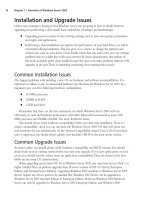
As part of your PIX firewall troubleshooting knowledge, you need to know the pinout
scheme used by this cable.To that end, we have provided a detailed schematic in Figure 11.11. If
failover is not working, you need to know what your cable configuration should look like when
you analyze it with a cable tester.
Although all the wires in the DB15 connector at each end are important, you can see that
certain wires are cross-connected at each end to distinguish the primary end from the secondary
end.The primary firewall is configured by cross-connecting wire 11 (local plug detect) to wire
12 (primary select).The secondary firewall is determined by cross-connecting wire 12 (secondary
select) to wire 5 (ground). Knowing the wiring scheme can enable you to not only to check
your failover cable, but to also build one from scratch if necessary.
Checking Translation
The PIX firewall performs address translation. In order for internal networks to communicate
with external networks, and vice versa, addresses must be translated.Translation is not optional.
The translation is the act of translating one IP address to another, which can be configured as one
to one (NAT) or many to one (PAT).
NOTE
To pass traffic through the PIX traffic, you must translate it, even if this means you will
translate IP addresses to themselves.
www.syngress.com
Figure 11.11 Failover Cable Pinout
8
5
4
3
2
1
14
13
12
11
10
9
15
8
7
6
5
4
3
2
1
14
13
10
9
15
12
11
Internal Loopback
Internal Loopback
Primary Secondary
Power Dectect
Foreign Plug Detect
Receive Data
Power Source
Transmit Data
Local Plug Detect
Plug Driver
Primary Select
Ground
Secondary Select
6
7
252_BDFW_ch11.qxd 9/18/03 4:57 PM Page 389