the best damn firewall book period phần 5 pdf
Bạn đang xem bản rút gọn của tài liệu. Xem và tải ngay bản đầy đủ của tài liệu tại đây (2.17 MB, 133 trang )
498 Part IV • Check Point NG and Nokia IP Series Appliances
is no reverse record, the object will be useless. It is also possible that, through DNS poisoning, this
sort of object could lead to a security breach. For these reasons and others, Check Point does not
recommend the use of domain objects in your rule base. If you decide to use them, use them as
close to the bottom of the rule base as possible.
OSE Device
Open Security Extension technology allows FW-1 to manage third-party devices that support
these extensions. Most notable among these devices are Cisco routers running IOS v9 and later.
The number of devices that you may manage depends on your license.The configuration for an
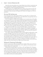
OSE compliant device features three windows.To create a new OSE Device, select New | OSE
Device from the Network Objects management window. Figure 13.9 illustrates the General
window.
This window enables you to specify some of the basic information about the device, specifically
the IP address, name, comment, and device type.The device type may be any of the following:
■ BayRS
■ Cisco
■ 3Com
When a device from this category is managed by the firewall, access control lists are gener-
ated based on the security policy and downloaded to the firewall.As with other object types, the
Get address button will attempt to resolve the specified name to an IP address, saving you that
one step.
The topology window is identical to that of its counterpart for the other devices.The main
caveat is that at least one interface must be defined (as opposed to, say, a simple workstation) or
the ACL entries will not be created successfully. Anti-spoofing and its kin are also defined by
editing the interface properties, just as with a workstation. However, there are some additional
steps to take, which are accomplished by editing the information on the Setup window.
www.syngress.com
Figure 13.9 OSE Device—General Window
252_BDFW_ch13.qxd 9/18/03 5:02 PM Page 498
Using the Graphical Interface • Chapter 13 499
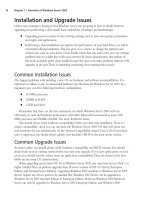
The Setup window varies depending on the OSE Type specified on the General window.The
window as displayed with a Cisco router is displayed in Figure 13.10.
The fields displayed on this window have the following meanings:
■ Access List No. The number of the ACL that will be applied.
■ Username This is the exec mode username that will be used for initial access to the
device. It, along with the remaining drop-down lists, can be set to None, Known,or
Prompt. If set to Known, the gray box to the right will become active and allow the
entry of a username.
■ Password Enter the password associated with the exec mode username.
■ Enable Username The name, if any, of a user with privileged exec access.
■ Enable Password The password associated with the privileged username.
■ Version IOS version installed on this router.
■ OSE Device Interface Direction The direction in which to enforce the security
policy.This can be Inbound, Outbound, or Eitherbound.
■ Spoof Rules Interface Direction The direction in which to enforce anti-spoofing
behavior.This can be Inbound, Outbound, or Eitherbound.
The fields for the 3Com and Bay devices are similar in their requirements, and the security
policy is enforced in an identical manner.
Embedded Device
An embedded device is defined as a device on which a VPN/FW-1 module or Inspection
module is installed.This type of object is restricted to two types (as defined in the Type field)
with those being Nokia IP5x and Xylan with the supported platforms being Ramp and Xylan.
The configuration is pretty straightforward, with the common rules applying. Define the
name, IP address, and an optional comment.Then specify the type, and select VPN-1 &
www.syngress.com
Figure 13.10 Cisco OSE Setup Window
252_BDFW_ch13.qxd 9/18/03 5:02 PM Page 499
500 Part IV • Check Point NG and Nokia IP Series Appliances
FireWall-1 installed if applicable.You must also define your license type. Figure 13.11 illustrates
the configuration panel.To open this panel, select New | Embedded Device.
Group
The Group object can be used to manage other objects of dissimilar types.There are three types
of groups that you may define within FW-1.To create a new group, select New | Group from
the Network Objects management window.The group types are as follows:
■ Simple Group
■ Group with Exclusion
■ UAS High Availability group
A simple group is just that. Simple. It is a collection of network devices.The second group
type, Group with Exclusion, allows you some granular control over the contents of a group. If
you are working in a network with a flat topology, for example, you may be in a situation where
there isn’t much physical separation within this network. A group of this type enables you to
force some structure here. Figure 13.12 illustrates a simple group.
www.syngress.com
Figure 13.11 Embedded Device General Properties
Figure 13.12 Group Properties
252_BDFW_ch13.qxd 9/18/03 5:02 PM Page 500
Using the Graphical Interface • Chapter 13 501
A Group with Exclusion is slightly different than a Simple group, with the difference being
that you specify a major group, defined by Check Point as an “outer group.”This will be the
group that is included for this definition.You then specify minor, or inner, groups.These will be
the groups culled out and excluded from the major group.
Logical Server
The logical server group (available by selecting New | Logical Server from the Network
Objects window) enables you to group like servers (FTP, HTTP, SMTP, etc) to be treated as one
and used in a sort of resource sharing, or server pooling. Note that this is an optional feature and
may not be included with your FW-1 installation. Workload is distributed among these servers in
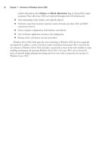
a user-configurable manner. Figure 13.13 shows the configuration options for this object type.
As usual, the name must be entered, and, if resolvable, the Get address button can be used
to gather the associated IP address.A special note is in order here, specifically regarding the IP
you’ll select.This address should be that of a non-existent server located on the same network as
the destination servers, but can also be that of the FireWall-1 module.Think of this IP as a virtual
IP address. It will be used by the clients to connect to the Logical Server group, and therefore
cannot belong to any one member of that group.
The Server’s Type feature really is poorly named.This actually defines the method of load
balancing, or even more specifically, the type of algorithm used.The two methods behave very
differently. For example, with HTTP selected, only the initial connection will be handled by the
logical server address. A redirection is sent to the client informing his or her browser of the new
IP (that of the selected destination server), and the remainder of the conversation goes forth
without the intervention of the firewall module. If Other is selected as the type, address transla-
tion is performed and the conversation is balanced per connection, with the firewall module con-
stantly involved, unless Persistent Server mode is checked.
The Servers section enables you to select the server group that will make up this logical
group. If selected, Persistent server mode allows some fine-tuning of the balancing mechanism.
When enabled, you can enforce connection persistence, meaning you can force packets from an
established flow to continue to a single destination.This is very useful for something like an
www.syngress.com
Figure 13.13 Logical Server Properties Window
252_BDFW_ch13.qxd 9/18/03 5:02 PM Page 501
502 Part IV • Check Point NG and Nokia IP Series Appliances
HTTP conversation when using Other as the server type.You can select between two modes
here, Persistency by service and Persistency by server.The main difference between the two
is that, when the former is selected, only connections to a single server for a single service will
have persistency enforced, while in the latter any service on a specific server will be impacted.
The final settings define the type of balancing to be performed.The Balance Method has sev-
eral possible options.
■ Server Load FW-1 sends a query, using port 18212/UDP, to determine the load of
each server.There must consequently be a load-measuring agent on each server to sup-
port this method.
■ Round Trip FW-1 sends a simple ICMP ping to each server.The fastest round-trip
time is chosen as the preferred server.This lacks somewhat, in that the ping is from the
firewall to the server, and may not be optimal from a remote client (remember, the
servers need not be centrally located to participate in a server group). Also, a ping
doesn’t tell you that the HTTP daemon has crashed on the server.As long as the server
is up and on the network, regardless of the status of any of its services, traffic will be
sent to it.
■ Round Robin FW-1 selects sequentially from a list.This is among the simplest methods.
■ Random FW-1 selects randomly from a list.
■ Domain FW-1 attempts to select the closest server to the client, based on domain
naming convention.This method is not recommended.
Address Range
An address range defines a sequential range of IP addresses for inclusion with your rule base. An
address range is similar in use to a network object, with the major difference being that you
specify a starting and ending IP address instead of a network number and subnet mask. Figure
13.14 illustrates the General panel for this object type, which is available by selecting New |
Address Range from the Network Objects management window.As usual, the NAT panel fea-
tures no special information and is the same as that found on most other object types.
www.syngress.com
Figure 13.14 Address Range Properties Window
252_BDFW_ch13.qxd 9/18/03 5:02 PM Page 502
Using the Graphical Interface • Chapter 13 503
Gateway Cluster
A gateway cluster is a grouping of machines running VPN-1/FW-1 that is grouped together as a
means of fail-over support. Clustering is a complex subject, and configuring it is much more
detailed than the majority of other object types. First, you have to visit the Global Properties
and, under the Gateway High Availability branch, place a checkmark in the setting to Enable
gateway clusters.
The next step is to create your workstation objects. In order to support clustering, you must
have at least three objects, two of which must be firewall modules, and one a manager.The work-
station object should be created as normal for a machine with FW-1 installed. It is important that
the interfaces are properly defined, as anti-spoofing is required for proper high-availability func-
tion. Next, you create a new gateway cluster object.The General panel is illustrated in Figure
13.15.You’ll access this panel by selecting New | Gateway Cluster from the Network Objects
management window.
This panel allows the initial configuration for the cluster.The name and IP address are
defined here, as are the specific Check Point products that will reside within this cluster.Also, you
can specify whether you or another party manage the cluster.You also can specify, on the
topology panel, which addresses reside behind this cluster.This is similar to the features on a
workstation object’s interface properties topology panel.
Dynamic Object
A dynamic object is perhaps the most interesting object type supported on FW-1. It is also one of
the most useful in a large enterprise.This object type enables you to define a logical server type,
one in which the actual IP address will resolve differently on each FW-1 machine.This enables
you to create rules referencing “mail server” and distribute that policy to several different FW-1
machines, all of which will resolve “mail server” as the proper machine within their realm. Figure
13.16 shows you the basic configuration window, which you can see by selecting New |
Dynamic Object from the Network Objects management window.
www.syngress.com
Figure 13.15 Gateway Cluster—General Panel
252_BDFW_ch13.qxd 9/18/03 5:02 PM Page 503
504 Part IV • Check Point NG and Nokia IP Series Appliances
The real key to a dynamic object is the dynamic_objects command.This command is run on
the firewall module where the name will be resolved, and enables you to specify the values to
which it will resolve.Table 13.2 describes this command and its options.
Table 13.2 Dynamic_Objects Command Options
Option Explanation
-o <object name> Specify the object name to work with. This option is often used with
operators such as –a to add addresses to an existing object.
-r <address range> Specify an address range.
-a <address range> Add address of <range> to object.
-d <address range> Delete addresses from the object.
-l List all dynamic objects.
-n <object name> Create a new dynamic object; assuming the VPN-1/FW-1 process has
been stopped.
-c Compare the defined dynamic objects to those defined in the
objects.C file.
-do <object name> Delete the specified object.
Services
The services objects give you a finer level of access control as compared to exclusive use of net-
work entities. With the service object, you can define protocol specific information, like protocol
in use (TCP, UDP, and so forth), and port numbers. FW-1 comes preconfigured with many of the
more common services in use today, and further enables you to create custom services based on
your unique needs.
To add, modify, or delete services, access the Services window by clicking Manage |
Services. From here, you will be able to act on the following service types.
www.syngress.com
Figure 13.16 Dynamic Object Properties Window
252_BDFW_ch13.qxd 9/18/03 5:02 PM Page 504
Using the Graphical Interface • Chapter 13 505
TCP
The TCP service object enables you to define a basic TCP service. Figure 13.17 illustrates this
service type, using the domain-tcp (DNS) service as an example.To bring up this window, select
New | TCP from the Services management window.
The information required for this service is very limited (which is nice when you have to
define a lot of them!). Besides a name and comment, all you have to enter is the destination port
number.This can be a specific port, as in Figure 13.17, a range (e.g. 1024-1028), or a greater-
than/less-than definition (e.g. <56).There is also an Advanced button, which displays the
window as shown in Figure 13.18.
The Advanced settings enable you to specify a source port, and allow for the same modifiers
as in the General panel’s port specification.You can also specify the protocol type, which impacts
which security server will provide things like content security for this service.The checkbox
marked Enable for TCP resource, if checked, enforces screening using a UFP server, mitigating
the intervention of a security server.The next item, Match for ‘Any’ allows connections using
this service to be matched when a rule is crafted with ‘Any’ as the service.The Session Timeout
is a local setting meant to allow override of the global session timeout.The inclusion of the
timeout in the GUI is a nice change for FW-1 NG. In previous versions, setting a per-service
timeout required manual editing of the base.def file, which is obviously a bit more involved.
www.syngress.com
Figure 13.17 TCP Service Properties
Figure 13.18 Advanced TCP Service Properties
252_BDFW_ch13.qxd 9/18/03 5:02 PM Page 505
506 Part IV • Check Point NG and Nokia IP Series Appliances
UDP
The UDP service object enables you to define a basic UDP service. An example of this is the
TFTP service. UDP tracking poses a problem for many firewalls, especially circuit level gateways.
Since UDP is connectionless, it’s generally an all-or-nothing approach to security. Whole port
ranges are often opened to allow UDP traffic, which is not a very nice notion. With FW-1, a
second mechanism has been designed to keep track of a virtual “connection.”
The General properties are identical to those for TCP, as seen in Figure 13.17.The Advanced
options are slightly different, and are shown in Figure 13.19.
As with the TCP settings, we are able to specify a source port and a protocol type.
Additionally, we have the familiar checkboxes, but this time with slightly different values.These
are as follows:
■ Accept Replies If checked, allows for a bi-directional communication to take place.
■ Accept replies from any port Allows the server to reply from any port. An example
of the need for this is the TFTP service.
■ Match for ‘Any’ Allows connections using this service to be matched when a rule is
crafted with ‘Any’ as the service.
RPC
RPC services are usually tricky for a firewall administrator. RPC-based connections do not use a
fixed port number, so allowing these types of connections is either an all-or-nothing exercise.
Usually, administrators choose to block all RPC connections on their external firewalls, while
being far more permissive within their network boundaries.
To alleviate this potential risk, FW-1 transparently tracks RPC ports. Application information
is extracted from the packet in order to identify the program used. FW-1 also maintains a cache
that maps RPC program numbers to the assigned port numbers.The configuration panel, viewed
by selecting New | RPC from the Service management window, is shown in Figure 13.20.
www.syngress.com
Figure 13.19 Advanced UDP Service Properties
252_BDFW_ch13.qxd 9/18/03 5:02 PM Page 506
Using the Graphical Interface • Chapter 13 507
ICMP
ICMP is used for things like network troubleshooting and discovery. Unfortunately, attackers
looking to gain information about you can also use it. For this reason, many sites decide to block
all ICMP traffic.This isn’t really necessary, and may cause more problems than it solves.You can,
using FW-1, pick and choose the specific ICMP types (and even sub types, or “codes”) allowed.
Table 13.3 details some of the more useful ICMP types, their associated codes, and their mean-
ings, as defined by the IANA (www.iana.org/assignments/icmp-parameters).
Table 13.3 ICMP Codes
ICMP Type ICMP Code Explanation
0 Echo (ping) reply
3 Destination unreachable:
0 -network unreachable
1 -host unreachable
2 -protocol unreachable
3 -port unreachable
4 Dropped because DF (do not fragment) bit was set,
fragmentation needed
5 Source routing not allowed or otherwise failed
4 Slow transmission rate
5 Better network path available:
0 -for entire network
1 -for specific host
2 -for tos and entire network
3 -for tos and specific host
8 Echo (ping) request
11 Time exceeded for reason:
0 -TTL reached 0 in transit
1 -fragment reassembly time exceeded
12 Bad IP header
www.syngress.com
Figure 13.20 RPC Service Properties
252_BDFW_ch13.qxd 9/18/03 5:02 PM Page 507
508 Part IV • Check Point NG and Nokia IP Series Appliances
Figure 13.21 shows us the configuration panel for an ICMP service. Using Table 13.3, you
can see how simple it would be to create services, and thus rules, to allow the beneficial types of
ICMP while excluding those that may do you harm.
Other
Often called user-defined services, this is a catchall for whatever is missing. Its presence gives you a
great deal of flexibility, but requires at least a familiarity with the inspect language.The General
panel is similar to that found in its cousin objects, allowing you to define a name, add a com-
ment, and assign a color. It also enables you to define the protocol identifier.This is a very
important field, as it is the key to matching against the incoming traffic. Figure 13.22 shows you
the General panel for this service type.
Clicking the Advanced button brings up a screen that allows the entry of the most crucial
part of this object, the Match field.This field is a snippet of inspect code that will be used to
check the incoming packets. It can, therefore, be as complex as you can imagine.This makes the
user-defined object a truly powerful tool for the enforcement of very specific requirements.
Group
The group object enables you to combine different protocols.This can be used, for example, to
define a service whose individual parts must also be separately defined. Ping is a good example. It
consists of an echo request and an echo reply.These can be defined and then combined into a
group, and that group used in your rule base. Figure 13.23 displays the configuration window,
which is accessed by selecting New | Group from the Services management window.
www.syngress.com
Figure 13.21 ICMP Service Properties
Figure 13.22 User-Defined Service Properties—General Panel
252_BDFW_ch13.qxd 9/18/03 5:02 PM Page 508
Using the Graphical Interface • Chapter 13 509
DCE-RPC
This service type works in a similar fashion to the RPC service, in that it tracks DCE-RPC
based connections, extracting the information from the packet and creating a virtual session
whose information is stored in a local cache. When you define the DCE-RPC service, you will
be asked for the UUID for the specific interface as well as the protocol type. Figure 13.24 illus-
trates this panel.
Resources
Resource objects are used to configure Content Security on FW-1. Content security includes
support for the HTTP, FTP, and SMTP protocols. FW-1 provides this support by using the FW-1
Security Servers. For each connection established through the FW-1 Security Servers, you are
able to control access on a granular level according to protocol specific information unique to a
specific service.This includes URLs, file names, FTP commands, and so on.
Uniform Resource Identifier
A Uniform Resource Identifier (URI) defines how to access resources on the Internet. Most of
us are familiar with the URI by another name: URL. Which term you use is often a matter of
tossing the dice, as there is dispute even among the standards developers as to which is more proper.
www.syngress.com
Figure 13.23 Group Properties
Figure 13.24 DCE-RPC Properties
252_BDFW_ch13.qxd 9/18/03 5:02 PM Page 509
510 Part IV • Check Point NG and Nokia IP Series Appliances
URI for QoS
Another type of URI object is the URI for QoS, which is used when defining a rulebase for
FloodGate-1.This resource type allows the security administrator to classify certain URIs as part
of a QoS policy.This object type is fairly simple to create.You’ll need to define a name, com-
ment, and select the color for the object. Additionally, you will need to define a Search for
URL.This specifies the URL that will trigger a match, and it can be as specific as a complete
URL, or as general as *.jpg, which would match any JPEG file.
SMTP
The SMTP resource defines the methods used by the FW-1 to handle incoming or outgoing e-
mail.There are many options, including the ability to remove active scripting components,
rewriting fields in the envelope (such as To: or From:) or filtering based on content.The configu-
ration of this resource type is similar to that of the URI, including the ability to use a CVP server.
FTP
An FTP resource is defined in order to enforce content security for FTP connections. We like to
use this resource to define the verbs or methods that will be allowed through my firewall. For
example, if we have an FTP server that is publicly available for downloading, we can back up the
system administrator and deny the ability to PUT.
Open Platform for Security Applications
The Open Platform for Security (OPSEC) object defines for you a means of interacting with a
third-party developed security application.These applications add extended functionality to the
FW-1 installation. Some examples include virus scanning, content filtering, and intrusion detec-
tion. OPSEC allows FW-1 to send its data stream to other applications, and it also allows those
applications to send data to the firewall, for example, log entries via the ELA or status via AMON
interfaces.
Servers
A server is a host computer running a specific application or service.The server object is the rep-
resentation of that relationship.
Radius
A RADIUS server is used to provide authentication services. While originally used for remote
access services, it is also now commonly used for things like routers and firewalls.To define a
radius server, select Manage | Servers from the policy editor drop-down menu and then select
New | RADIUS.The configuration appears as in Figure 13.25.
The RADIUS server object is configured in a way that is fairly common with the other
server types.After defining the name, adding a comment, and selecting the associated color, you’ll
need to specify the Host that this RADIUS server is running on.You’ll also need to assign a
Priority.The priority is used to determine the preference for an individual server when more
than one is available for contact, for example, when the server is assigned to a RADIUS group.
www.syngress.com
252_BDFW_ch13.qxd 9/18/03 5:02 PM Page 510
Using the Graphical Interface • Chapter 13 511
The next step is to define the Service, which is the obvious choice of RADIUS.The
Shared Secret must be entered in order to establish communication between the firewalled
object and the RADIUS server. Consequently, it must be the same on both devices.The final
step is to select the proper version from the Version drop-down menu.
Radius Group
A RADIUS group is used to form a group of RADIUS servers.These servers are then available
for use as a single object, with authentication services being performed by the server with the
highest priority (e.g. the lowest number). Unlike most other groups, server groups such as this
may not contain any dissimilar entities.
TACACS
A Terminal Access Control Access Control Server (TACACS) server is another one of your handy
access control methods.The definition of this object shares the same generalities of the other
server entities, those being name, comment, color, and host. Once these are defined, you have
only to specify if the server is running TACACS or a TACACS+, enter a secret key, if necessary,
for TACACS+, and select the appropriate Service from the drop-down menu. (Note that you
won’t have to select a service with TACACS+.) This panel is illustrated in Figure 13.26.
Defender
The Defender server type defines an object running AXENTs Pathways Defender server.This is
another authentication method available to you as a FW-1 administrator, and is very easy to
www.syngress.com
Figure 13.25 RADIUS Server Properties
Figure 13.26 TACACS Server Properties
252_BDFW_ch13.qxd 9/18/03 5:02 PM Page 511
512 Part IV • Check Point NG and Nokia IP Series Appliances
incorporate. Besides your four familiar fields of Name, Comment, Color, and Host, you are also
able to specify a backup host.Then all that remains is to enter the Agent ID, as defined on the
Defender server, and the Agent Key, which is used to encrypt the communication with the
Defender server, and is also specified in the Defender server’s configuration.
Lightweight Database Access Protocol Account Unit
The Lightweight Database Access Protocol (LDAP), is used for a bevy of purposes. With regards
to FW-1, this server object is used for the purposes of user management. A full discussion of the
workings of LDAP is beyond the scope of this book but we’ll assume if you are configuring an
LDAP object, you have access to an existing LDAP server and the necessary information. Figure
13.27 illustrates the General panel for LDAP configuration.
Certificate Authority
We’ve all heard the buzz about PKI, now here’s your chance to jump on the bandwagon.The
inclusion of a certificate authority in your security infrastructure enables you to use certificate-
based authentication and encryption that eases (or perhaps shifts) the administrative burden of
VPN development.
There are three tabs for the Certificate Authority object, with the first being the very simple
General tab.The associated panel allows the standard configuration information of Name,
Comment, and Color, as well as the ability to specify the Certificate Authority via a drop-down
menu.You’ll have a few choices in this drop-down, with your selection determined by what is
available to you.The contents of the second panel depend on the selection in this drop-down box.
The contents of the second panel vary, but generally allow for the importing of a configura-
tion from the PKI server and the importing of the actual certificate.You may also be able to
specify the source of the Certificate Revocation List (CRL).
The Advanced panel deals with the CRL for this server; specifically, it configures the desire
to cache the CRL and when to fetch a new CRL.You can also assign what branches are to be
allowed.
www.syngress.com
Figure 13.27 LDAP Account Unit Properties
252_BDFW_ch13.qxd 9/18/03 5:02 PM Page 512
Using the Graphical Interface • Chapter 13 513
SecuRemote DNS
SecuRemote DNS is an internal server type that is used to resolve private addresses to names.
SecuRemote DNS replaces the need to create a dnsinfo.C file on the management server’s
$FWDIR/conf directory.This is a nice change.You will, however, still need to edit
$FWDIR/lib/crypt.def though, adding the line #define ENCDNS to enable SecuRemote users
to download this information along with their topology.
Configuration of this server type is fairly straightforward.You have two tabs: General and
Domains.The General panel allows the configuration of the Name, Comment, Color, and
Host. As usual, the host must have previously been defined as a workstation object.
The Domains panel lists the domains that are included for resolution, as well as something
called a Maximum Label Prefix Count.This count defines the number of prefixes that will be
allowed for the specific domain. For example, if the domain is .edu, then troll.gatech.edu has two
prefixes. If the maximum prefix count was one, this domain would not resolve.
Internal Users
The ability to define users on the firewall is a nice feature, but it is also rather administratively
intensive.The benefit is that you can select specific users as the source for traffic in a rule.The
downside is you have to define these users. Fortunately, Check Point has simplified this process
somewhat with the ability to define generic user templates.The use of LDAP as an external
source of user information is also supported, which greatly decreases the workload redundancy of
a firewall administrator.
The first step is to bring up the Users interface.This is accessed by selecting Manage |
Users from the policy editor menu.This window is used to define and modify users, and also to
install the user database to the VPN-1/FW-1 systems on which this policy is installed.
Time
Time objects are just that.These objects enable you to schedule events, restrict connections, or
simply quantify a time period. For example, you can restrict Web browsing not only to specific
sites, but also to specific times.There are three possible object types to select from.You can
specify a time, a scheduled event, or a group of one or more of these types.To create a new time
object, simply select Manage | Time from your policy editor window.
The time object is used to restrict the application of rules to specified times.There are two
panels to this object: General and Days. The General panel allows the standard settings, as well
as up to three time ranges.These ranges specify the time spans in which this object would be
applicable.The second panel, Days, enables you to enforce a finer-grained access control on the
time object. We can specify days of a week, or a specific date, or a numbered day in each month.
Figure 13.28 illustrates the Days panel.
www.syngress.com
252_BDFW_ch13.qxd 9/18/03 5:02 PM Page 513
514 Part IV • Check Point NG and Nokia IP Series Appliances
Group
A group is formed by the combination of several time object types, and can be used to simplify
time-based rules. Instead of using multiple rules, you can create a group of time objects and
assign this to a single rule. Creating a time group is similar to the other group types, and consists
of assigning a name, comment, and color and then moving time objects from the Not in Group
list to the In Group list.
Scheduled Event
A scheduled event is most often used for administrative purposes, such as scheduling log changes.
Configuration is simple, with the only interesting field being the specification of the time at
which the event will be triggered.You can also, as with the time object, schedule the repetition
frequency of the object. For example, when you define your Management machine, you have
access to the Management branch of the Workstation properties. One of the fields, Schedule log
switch to:, requires the use of a time object as its option.
Virtual Link
A Virtual Link is a path between two VPN-1/FW-1 modules or FloodGate-1 Modules. Virtual
Links are defined in the Policy Editor, and can be given Service Level Agreement (SLA) parame-
ters.They can then be monitored using Check Point Traffic Monitoring.To add a new Virtual
Link, select Virtual Links from the Manage menu in the Policy Editor.
There are two panels to be configured.The General panel defines the name, etc., for the
link, and also enables you to define the endpoints and to optionally activate the link.
The SLA Parameters panel, shown in Figure 13.29, enables you to specify the criteria that
will be used to measure the integrity of the link.Thresholds are defined in three directions of
traffic.You can specify the Committed Information Rate (CIR) for traffic point A to point B, and
the reverse as well.You can also specify a maximum round trip time (RTT) for bi-directional
communication, and optionally log the SLA statistics.
www.syngress.com
Figure 13.28 Time Object—Days Panel
252_BDFW_ch13.qxd 9/18/03 5:02 PM Page 514
Using the Graphical Interface • Chapter 13 515
Adding Rules
The Policy Editor is the main interface for all your firewall needs.This is where we have been
working to add objects, but it is also the interface to define rules. In the next few sections, we’ll
show briefly how the Policy Editor can be used to put your network objects into play in the
form of firewall rules.
Rules
FW-1, like most firewalls, is designed to enforce a set of rules, known as a rule base.This rule base
defines the behavior of the firewall, and is configured by you, the firewall administrator. It is
dreadfully important that you carefully consider the underlying needs, related to both security
and functionality, and make a measured application of both.You’ll probably never be able to strike
a perfect balance, but the closer you come, the easier your life will be. Fundamentally, there are
two models of firewall configuration.The first considers all traffic to be suspect, and only allows
what is necessary (blocking all not explicitly allowed).The second model is far more permissive,
allowing all traffic that has not proven to be risky (allowing everything except what is explicitly
denied). Which model you subscribe to is a decision that must be made at the policy level.Your
firewall will be a technical implementation of that policy.
A rule is made up by the combination of source, destination, action, tracking information,
enforcement location, enforcement time, and an optional (but highly recommended) time fields.
These fields are explained in the next few sections, along with the methods used to create them.
Adding Rules
Adding rules in FW-1 is very straightforward.There are a few choices about rule placement you
have to decide upon when adding a new rule. When you select Rules | Add Rule you’ll see a
submenu with the following choices.
■ Bottom After the last rule in the rulebase.
■ Top Before the first rule in the rulebase.
www.syngress.com
Figure 13.29 Virtual Link Properties—SLA Parameters
252_BDFW_ch13.qxd 9/18/03 5:02 PM Page 515
516 Part IV • Check Point NG and Nokia IP Series Appliances
■ After After the currently selected rule.
■ Before Before the currently selected rule.
After you insert the new rule, it will resemble the one shown in Figure 13.30.You will need
to configure the specifics of each rule. In each field of the new rule, right-click to enter the nec-
essary information.
Source
The source field defines the IP address or hostname that is initiating the data stream. For the sake
of your rule base, the source can be any of the properly defined network objects, as well as users
or groups of users. When adding a source, you have the choice of adding an object or adding user
access.You are not restricted in the number of sources for a rule.
Destination
The destination can be any defined network object. When you right-click in the Destination
field and select Add, you’ll see a window similar to that shown in Figure 13.31. Note that a rule
can support multiple destinations.
Service
The service field defines the service that must be present in order to generate a match.To add a
service, right-click in the Service field and select Add. You will have the choice of adding a ser-
vice, or a service with a resource.You can define any number of services for a rule.
Action
The action is the way that FW-1 reacts when a rule is matched.You have a couple of choices
when selecting an action, but only one selection is allowed.The available options are the following:
www.syngress.com
Figure 13.30 New Rule
Figure 13.31 Add Object
252_BDFW_ch13.qxd 9/18/03 5:02 PM Page 516
Using the Graphical Interface • Chapter 13 517
■ Accept Accept the packet; allow the connection.
■ Reject Reject the connection and notify the sender of the condition.
■ Drop Reject the connection, but do not notify the sender.
■ User Authentication Use User Authentication for this connection.
■ Client Authentication Use Client Authentication for this connection.
■ Session Authentication Use Session Authentication for this connection.
■ Encrypt Encrypt outgoing packets; decrypt incoming packets.
■ Client Encryption Accept only if this connection originates from a SecuRemote client.
Track
The Track column defines how information about this session will be recorded.There are several
options in the menu when you right-click on this field.
■ Log Write a log entry regarding this connection.
■ Account Write an accounting log entry regarding this connection.
■ Alert Generate a pop-up alert regarding this connection.
■ Mail Send a mail regarding this connection.
■ SnmpTrap Generate an SNMP trap based on this connection.
■ User-Defined Execute the user-defined script as a result of this connection.
Install On
The Install On field defines which defined objects will have this policy installed on them.
Although the entire policy is installed on each selected object, these objects only enforce the part
of the policy that is relevant to them. If no rules are relevant, then no communication will be
allowed.
■ Enforce on all network objects defined as gateways.
■ Enforce on the specified target object(s) only, in the inbound and outbound directions.
■ Enforce in the inbound direction on the firewalled network objects defined as
Destination in this rule.
■ Enforce in the outbound direction on the firewalled network objects defined as Source
in this rule.
■ Enforce on all OSE devices.
■ Enforce on all embedded devices.
www.syngress.com
252_BDFW_ch13.qxd 9/18/03 5:02 PM Page 517
518 Part IV • Check Point NG and Nokia IP Series Appliances
Time
In this field, use a time object to restrict the connection to certain specified intervals, or leave the
default of Any.
Comment
This field is used to describe the rule, its purpose, and its functionality. It is highly recommended
that you do not leave this field blank!
Global Properties
While the brunt of your security policy will reside in the rule base, there are other places you
have to pay attention to. In order to fully secure your enterprise, you will need to at least be
familiar with the Global Properties, and most likely you will need to alter them.You do this by
accessing the Global Properties from the Policy menu. We’ll spend the next few sections dis-
cussing these properties. Figure 13.32 displays the initial panel of the Global Properties.
FW-1 Implied Rules
FW-1 has a feature that many find mysterious at first blush.That feature is the implied rule base.
This rule base is made up of settings in the Global Properties, as opposed to the one explicitly
created by you, the firewall administrator. Once you understand this, the mystery is removed, and
you’ll see that they are actually pretty simple.They are shown, by the way, in Figure 13.32. What
you select is up to your security policy, but we highly recommend that you enable the logging of
these rules.
One important thing to understand is the implication of the option values. If you select a
rule to be included within the implied rule base, you’ll need to decide where to place that rule.
You have three choices here.
■ First
www.syngress.com
Figure 13.32 Global Properties
252_BDFW_ch13.qxd 9/18/03 5:02 PM Page 518
Using the Graphical Interface • Chapter 13 519
■ Last
■ Before Last
You’ll need to select the location in the rule base where the selected rule will be placed.This
is a critical decision, and you should understand how a packet passes through the rule base in
order to assist your decision. Furthermore, not all implied rules are as simple as they may seem.
The first implied rule, Accept VPN-1 and FW-1 control connections, for example, enables a ser-
vice group containing 17 services.You probably don’t need to worry about this too much, but it
is a good thing to be aware of.
Viewing Implied Rules
There are two methods of viewing implied rules. Certainly, you can view them within the Global
Properties window, but this is often cumbersome and difficult to do in a cohesive flow. When you
want access to these rules while editing the rest of your rule base, the easiest way is to select the
View menu and then select Implied Rules.You’ll see something like what is displayed in Figure
13.33. Note that the implied rules are unnumbered and are highlighted by their different color.
SYNDefender
SYNDefender is a feature used to guard your network from the dreaded SYN flood. Note that
this isn’t really designed to prevent such an attack against your firewall, but for what it is intended
to do it is very handy. It has two modes of operation: SYNGateway and passive SYNGateway. In
SYNGateway mode, the firewall actively intercepts SYN packets, completes the three-way hand-
shake, and only then forwards the connection to the true destination. In passive mode, the firewall
monitors the connection. If the timeout period is reached, a RST (reset) packet is sent to both
the originator and the destination.
Configuring SYNDefender is simple. Simply navigate to the proper sub-menu and select the
method, timeout, and maximum connections.
Using SYNDefender to Defend the SYN Attack
The SYN attack is one of the simplest Denial of Service (DoS) attacks to initiate. Unfortunately,
it is also one of the most difficult to defend against.The reasons for these truths are identical.The
basic operation of a SYN flood is to send hundreds of thousands of connection requests (SYN, or
synchronize, packets) to the target server.The target server will send an acknowledgment of that
www.syngress.com
Figure 13.33 Implied Rules
252_BDFW_ch13.qxd 9/18/03 5:02 PM Page 519
520 Part IV • Check Point NG and Nokia IP Series Appliances
SYN packet, allocate a bit of memory in a pending connection queue, and then wait, for a prede-
fined timeout period, for the final part of the connection process to complete. Herein lies the rub.
There are two problems here.The first is that the sending of a SYN packet is completely
normal. A high-volume server might see thousands of SYN packets in any given time period.
The second problem is that the server tends to be too generous in its timeout period, giving the
client plenty of time to complete the connection. For example, default configuration of Microsoft
Windows 2000 will wait 189 seconds.That’s over three minutes per connection of resource con-
sumption. While the memory allocated is small, the cumulative impact can be severe enough to
gobble up all the resources on the target server.
While firewall tools like SYNDefender can help you keep the bogus SYN packets from
reaching the server, you need (and have available) a better method. Since most SYN attacks use
spoofed IP addresses, ingress and egress filtering by large ISPs could go a long way to mitigate the
dangers of SYN attacks.
Security Server
The Security Server panel allows the entry of welcome messages for many of the most common
Internet services.This is accomplished by pointing to the appropriate file containing the message.
You can also configure the HTTP Next Proxy, although this is better done in the workstation
object, assuming a version of FireWall-1 of NG. Earlier versions still require entry in this field.
Authentication
The Authentication panel enables you to specify the tolerance for failed login attempts.There are
parameters for rlogin, telnet, client authentication and session authentication.There is also a sec-
tion for configuring session timeout, wait mode and logging/alerting for back level modules.
VPN-1
The VPN panel controls the configuration of items like security association (SA) renegotiation, as
well as CRL and SecuRemote grace periods.
Desktop Security
The Desktop Security panel contains a lot of information regarding the behavior of your firewall
with regard to SecuRemote client requests.The settings you select here are highly dependant on
your own security policy, but again, WE strongly recommend that you log violation notifications
and not respond to unauthenticated topology requests.
Visual Policy Editor
The Visual Policy Editor (VPE) provides a very slick interface to view your objects and their
interrelations, as mentioned in the beginning of this chapter.This panel enables you to display the
VPE or conceal it from view. Note that if you disable the VPE, no topology calculations will take
place within the firewall inner workings.
www.syngress.com
252_BDFW_ch13.qxd 9/18/03 5:02 PM Page 520
Using the Graphical Interface • Chapter 13 521
Gateway High Availability
Gateway High Availability is the process in which multiple modules can act as one for the sake of
redundancy.This panel lets you enable or disable the feature.
Management High Availability
Management High Availability is similar to that for gateways, except that it allows the manage-
ment modules to exhibit some redundancy.This panel allows for you to select the synchroniza-
tion time of the management servers participating in the HA configuration.
Stateful Inspection
Stateful Inspection is the heart of FW-1.This panel does not allow you to change that, but instead
enables you to specify some timeout settings for the TCP sessions and to configure stateful UDP
and ICMP behavior.
LDAP Account Management
The LDAP account management panel allows the enabling of LDAP for account management.
Here you can also set some session timeouts and password rules.
Network Address Translation
The NAT panel configures some general NAT behavior such for the Automatic NAT rules and
NAT pools for SecuRemote connections.
ConnectControl
The ConnectControl panel allows the configuration of this very handy feature. On this panel, we
can set the interval that VPN-1/FW-1 will wait between server checks (commonly known as
heartbeat checks) and the number of retries before a server is considered unreachable. We can also
set the persistency timeout.This is the time within which all connections from the same source
IP will be forwarded to the same server. Finally, you configure the listening address of the server
agent used to measure server load and the pooling interval for that.
Open Security Extension
The Open Security Extension (OSE) panel allows configuration for implied rules that are applied
only to OSE compliant routers.
Log and Alert
The Log and Alert panel enables you to configure the responses taken when a packet matches a rule.
SecureUpdate
SecureUpdate is a tool for the easy management of both versioning and licensing for both Check
Point and OPSEC products.This component can be a real lifesaver, as you’ll understand if you’ve
ever had to manually upgrade several dozens of licenses.
www.syngress.com
252_BDFW_ch13.qxd 9/18/03 5:02 PM Page 521
522 Part IV • Check Point NG and Nokia IP Series Appliances
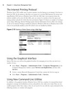
The GUI interface features two panels, one for Products and one for Licenses.These can be
selected by clicking on the appropriate tab within the window. Figure 13.34 illustrates this GUI
panel.
The real blessing of the SecureUpdate tool is that of centralized management and authority.
Using this product, you can apply updates to your Check Point modules in a timelier manner,
update licenses, and modify the currently licensed machines. Before you begin doing this, how-
ever, you should know about a new feature of FireWall-1 NG.This feature is called Central
Licensing and uses what is known as a license repository.
In previous versions of FireWall-1, you had only one licensing option, that of a local license.
Local licensing mandated that the license be tied to the IP address of the module.This model
wasn’t very flexible and made upgrades very difficult and migrations nearly impossible. Central
licensing binds the license to the address of the management server and allows several benefits.
■ When you change the IP address of the firewall module, the license remains useable.
This has not always been the case.
■ All licenses are bound to only one IP address.This allows great flexibility in your FW-1
deployment. Imagine the scenario where your network boundaries are migrated from
one provider to another, and with that comes a new network block. Using central
licensing makes that address change a piece of cake. Licenses can be taken from one
module and given to another and managed from this central location.
Note that while local licenses can still be used with FW-1 NG, you won’t be able to use
them like central licenses.This means that they can’t be detached from their module after they
have been installed.
Before you can begin using the functionality of SecureUpdate product, some common-sense
things have to be in place. Obviously, there needs to be connectivity between the management
module and the modules that are being maintained. For your purposes, connectivity implies both
IP connectivity and FW-1 connectivity (SIC). Once this is all in place, you are on your way to
licensing bliss.
Licenses can be added to the license repository in one of two ways.The first, more tedious
method is to copy the license details by hand.This is annoying and can lead to typographical
errors, (although support exists to paste the license details from the clipboard, obviating the need
www.syngress.com
Figure 13.34 SecureUpdate GUI
252_BDFW_ch13.qxd 9/18/03 5:02 PM Page 522