the best damn firewall book period phần 6 pdf
Bạn đang xem bản rút gọn của tài liệu. Xem và tải ngay bản đầy đủ của tài liệu tại đây (2.26 MB, 133 trang )
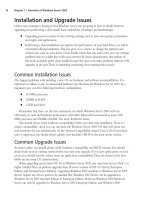
Configuring the Check Point Firewall • Chapter 18 631
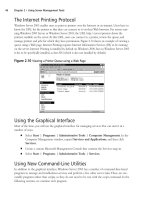
Figure 18.5 Setting Customized Permissions
Permission for LDAP Users Database (Read/[W]rite, [R]ead Only,
[N]one) r
Permission for Security Policy (Read/[W]rite, [R]ead Only,
[N]one) w
Permission for QoS Policy (Read/[W]rite, [R]ead Only, [N]one) n
Permission for Monitoring (Read/[W]rite, [R]ead Only, [N]one) w
Administrator Cherie was added successfully and has
Read Only Permission for SmartUpdate
Read/Write Permission for Check Point Users Database
Read Only Permission for LDAP Users Database
Read/Write Permission for Security Policy
Read/Write Permission for Monitoring
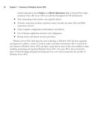
Management Clients
The management clients (also called GUI clients) are installed on either Windows or Solaris (X-
Motif ).These clients can be installed on as many desktops as you like, but before they can con-
nect to the management server, you need to enter their IP addresses into the Management
Clients configuration tool (see Figure 18.6).You can use this feature, for example, if you install
the GUI clients on your own workstation to enable you to control the management server from
your PC.This will allow you to connect remotely to manage the Security Policy and view your
logs and system status.You do not need to configure any clients at all during the install, but if you
are already prepared for this step, you may enter as many clients into this window as necessary.
This client information will be saved in a file on your firewall under $FWDIR/conf and will be
named gui-clients.This is a text file and can be edited directly, or you can bring up this
Management Clients window at any time in the future by running cpconfig.
NOTE
If you have installed an enforcement module only, you will not configure GUI clients.
Figure 18.6 Configuring Management Clients
Configuring Management Clients
=================================
Management clients are trusted hosts from which
Administrators are allowed to log on to this Management Station
using Windows/X-Motif GUI.
No Management clients defined
www.syngress.com
Continued
252_BDFW_18.qxd 9/18/03 5:33 PM Page 631
632 Part IV • Check Point NG and Nokia IP Series Appliances
Figure 18.6 Configuring Management Clients
Do you want to add a Management client (y/n) [y] ?
Please enter the list hosts that will be Management clients.
Enter hostname or IP address, one per line, terminating with CTRL-D or
your EOF character.
192.168.168.3
Is this correct (y/n) [y] ?
As you enter GUI clients into this configuration, you type their host name or IP address, one
per line, pressing Enter at the end of each. When you are done editing the client list, press Ctrl
+ D to send an end-of-file (EOF) control character to the program to continue.
You are allowed to use wildcards in each GUI client host specification as follows:
■
Any If you type in the word Any, you will allow anyone to connect without restric-
tion (not recommended).
■
Asterisks You may use asterisks in the host name, such as 10.10.20.*, which means any
host in the 10.10.20.0/24 network; *.domainname.com means any host name within
the domainname.com domain.
■
Ranges You may use a dash (-) to represent a range of IP addresses, such as 1.1.1.3-
1.1.1.7, which means the five hosts including 1.1.1.3 and 1.1.1.7 and every one in
between.
■
DNS or WINS resolvable hostnames
Figure 18.7 shows an example of the configured GUI clients window with various options
that you can use for your GUI Client entries. We recommend staying away from using host
names or domain names, however, since it requires DNS to be configured and working on the
firewall. Specifying IP addresses is the best method since it doesn’t rely on resolving and will con-
tinue to work even if you cannot reach your DNS name servers from the firewall.
Figure 18.7 Management Client Wildcards
Please enter the list hosts that will be Management clients.
Enter hostname or IP address, one per line, terminating with CTRL-D or
your EOF character.
*.integralis.com
1.1.1.3-1.1.1.7
10.10.10.2
10.10.10.3
10.10.20.*
backwatcher.com
noc.activis.com
Is this correct (y/n) [y] ? y
www.syngress.com
252_BDFW_18.qxd 9/18/03 5:33 PM Page 632
Configuring the Check Point Firewall • Chapter 18 633
Certificate Authority Initialization
Your management server will be a certificate authority (CA) for your firewall enforcement mod-
ules and will use certificates for Secure Internal Communication (SIC).This is the step in the
installation process where the management server’s CA is configured and a certificate is generated
for the server and its components.
You will be presented with the Random Pool configuration option, where you are asked to
input random text until you hear a beep.The timing latency between your key presses will be
used to generate cryptographic data, so it is recommended that you enter the data at a random
pace, so that some keystrokes are close together and others have a longer pause between them.
The more random the key-press intervals, the more unlikely that the input could be duplicated. If
the system determines that the keystrokes are not random enough, it will not take them as input
and will display an asterisk to the right of the progression bar.
NOTE
The Random Pool configuration screen will also be presented to you if you have installed
an enforcement module only so that you can generate an internal certificate for SIC.
Type random characters at random intervals into the Random Pool until the progress bar is
full and the message “Thank you!” appears at the bottom of the window, as shown in Figure
18.8.The next step is to initialize the internal CA for SIC. It could take a minute for the CA to
initialize. Figure 18.9 shows the messages you will receive on the console while configuring the
CA. Press Enter to initialize the CA.
Figure 18.8 Random Pool
Configuring Random Pool
==========================
You are now asked to perform a short random keystroke session.
The random data collected in this session will be used in
various cryptographic operations.
Please enter random text containing at least six different
characters. You will see the '*' symbol after keystrokes that
are too fast or too similar to preceding keystrokes. These
keystrokes will be ignored.
Please keep typing until you hear the beep and the bar is full.
[ ]
Thank you.
www.syngress.com
252_BDFW_18.qxd 9/18/03 5:33 PM Page 633
634 Part IV • Check Point NG and Nokia IP Series Appliances
Figure 18.9 Configuring Certificate Authority
Configuring Certificate Authority
====================================
The system uses an Internal Certificate Authority
to provide Secured Internal Communication (SIC) certificates
for the components in your system.
Note that your components will not be able to communicate
with each other until the Certificate Authority is initialized
and they have their SIC certificate.
Press 'Enter' to initialize the Certificate Authority
Internal Certificate Authority created successfully
Certificate was created successfully
Certificate Authority initialization ended successfully
Once the CA is initialized successfully, you will be prompted to enter and send the FQDN of
the management server to the internal CA (ICA).This name must be correct for the ICA to
function properly and cannot be changed once it is input to the ICA.The following steps can be
used to generate the FQDN shown in Figure 18.10 for this cpconfig setting:
1. Type y and press Enter to define the FQDN now.
2. The current FQDN obtained from the system is displayed. Enter y if you want to
change it.
3. Enter the value of the FQDN (for example, gatekeeper.nokia.com).
4. Enter y if you are sure you typed the value correctly.
5. Now press Enter to send the FQDN to the CA.
Figure 18.10 Sending the FQDN to the ICA
The FQDN (Fully Qualified Domain Name) of this Management Server
is required for proper operation of the Internal Certificate Authority.
Would you like to define it now (y/n) [y] ?
The FQDN of this Management Server is gatekeeper
Do you want to change it (y/n) [n] ?
Warning: The FQDN might be incorrect!
Make sure it contains the host name and the domain name.
www.syngress.com
Continued
252_BDFW_18.qxd 9/18/03 5:33 PM Page 634
Configuring the Check Point Firewall • Chapter 18 635
Figure 18.10 Sending the FQDN to the ICA
NOTE: If the FQDN is incorrect, the Internal CA cannot function properly,
and CRL retrieval will be impossible.
Are you sure gatekeeper is the FQDN of this machine (y/n) [n] ?
Do you want to change it (y/n) [n] ? y
Please enter the FQDN (Fully Qualified Domain Name) of this management:
gatekeeper.nokia.com
Are you sure gatekeeper.nokia.com is the FQDN of this machine (y/n) [n] ? y
Press 'Enter' to send it to the Certificate Authority
Trying to contact CA. It can take up to 4 seconds
FQDN initialized successfully
The FQDN was successfully sent to the CA
Finally, you will be presented with the fingerprint of the management server.This fingerprint
is unique to your CA and the certificate on your server.The first time your GUI clients connect
to the management server, they will receive the fingerprint so that they can match it to the string
listed here and verify that they are connecting to the correct manager. After the first connection,
every time the clients connect to the management server, the fingerprint is verified. If the finger-
prints don’t match, a warning message will be displayed, and the administrator can decide
whether to continue with the connection.This transaction is shown in Figure 18.11.
1. When prompted by cpconfig,“Do you want to save it to a file?” as shown in Figure
18.11, type y and press Enter to save the fingerprint to a file.
2. Type the filename and press Enter.The file will be saved in $CPDIR/conf.
3. Enter y to confirm.
Figure 18.11 Saving the Certificate Fingerprint
Configuring Certificate's Fingerprint
========================================
The following text is the fingerprint of this Management machine:
CARR HOST MEEK FORD ROOM MATH LAIN HOWE BOY SITU SLUM BALM
Do you want to save it to a file? (y/n) [y] ?
Please enter the file name [/opt/CPshared-50-03/conf]: fingerprint.txt
www.syngress.com
Continued
252_BDFW_18.qxd 9/18/03 5:33 PM Page 635
636 Part IV • Check Point NG and Nokia IP Series Appliances
Figure 18.11 Saving the Certificate Fingerprint
The fingerprint will be saved as /opt/CPshared-50-03/conf/fingerprint.txt.
Are you sure? (y/n) [n] ? y
The fingerprint was successfully saved.
Installation Complete
When the configuration program ends, you might see on the screen a few messages such as “gen-
erating GUI-clients INSPECT code” as the system finishes the installation of the VPN-
1/FireWall-1 package. Finally, you will receive the following question:“Would you like to reboot
the machine [y/n]?” (shown in Figure 18.12). If you elect not to reboot, you will exit the instal-
lation and go back to a shell prompt. If you choose to reboot, the system will be restarted imme-
diately.
W
ARNING
If you are remotely connected to this firewall, you will not have access after rebooting.
The firewall loads a policy named InitialPolicy, which prevents all access after an install.
See the sidebar “Unload InitialPolicy Script” for a workaround.
Figure 18.12 Installation Complete
generating GUI-clients INSPECT code
initial_management:
Compiled OK.
Hardening OS Security: Initial policy will be applied
until the first policy is installed
In order to complete the installation
you must reboot the machine.
Do you want to reboot? (y/n) [y] ?
Getting Back to Configuration
Now that installation is complete, you might need to get back into the configuration screens that
you ran through with cpconfig.You can add, modify, or delete any of the previous configuration
settings by running cpconfig at any time from the command line. Each screen that you ran through
during the initial configuration will now be listed as a menu item, as shown in Figure 18.13.
www.syngress.com
252_BDFW_18.qxd 9/18/03 5:33 PM Page 636
Configuring the Check Point Firewall • Chapter 18 637
Figure 18.13 cpconfig
gatekeeper[admin]# cpconfig
This program will let you re-configure
your Check Point products configuration.
Configuration Options:
(1) Licenses
(2) Administrators
(3) Management Clients
(4) SNMP Extension
(5) PKCS#11 Token
(6) Random Pool
(7) Certificate Authority
(8) Automatic start of Check Point Products
(9) Exit
Enter your choice (1-9) :
Three options listed here did not come up during the initial installation process. Option 4
configures the SNMP Extension. By default, the Check Point module’s SNMP daemon is dis-
abled, but if you want to export SNMP MIBS to network monitors, you can use this option to
enable SNMP in FireWall-1. Option 5 in the cpconfig output configures a PKCS#11 token that
allows you to install an add-on card such as an accelerator card; option 8 allows you to configure
the automatic start of Check Point modules at boot time. By default, the Check Point FireWall-1
product will start automatically on reboot.
If you installed an enforcement module only, the cpconfig screens will be a little different.
There will be two new choices:
■
Secure Internal Communication Enables a one-time password that will be used for
authentication between this enforcement module and its management server as well as
any other remote modules that it might communicate with.
■
High Availability Allows you to enable this enforcement module to participate in a
Check Point High Availability (CPHA) configuration with one or more other enforce-
ment modules.This tab will not show up in your installation since you cannot have a
management module installed on an enforcement module in a CPHA cluster.
www.syngress.com
252_BDFW_18.qxd 9/18/03 5:33 PM Page 637
638 Part IV • Check Point NG and Nokia IP Series Appliances
Testing the Configuration
Now that the FireWall-1 package is configured and you have rebooted your Nokia, it’s time to
test access to the firewall so you can configure and install security policies. We want to make sure
that our firewall is installed and configured correctly, and testing the basic administrative firewall
tasks is an easy way to verify that fact.This is particularly important after we have performed an
upgrade between major versions (such as 4.1 to NG). We will test GUI client access as well as
defining and installing a basic policy. For the sake of completeness, we will test both the pushing
and fetching of our security policy.
Testing GUI Client Access
After you have the Check Point packages installed, enabled, and configured, you can begin con-
figuring a security policy for your Nokia firewall. Even if the InitialPolicy is loaded, you should
be able to connect with a GUI client and push a policy. If you have any trouble with this process,
unload the default filter with fw unloadlocal (prior to NG FP2, the command was fw unload local-
host).You can run the management clients on the following operating systems:
■
Windows 98/ME
■
Windows XP (Home or Professional)
■
Windows 2000 SP1 or SP2 (Professional, Server, or Advanced Server)
■
Windows NT SP6a (Workstation or Server)
■
Solaris 8 (32 or 64 bit—note that running the GUI on Solaris requires a Motif license)
If you are running a firewall prior to NG FP3, you will be logging in to the Check Point
Policy Editor to manage security policies. In NG FP3, the name of the editor has been changed
to SmartDashboard.The FP3 SmartDashboard doesn’t look much different from the FP2 interface,
so we will use the FP3 smart clients in our examples. On Windows, begin by going to Start |
Programs | Check Point SMART Clients | SmartDashboard NG FP3.You will be pre-
sented with a login prompt like the one in Figure 18.14.
www.syngress.com
Figure 18.14 SmartDashboard Login
252_BDFW_18.qxd 9/18/03 5:33 PM Page 638
Configuring the Check Point Firewall • Chapter 18 639
To log in the first time, enter your username, password, and management server IP address. If
you are connecting to the Nokia as the management server, enter the IP address of the interface
that is closest to you (it could be the internal IP or SSN IP) in the Management Server box. As
the client connects, you will be presented with the management server’s fingerprint that was gen-
erated during the initial configuration procedure.You should match the fingerprint in the client
to the fingerprint on the management server to verify that you are connecting to the correct
machine (see Figure 18.15). If it matches, click the Approve button to continue logging in to
the management server.
NOTE
In NG FP2 and FP3, you can now select a check box to log in to your management
clients in demo mode. Previously, you would need to log in with the management server
field set to *local to run the demo. Also new in FP3 is the ability to select a management
server from a pull-down list. This is a really nice feature if you normally manage multiple
management servers, since each time you type in a new server, it is added to the list.
If the fingerprint changes because you reinstalled the management server software, put in
new hardware as a replacement for the old management server, or regenerated the ICA certifi-
cate, you will receive a warning similar to the one shown in Figure 18.16. Again, you should
verify the fingerprint before accepting the new one.
www.syngress.com
Figure 18.15 Fingerprint Identification
252_BDFW_18.qxd 9/18/03 5:33 PM Page 639
640 Part IV • Check Point NG and Nokia IP Series Appliances
As long as the fingerprint remains the same, you will get no message after the first accep-
tance. Behind the scenes, Check Point will verify that the fingerprint matches. After you pass
authentication and accept the fingerprint, you will see the SmartDashboard window, as shown in
Figure 18.17. From here you can view and manage your network objects and policies. Initially,
you will have a single object configured to represent your firewall, which NG creates for you
during installation (see Figure 18.18).
www.syngress.com
Figure 18.16 Fingerprint Warning
Figure 18.17 Check Point SmartDashboard
Figure 18.18 Check Point Gateway Object
252_BDFW_18.qxd 9/18/03 5:33 PM Page 640
Configuring the Check Point Firewall • Chapter 18 641
You should verify that your firewall object is configured properly before you try to push a
policy.To edit your firewall object, click Manage in the main menu and select Network
Objects. Highlight the firewall object and click Edit. Check that the correct IP address is
entered in the General Properties tab.The IP entered here should correspond to the external IP
address of your firewall, which is the same IP address that you use for a local license on the fire-
wall. Modify the Check Point products installed to include the options that the installation didn’t
select for you, such as VPN-1, FloodGate-1, and so on. Also verify that the Topology tab is con-
figured with the correct information about your firewall.
NOTE
If you have a distributed installation, you need to create the firewall object for you
Nokia. It will not be created for you as it was in our previous example.
When you are finished editing your firewall object, click OK. Now you can begin creating
all the other network objects that you will need to use in your Security Policy. Using these net-
work objects, you will create a rule base in the Security tab of the SmartDashboard. Here we put
in a simple “accept-all” policy to show you the procedure. Do not use an accept-all policy on
your firewall, since a policy like this will provide you with no protection.
Begin by clicking the Rules menu option and select Add Rule | Top.This will enter the
default rule, any source, destination, or service to drop without logging. Right-click the Action
cell and select Accept.Then, right-click the Track cell and select Log.
Now choose the File menu and Save the policy.The policy is named Standard by default and
is defined in Figure 18.17.
Pushing and Fetching Policy
Now you are ready to test pushing a policy to your Nokia firewall. From the SmartDashboard,
click the Policy menu and choose Install.Your objects, rules, and users will be saved at this time.
If this is the first time you are installing a policy, you will receive a warning message like the one
shown in Figure 18.19 until you click the box to stop showing the message.This message simply
informs you that there are some rules that are defined through the Global Properties that can be
configured through the Policy menu.These rules are “implicit” rules and are not visible in your
Security Policy window.You can make these rules visible by selecting Implied Rules from the
View menu. Check the box so that you don’t see this message again, and click OK to continue.
www.syngress.com
252_BDFW_18.qxd 9/18/03 5:33 PM Page 641
642 Part IV • Check Point NG and Nokia IP Series Appliances
Next you will receive a policy install window where you need to select the type of policy
you will install on certain Check Point objects (see Figure 18.20). If you have multiple firewalls,
they will all be displayed in this window. If you are installing to a stand-alone Nokia, accept the
default values and click OK to begin the installation process. (By stand-alone we mean a VPN-
1/FireWall-1 management server and enforcement module installed on a single platform—in
other words, the opposite of a distributed installation.)
Now your management server will verify the rule base, compile the security policy, and push
the policy to the firewall module. An installation process status window will be displayed, similar
to the one in Figure 18.21. Now you must wait for the installation to complete. When the instal-
lation is done, the Close button will light up and the status will change to a green check mark if
the install was successful.There could be warnings associated with the policy installation, and in
that case a red exclamation point (!) will accompany the check mark, as shown in Figure 18.22.
This installation window is new in NG FP3.
www.syngress.com
Figure 18.19 SmartDashboard Warning
Figure 18.20 Policy Installation Targets
252_BDFW_18.qxd 9/18/03 5:33 PM Page 642
Configuring the Check Point Firewall • Chapter 18 643
If you receive warnings or errors on the installation, you can view these messages by clicking
the button labeled Show Warnings, as shown in Figure 18.22. If you have not yet configured
antispoofing on your gateway’s interfaces, you will always receive these warnings on a policy
install.You could also have a warning about your license, if it will expire in less than a week. See
the errors from the install in Figure 18.23.
www.syngress.com
Figure 18.21 Installation Process
Figure 18.22 Installation Succeeded
Figure 18.23 Verification and Installation Errors
252_BDFW_18.qxd 9/18/03 5:33 PM Page 643
644 Part IV • Check Point NG and Nokia IP Series Appliances
Other status options may be displayed in the Installation Process window. On this page
Check Point provides a Legend button that pops up a quick explanation on each of the possible
status icons you could receive (see Figure 18.24).
If the policy installation was successful, you are done.You can continue to modify and install
your policy as many times as is necessary to completely define a security policy for your organi-
zation. If policy installation fails for some reason, try some of these steps:
■
Verify that the firewall process is running on the module with the command ps –auxw |
grep fw.
■
Try unloading the policy from the console with the command fw unloadlocal, and then
try reinstalling the policy from the management server.
■
Ensure that there is network connectivity between the management server and the
module. Check cables and test with ping.
■
Check that SIC is configured properly. Look at
for assistance.
Once you are set up to push a policy successfully, you will want to verify that the firewall can
fetch a policy from the management station.The Nokia will attempt to fetch a policy on system
startup or whenever the firewall module is restarted.To force the Nokia to fetch a policy, use the
fw fetch command. Available switches for this command are listed in Table 18.3.Type fw fetch
localhost to load the last policy installed, or fw fetch master1 to fetch from the management
host defined as master1 in the $FWDIR/conf/masters file.
Table 18.3 fw fetch Syntax
Switch Description
-n Fetches a policy from the management server and only loads the policy
if it is different from the current policy loaded.
-f <filename> Fetches a policy from the management server listed in <filename>. If
no filename is specified, uses the $FWDIR/conf/masters file.
-i Ignores the SIC information, such as SIC names.
www.syngress.com
Figure 18.24 Status Icon Legend
252_BDFW_18.qxd 9/18/03 5:33 PM Page 644
Configuring the Check Point Firewall • Chapter 18 645
FireWall-1 Command Line
The following are some other useful FireWall-1 commands that you might find handy while
configuring Check Point on your Nokia firewall. Some of these have been discussed throughout
the chapter:
■
cpstop Stops all Check Point products and the SVN Foundation.
■
cpstart Starts the SVN Foundation and all Check Point products.
■
cplic print Prints the currently installed licenses.
■
cplic put Adds a license.
■
fw tab –t connections –s Lists the number of connections in the FireWall-1 connec-
tions table.
■
fw ver Displays the version of VPN-1/FireWall-1. Use the –k switch to see the kernel
version.
■
fw stat Lists the currently loaded policy, date the policy was last installed, and the
interface and direction that the security policy is enforcing.
■
fw unloadlocal Unloads the current security policy so that no policy is loaded.
■
fw load When run on the management console, this can push a policy from command
line to a remote module.
■
fw lichosts Displays the hosts that are protected by your firewall, when a limited
license is installed.
■
fwstop –default Stops all VPN-1/FireWall-1 services and loads the default filter into
the kernel.
■
fwstop –proc Stops all VPN-1/FireWall-1 services, but keeps the policy loaded in the
kernel. Only simple accept, drop, and reject control decisions will be made.
■
fwstart –f Starts the VPN-1/FireWall-1 services.
Upgrading the Firewall
This section is dedicated to upgrading your FireWall-1 software on your NSP. We’ll start by
assuming that you are running FireWall-1 4.1 SP-6 on IPSO 3.4.1 FCS10 or later. If you are on
a prior version of FireWall-1 4.1, you should start by upgrading your IPSO to the latest 3.4.1 and
then upgrading to SP-6. If you are on FireWall-1 4.0, you need to upgrade to 4.1 before
upgrading to NG. Don’t get overzealous; be careful and take small steps, and you will be better
off in the long run.You can upgrade from 4.1 SP-6 to NG FP1, FP2, or FP3. We recommend
that you first go to the FP2 bundle (which actually installs the FP1 packages as well) before
moving on to newer Feature Packs.
The first thing you should do once you are on 4.1 SP-6 is to run your configuration through
one of the upgrade verification tools that Check Point provides.This might catch errors that
could cause the upgrade to fail or cause the resulting configuration to be unusable after the
www.syngress.com
252_BDFW_18.qxd 9/18/03 5:33 PM Page 645
646 Part IV • Check Point NG and Nokia IP Series Appliances
upgrade.There is a tarball named upgrade_verifiers_NG_FP2_nokia.tgz for IPSO 3.4.x and 3.5
and associated release notes.You should only run this on your Nokia if you have a management
server installed.This script checks the $FWDIR/conf directory on your management console.
Download this bundle to your Nokia management server and gunzip and untar it into its own
directory.You can obtain this file from www.checkpoint.com/techsupport/downloadsng/utili-
ties.html#upgrade_verify:
1. If the upgrade_verifiers_NG_FP2_Nokia.tgz file is in your /var/admin directory, create
a subdirectory and put it in there: mkdir upgrade_verifiers; mv upgrade_veri-
fiers_* upgrade_verifiers; cd upgrade_verifiers.
2. Now run gunzip * to uncompress the file.
3. Extract the tarball with the command tar –xvf upgrade*.
4. Run the pre_upgrade_verifier script with the following syntax: pre_upgrade_verifier
–p $FWDIR –c 4.1 –t NG_FP2 –f upgrade.txt.
5. Look in the upgrade.txt file to determine what you might need to change before
beginning the upgrade process.
Remember to read any release notes before you begin the upgrade procedure.You could have
certain configuration options that require special attention before you begin upgrading. Here’s a
brief list of some common configuration issues that you will need to resolve in 4.1 before you
install NG FP2 or later:
■
Disable all FWZ configurations. NG FP2 and later no longer support FWZ for VPNs.
■
Disable objects that have certificates configured for Hybrid IKE.You might even be
better off to delete these objects and recreate them once you’ve upgraded to NG.
■
Disable any SKIP or manual IPSec VPN configurations. Only IKE is supported in NG
FP2 and FP3.
■
Ensure that your firewall object names match exactly the host name of the firewall
modules.This name mapping should be in the hosts file on both the management and
firewall modules as well.You cannot change the host name or object name once you
have upgraded to NG due to the certificates’ dependence on this information.
Upgrading from 4.1 SP6 to NG FP2
If you have a separate management server, always make sure that you upgrade that management
server before you upgrade any firewall modules. Once you are confident that you are ready to
upgrade to NG, download the NG FP2 or FP3 wrapper package to your Nokia and follow the
instructions provided. Here we use the NG FP2 wrapper for demonstration, and we recommend
that you go to FP2 before FP3 to ensure that your configuration is merged successfully at each step.
You can follow this procedure whether your Nokia is a stand-alone or distributed installation:
1. Since you are on IPSO 3.4.1, the first thing you need to do is upgrade your IPSO
image to the latest 3.6 release.
www.syngress.com
252_BDFW_18.qxd 9/18/03 5:33 PM Page 646
Configuring the Check Point Firewall • Chapter 18 647
2. Start now with the wrapper package for NG FP2 named CP_FP2_IPSO.tgz. Ensure
that this is the only package in your /var/admin directory before you begin.Then run
newpkg –i from the /var/admin directory.
3. Press 4 and then press Enter to install from the local file system.
4. When asked to enter a pathname to the package, simply enter a single dot (.) and press
Enter.
5. Now choose 2 and press Enter to upgrade from an old package.
6. Choose the FireWall-1-strong.v4.1.SP-6 - Check Point FireWall-1 (Strong)
Version 4.1 SP-6 (Wed May 15 16:10:58 IDT 2002 Build 41617) package from
the list of packages you can upgrade from. In our list it is number 1, so we choose 1 and
press Enter to continue.
7. Next, the upgrade program will verify that you really want to perform this upgrade
with the following question: “Do you want to upgrade from FireWall-1-strong.v4.1.SP-
6 to CP_FP2_IPSO? [y/n].” Enter y for yes and press Enter to continue. As the pack-
ages are being upgraded and installed, you will receive a lot of messages on the console.
There is no more text for you to input at this time. All you can do is sit patiently and
wait for the upgrade to complete.You will see a message that the WebTheater service is
no longer supported and that it will be deleted.You will also see a notice that the
system failed to find an Internal CA in objects_5_0.C file, but it will be created after
cpstart.You can safely ignore both messages.The following packages are installed while
you wait:
■
NG FP1 SVN Foundation
■
NG FP1 VPN-1/FireWall-1
■
NG FP2 SVN Foundation
■
NG FP2 VPN-1/FireWall-1
■
NG FP2 Backward Compatibility with 4.1 package
■
NG FP2 Policy Server
■
NG FP2 FloodGate-1
■
NG FP2 Real Time Monitor
8. When the newpkg program exits, you will be brought back to a shell prompt. Both the
SVN Foundation and VPN-1/FireWall-1 packages are already enabled in Voyager.You
need to log out and log back in to the Nokia to obtain the latest environment variables.
So, type exit and then log in again.
9. Run cpconfig. If you need help with any of the options here, read the section on
cpconfig earlier in this chapter.You need to add a new license because 4.1 licenses will
not function on NG.
www.syngress.com
252_BDFW_18.qxd 9/18/03 5:33 PM Page 647
648 Part IV • Check Point NG and Nokia IP Series Appliances
10. Reboot. When the system comes back up it will not load the last policy you had
installed in 4.1. It will load the defaultfilter policy instead.You need to push the policy
to the firewall the first time after the upgrade.
11. Log into your management server from your NG FP2 Policy Editor Management
Client. Accept the fingerprint and verify that your policy appears to be intact after the
upgrade.
12. Select Install from the Policy menu to push a policy.
13. Test communication through your firewall.You might need to reconstruct VPN settings
and set up Hybrid IKE again to get things working the way they were prior to the
upgrade.
NOTE
If you receive a verification error that says “Missing IP protocol for user defined service
MSExchange-DirectoryRef,” simply delete this service from the Manage | Services
window and restart the installation.
If you upgraded from 4.1 directly to FP3, you might need to configure interfaces in
the Topology tab on your Check Point Gateway object before you can install a policy.
Upgrading from NG FP2 to NG FP3
The upgrade procedure for FP3 is very simple.You begin as you did with the FP2 upgrade—by
downloading the FP3 wrapper package called CP_FP3_IPSO.tgz.You can run this wrapper to
upgrade from 4.1 SP-6, NG FP1, or NG FP2 or to install NG FP3 from scratch on your Nokia
firewall. We took you through the procedure of a fresh install at the beginning of the chapter.To
upgrade to FP3 instead, run newpkg –i as you normally do to install a new package, but when
prompted whether to install or upgrade, select 2 and press Enter to upgrade from an old
package.
After upgrading to FP3, the FP3 SVN Foundation and VPN-1/FireWall-1 packages will
already be enabled in Voyager. All you need to do is exit your login session and log back in to
obtain the correct environment variables. Run cpconfig and if there is nothing new to configure,
exit cpconfig and reboot. When the system comes back up, the InitialPolicy will be loaded,
which means that you need to push a policy after the upgrade.
Backing Out from NG to 4.1
If you need to back out from a recent upgrade for some reason, the procedure on a Nokia is quite
simple. First, you need to disable any NG components such as Policy Server and FloodGate-1 and
Apply and Save your changes. Next, disable NG VPN-1/FireWall-1 and Apply and Save, and
then finally disable the NG SVN Foundation package and Apply and Save.
Now you can enable the old 4.1 package and Apply and Save your changes.Then you must
reboot the box. When the box comes back up, the FireWall-1 services will not be started.You
www.syngress.com
252_BDFW_18.qxd 9/18/03 5:33 PM Page 648
Configuring the Check Point Firewall • Chapter 18 649
must log in to Voyager and go to the Check Point FireWall-1 configuration screen found
under the Security and Access Configuration heading. Click the option button next to Start
FireWall-1 automatically at reboot? to On, then Apply and Save. Finally, log in to the
Nokia and run fwstart from the command line.The firewall will load the last 4.1 policy you had
configured, pick up where you left off before the upgrade, and start automatically on the next
reboot.You can go back into Voyager and delete any disabled packages for cleanup if you don’t
want to save them for another try later.
www.syngress.com
252_BDFW_18.qxd 9/18/03 5:33 PM Page 649
650 Chapter 18 • Configuring the Check Point Firewall
Summary
All FireWall-1 administrators with Nokia firewalls need to know basic tasks such as installing and
upgrading the Check Point FireWall-1 software packages. If you never upgraded your firewall,
you could be at risk if there are known vulnerabilities in that release that have been resolved in
newer patches. In this chapter we provided the tools necessary to complete these tasks so that you
can continue to secure your organization with Check Point FireWall-1 on Nokia.
Preparation is always key to a successful upgrade or install. With FireWall-1, you need to
obtain licenses, configure a hosts entry, and possibly upgrade the IPSO image on your Nokia
before you can begin with Check Point. It’s also very important to read all release notes available
before you install new software.
Once you have the software installed on IPSO, you then need to enable it. If you are running
Check Point NG, you will first need to enable the SVN Foundation, Apply and Save your con-
figuration, and then enable the VPN-1/FireWall-1 packages. When you enable packages through
the Manage Installed Packages configuration screen, the file /var/etc/pm_profile is updated with
appropriate environment variables.This means that you will have to log in again to the Nokia
after the packages are enabled to receive the correct shell environment.The next step to config-
uring the firewall is to run cpconfig.The first run of this utility will prompt you for the type of
install (stand-alone or distributed), licenses, administrators, management clients, ICA initialization,
SIC password (firewall module only), and then finally to reboot.You can always reconfigure your
firewall at any time by running cpconfig again, which will provide you with a menu to choose
the option you want to edit.
After configuring Check Point, you need to verify that you can log in with the management
clients and push a policy.You should also test fetching a policy to ensure that the firewall will
operate properly during a reboot. If you have any problem doing these things, verify that the fire-
wall is running on the module with the command ps –auxw | grep fw, try unloading the
policy from the console with the command fw unloadlocal, ensure that there is connectivity
between the management server and the module by checking cables and testing with ping, and
check that SIC is configured properly.
Once you have a running FireWall-1 installation, you eventually need to upgrade your fire-
wall software to stay up to date. Whenever you are upgrading the firewall in IPSO, you must first
upgrade your IPSO image to one compatible with the new software.The next step is to get the
new firewall package downloaded to your Nokia, and then run newpkg –i to start the upgrade.
Choose the option to upgrade from an old version (as opposed to install, which will not copy
over your configuration), and then choose the old FireWall-1 package that you are upgrading
from. If you’re upgrading from 4.1 to NG, run your configuration through an upgrade verifier
utility provided by Check Point to see if there are any configuration issues that you can sort out
before you upgrade the management server.The recommended upgrade path is to go from 4.1
SP-6 to NG FP2 via the wrapper package (which installs FP1 first) and then to NG FP3.
www.syngress.com
252_BDFW_18.qxd 9/18/03 5:33 PM Page 650
Introducing the
Voyager Web
Interface
Solutions in this chapter:
■ Basic System Configuration, Out of
the Box
■ Configuring the System for Security
■ Understanding Configuration Options
Chapter 19
651
252_BDFW_ch19.qxd 9/18/03 5:34 PM Page 651
652 Part IV • Check Point NG and Nokia IP Series Appliances
Introduction
Administrators tasked with installing a firewall for the first time typically have to be very knowl-
edgeable when it comes to configuring the underlying operating system to function efficiently as
a firewalled router.The administrator must know how to configure interface IP addresses and
speed/duplex settings, how to configure hostnames and Domain Name Service (DNS) properly,
and how to configure static or dynamic routing, among many other things.
We have seen that the IPSO operating system that is at the core of the Nokia appliances is
UNIX-based, but we don’t need to have in-depth knowledge of UNIX to go through a first-
time or even repeat configuration.The Nokia Voyager allows us to configure all of the previously
mentioned features and much, much more through a simple, Web-based interface.The vast
majority of changes we make do not require a system reboot, but take effect immediately
(another helpful side-effect of IPSO’s UNIX base).
In this chapter, we walk you through a very thorough initial configuration of your Nokia
appliance, all done from within Voyager.The emphasis is on security, so when we talk about net-
work access and services, we show you how to, for example, disable Telnet access and enable SSL
for secure Web access through Voyager. We give you an alternative to FTP or show you how to
make FTP more secure, if it must be used. We also go over each of the Voyager configuration
options so that when you are done you will have a very good idea of just what can be accom-
plished with this powerful interface.
Basic System Configuration, Out of the Box
Once the initial system is configured, your Nokia runs a minimal installation of Apache Web
server, and the server runs on the standard port 80 by default. IPSO 3.3 through IPSO 3.6 FCS3
use Apache/1.3.6.You can view the Apache version on your Nokia by running the command
/bin/httpd –v.This server is running for the purpose of serving out the Web pages necessary for
you to configure your Nokia Security Platform (NSP) using the Nokia Voyager Web interface.
You always have the option of running the Voyager interface using the lynx text browser
through a console connection, but once you have assigned an IP address to your Nokia, you will
be able to connect with any Web browser on the network to configure the system.Although
Lynx is a useful tool, many administrators prefer the nicer Voyager GUI available through a
graphical Web browser.
NOTE
Remember to save your configuration changes using the Save icon within your Voyager
GUI if you want to save any changes you make to the system. At every configuration
screen in the Voyager interface, you will see icons at the top and bottom of each page
that give you the options to go Home, Up, To p, Apply, or Save. After every change that
you apply to the system, the change takes effect immediately, but you must select Save
to write your changes to the /config/active file if you want changes you make to be pre-
served through a reboot of the system.
www.syngress.com
252_BDFW_ch19.qxd 9/18/03 5:34 PM Page 652
Introducing the Voyager Web Interface • Chapter 19 653
Front Screen
When you went through the initial configuration, you set up your internal interface with the
Nokia. Now you can begin configuring your appliance by typing in the IP address of this inter-
face in a Web browser such as http://10.10.10.10 or using a DNS-resolvable name instead of an
IP address, if available. Next enter the admin username and password when prompted for authen-
tication.This step brings you to the front screen of the Voyager interface, which should resemble
the image in Figure 19.1.
You should notice that some very important system information is listed on this initial screen,
such as the Nokia’s model, software release, and version, as well as the serial number, which you’ll
need when you call in a support or maintenance request.The information on this front screen is
the same regardless of the Nokia model you possess.To continue from this initial screen, select
Config, to enter the main configuration screen (see Figure 19.2).This screen gives you all the
possible options for configuring your NSP. In versions previous to IPSO 3.6, this screen looks
slightly different, but most of the options are the same. From the initial screen, select Monitor to
enter a read-only area, which allows you to view system status and other interesting information
about the system.
Navigating Voyager
When you are moving around within the Voyager interface, it is important that you do not use
your browser’s Back button to return to a previous screen. If you do this, you could end up get-
ting cached pages that display incorrect information, which can cause confusion and possible mis-
www.syngress.com
Figure 19.1 The Voyager Front Screen Display
Figure 19.2 The Main Configuration Screen
252_BDFW_ch19.qxd 9/18/03 5:34 PM Page 653
654 Part IV • Check Point NG and Nokia IP Series Appliances
configuration. Instead, use the buttons that are provided for navigation across the top and bottom
of each screen.These buttons and each of their functions are as follows:
■ Home Displays the front screen.
■ To p Displays the main Configuration screen or main Monitor screen, depending on
which you are working under.
■ Up Displays the previous page.
■ Apply Applies changes entered on that page.
■ Save Saves all changes that have been applied to the system, since either the last save or
the last reboot.
■ Help Displays help documentation relevant to the current page.
You will also see several small help buttons available throughout the various screens.You can
identify these by the blue, circular icon with a white H displayed in the center. Each one gives
you detailed help information for each section in which the button is displayed.This help feature
pops up in a separate browser window, so you don’t lose your current place within the Voyager
interface.
If you installed the documentation package available for your version of IPSO, a Doc button
is available along with the other navigation buttons on each page.This documentation provides
even more help for each section of the configuration. In IPSO 3.6, there is even a CLI Reference
Guide to assist you in using the new Command Line Interface Shell (CLISH) tool. In the docu-
mentation, select the Content button at any time to see a list of available topics.
Configuring Basic Interface Information
When configuring interfaces, you should know what IP address and netmask you will assign each
interface in advance. For the examples that follow in this chapter, let’s assume that you have a
simple Nokia firewall with three interfaces: external (Internet facing, routable IP), internal (non-
routable IP), and SSN (nonroutable IP). Assume an upstream router owned by the ISP that pro-
vides the Internet circuit as your default gateway.
In this section, we walk you through the process of configuring an Ethernet interface on
your NSP.You will learn how to add or delete an IP address to an interface, manually set the
speed and duplex, and check the status of your interfaces.
IP Addresses
When setting up the internal and secure server network (SSN or DMZ) interfaces, you should
choose a network subnet within the Internet Assigned Numbers Authority (IANA) reserved IP
address space, which are outlined in RFC 1918.
Adding an IP Address to an Interface
Follow these steps to configure an interface on your Nokia platform:
1. Bring up the Voyager Web interface via http in your Web browser.
2. Click Config.
www.syngress.com
252_BDFW_ch19.qxd 9/18/03 5:34 PM Page 654
Introducing the Voyager Web Interface • Chapter 19 655
3. Click Interfaces, the first link in the first column under the main Configuration screen.
You will see the Interface Configuration page displayed as in Figure 19.3.This table shows
you all your available interfaces along with their current status and configuration options.
4. Select the logical interface to which you will assign an IP address. In our example, we’ll
select eth-s4p1c0, the second Ethernet interface listed in the table in Figure 19.3.
5. Click the toggle button to On to make the interface active, and type in the new IP
address and mask length in your browser. All netmasks configured through Voyager will
be in aggregate or bit mask format. For example, 255.255.0.0 is a 16-bit mask, so to set
that mask on an interface, you would type 16 for the mask length.There is a good net-
mask cheat sheet at which might help you
convert a netmask in dotted quad notation to the aggregate, and vice versa. Or, if you
have Check Point Next Generation Security Administration by Syngress Publishing, Inc.
(ISBN 1-928994-74-1), you’ll find a cheat sheet in Appendix A.
6. Optionally, you can change the logical name of the interface from the default eth-
s4p1c0 to a name that might make it easier to identify, such as either internal or
external.The default name of the interface might not be easy to read, but it helps you
identify the interface you are configuring on the Nokia. For example, eth-s4p1c0 is the
Ethernet interface in slot 4, port 1.These numbers vary depending on how many inter-
faces you have installed and which you are configuring. See Figure 19.4 for an example
interface configuration before you go on to the next step.
7. Click Apply. Once you apply your changes, they take effect immediately.
www.syngress.com
Figure 19.3 The Interface Configuration Screen
Figure 19.4 Configuring IP Addresses
252_BDFW_ch19.qxd 9/18/03 5:34 PM Page 655