the best damn firewall book period phần 7 docx
Bạn đang xem bản rút gọn của tài liệu. Xem và tải ngay bản đầy đủ của tài liệu tại đây (2 MB, 133 trang )
764 Part IV • Check Point NG and Nokia IP Series Appliances
|qfe2|192.168.12.131|Up | 0| 0| 0|
|qfe3| 192.168.1.131|Down | 32000| 0| 0|
Problem Notification table
|Name |Status|Priority|Verified|Descr|
|Synchronization|OK | 0| 1618| |
|Filter |OK | 0| 1618| |
|cphad |OK | 0| 0| |
|fwd |OK | 0| 0| |
fw1 #
From this output, we can see that there is a problem with the local member (fw1 in this
example) and that the status of interface qfe3 is down.
How ClusterXL Works in Load-Sharing Mode
ClusterXL in Load-Sharing mode works in a very similar way to ClusterXL in HA New mode
but with the following unique distinctions:
■
The MAC address used for the VIP address is shared among cluster members for that
subnet.This means that there is no MAC address change on failure of a member as far
as the network equipment on the local subnet of the cluster is concerned.
■
The MAC address of the VIP address is a multicast MAC address. (in other words, its
first octet is an odd number).
■
In a healthy load-sharing cluster, all members of the cluster should be active and routing
a portion of the active traffic.
Connections through the cluster are managed on a per-connection basis. For example, if a
host on 192.168.1.200 initiates a connection through the cluster to 195.166.16.129 and member
fw1 takes the connection, the connection will just go through member fw1 unless a failure of
member fw1 occurs.The connection will continue through member fw1 until the session has
completed. No asymmetric routing should occur on this particular connection.
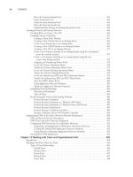
The member in the cluster a new connection will go through is based on a hash of specific
parameters defined in the Advanced section for ClusterXL Load Sharing (see Figure 21.49).
www.syngress.com
252_BDFW_21.qxd 9/18/03 5:48 PM Page 764
High Availability and Clustering • Chapter 21 765
Assuming a “normal” connection passing through the cluster, all the packets involved will
have the same hash value. For an Internet firewall, this means that, for a particular connection, a
packet arriving from the internal network and a packet arriving from the Internet will have the
same hash value. However, if the cluster is performing NAT or if VPNs are involved, we have a
potential problem.The IP addresses and ports will be different on the “inside” and “outside” of
the firewall. FireWall-1’s stateful inspection helps us out here; because it understands what
changes have been applied to connections, it can adjust the hashing accordingly.
As with ClusterXL in HA New mode, the members of the cluster still have their real IP
addresses bound to their interfaces.This is particularly useful when the SmartCenter server is
communicating with the cluster members, because it need not be located on the secured net-
work.This makes it easier for the SmartCenter server to manage other firewall modules as well as
the cluster.
Although all members are live and handling traffic, who should respond to ARP requests for
the VIP address? The members in the ClusterXL cluster will agree on which member in the
cluster will respond to the ARP request; however, that choice is not based on the member pri-
ority in the cluster, and even if a member is designated as having a problem but the interfaces on
the member are active, the problem member may still respond to the ARP request. Within the
ARP reply packets is the multicast MAC address for the VIP.
NOTE
You need to make sure that adjacent hosts and routers will accept a multicast MAC reply
for a nonmulticast IP address. For example, host 192.168.1.200 would ARP for
192.168.1.130—the VIP address of the cluster—in order to route packets through the
cluster. The ARP response would contain a multicast MAC address. Different systems
respond in different ways: Windows is generally fine, but Cisco routers on the same
subnet will not accept the ARP reply and will not cache the multicast MAC address, so
steps need to be taken to circumvent this problem for Cisco routers. These steps usually
involve entering a static entry into the ARP table of the router for the multicast MAC
address.
ClusterXL Load-Sharing Mode Failover
As with ClusterXL in HA New mode, the key to how failover works is in the CPHA protocol
that the members send to all the other members in the cluster, using multicasts.
www.syngress.com
Figure 21.49 A Load-Sharing Algorithm Hash Can Be Based on These Parameters
252_BDFW_21.qxd 9/18/03 5:48 PM Page 765
766 Part IV • Check Point NG and Nokia IP Series Appliances
There are many similarities between ClusterXL HA New mode and ClusterXL Load-Sharing
mode CPHA protocol packets. In fact, they are identical in the way they work, apart from some
details in the UDP data payload.The similarities include:
■
The source MAC address of the CPHA update packet is always 00:00:00:00:fe:<member
number>, where member 1 would be 00, member 2 would be 01, and so on.
■
The destination MAC is always a multicast MAC address, ending with the VIP address
in the last two octets of the MAC address.
■
The source IP of the CPHA update packet is always 0.0.0.0.
■
The destination IP address of the CPHA update packet is always the network IP
address.
■
Layer 4 (the transport layer of the OSI model) is always UDP, source port 8116, destina-
tion port 8116.
■
The first part of the CPHA payload within the UDP header packet is the same as
ClusterXL in HA New mode, and the format of an FW_HA_MYSTATE payload is the
same parameters but different data for these parameters.
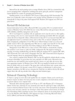
If we focus on the last point, we can see from Figure 21.50 how the data for the same param-
eters differ.
The main areas of note here are the HA mode, which states that the mode is mode 4
FWHA_Balance_mode—more than one member active. ClusterXL in HA New mode is referred
to as mode 2 in this field.
The other field of note is “Machine states.”This field communicates what the member origi-
nating the CPHA packet thinks the status of all the other members is. As we can see in Figure
21.50, the sending member is aware that member 0 is active.This packet was originated from
member 1, or fw2 from our example.
www.syngress.com
Figure 21.50 Packet Structure of a CPHA Packet When a Cluster Is in Load-Sharing Mode
252_BDFW_21.qxd 9/18/03 5:48 PM Page 766
High Availability and Clustering • Chapter 21 767
Under normal operation, these CPHA packets are multicast to all the other members in the
cluster. Each member multicasts its perception of the state of the rest of the members in the
cluster.This process occurs on each interface of a cluster member and is sent at regular intervals,
several a second.
Examining the CPHA protocol between cluster members, we see that if there is a problem
on the member, the other members will show a “Machine states” value for that the member as
down/dead.The member that is taking over a particular connection will then ARP for the MAC
address of the local host it needs to push a packet to, and on response, it will continue the session.
Note that the hosts on the local subnet do not notice any change in MAC address or IP address
on failover.You could notice a small glitch in the data transfer while the failure occurs and
failover to another member takes place, but the period of disruption should always be less than
three seconds and is usually just over one second.
Note that when a member in a load-sharing cluster takes over from another member, there is
no gratuitous ARP broadcast, unlike HA mode.This is because it is unnecessary since there has
been no MAC address change.
Special Considerations for
ClusterXL in Load-Sharing Mode
We have covered the principles of how ClusterXL in Load-Sharing mode works. We now con-
trast and compare how the special considerations for ClusterXL in Load-Sharing mode differ rel-
ative to other cluster modes.
Network Address Translation
ClusterXL in Load-Sharing mode is actually quite forgiving with regard to NAT and how proxy
ARP is performed, unlike HA mode. It will handle manual proxy ARP entries fine for NATed IP
addresses, as long as you proxy ARP for the cluster multicast MAC address.You enter these static
published ARP entries on all members in the cluster. Automatic ARP configuration can be
selected in the Policy | Global Properties | Network Address Translation area of the
SmartDashboard GUI.This works fine because the multicast MAC address is used for all the
automatic ARPs that are required. Manual routes on the ISP router can also be used instead of
using proxy ARPs.
To summarize, as long as the multicast MAC address is used in any manual proxy ARPs, there
should be no issues with Load-Sharing mode and NAT.
User Authentication and One-Time Passcodes
Like all HA and Load-Sharing clustering solutions, if you are using the Check Point security
servers (for SMTP, HTTP, or FTP services) and a failover occurs, you will lose the connection
and have to start again through the new member that the traffic is now going through.The secu-
rity server and remote authentication issues discussed earlier in this chapter (comparing single
gateway and clustering functionality) apply particularly to Load-Sharing mode, because sessions—
with multiple connections—are always likely to be shared between all cluster members, unlike
HA, when problems only occur on failover.
www.syngress.com
252_BDFW_21.qxd 9/18/03 5:48 PM Page 767
768 Part IV • Check Point NG and Nokia IP Series Appliances
Nokia IPSO Clustering
ClusterXL is not available for the Nokia platform.This is because Nokia provides its own HA
and load-sharing solutions. In this section, we look at the load-sharing cluster solution that Nokia
provides on IPSO 3.6-FCS4, how to configure it, and how to configure FireWall-1 NG FP3 so
that you have a complete Nokia load-sharing solution. We then talk about how you can test the
cluster and go over any special considerations for this solution.
Nokia Configuration
To configure a Nokia load-sharing cluster, you need to take the following steps:
1. Configure the interfaces of a Nokia.
2. Configure FireWall-1.
3. Configure clustering in Voyager.
We assume that you have installed IPSO 3.6 FCS-4 on your Nokia and that you have the
Check Point FireWall-1 NG FP3 package installed and configured. As with setting up all clusters,
it is recommended that you complete and test the physical connectivity first so that any problems
that you encounter later aren’t due to a misconfigured switch or interface, because these could be
difficult to spot later.
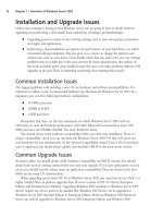
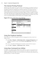
In our example shown in Figure 21.51, you can see a sample Nokia cluster topology.
www.syngress.com
Figure 21.51 Our Example Nokia Clustering Topology Setup
fw1
fw2
Hub
Hub
Hub
Hub
ISP Router
cpmgr
PDC
192.168.11.131
eth-s1p2c0
MAC=00:c0:95:e0:15:dd
192.168.11.132
eth-s2p2c0
MAC=00:c0:95:e2:b1:41
195.166.16.134
195.166.16.131
eth-s1p1c0
MAC=00:c0:95:e0:15:dc
195.166.16.132
eth-s2p1c0
MAC=00:c0:95:e2:b1:40
192.168.1.131
eth-s1p4c0
MAC=00:c0:95:e0:15:df
192.168.1.132
eth-s2p4c0
MAC=00:c0:95:e2:b1:43
195.166.12.131
eth-s1p3c0
MAC=00:c0:95:e0:15:de
192.168.12.132
eth-s2p3c0
MAC=00:c0:95:e2:b1:42
192.168.1.200
Default route =
192.168.1.130
Out to the Internet
195.166.16.129
State sync Network
192.168.11.0 /24
External Network
195.166.16.0/24
VIP = 195.166.16.130
VMAC=01:50:5a:a6:10:82
Cluster control Network
192.168.12.0/24
VIP = 192.168.12.130
VMAC=1:50:5a:a8:c:82
Internal Network
192.168.1.0/24
VIP = 192.168.1.130
VMAC=01:50:5a:a8:01:82
Domain = london.com
252_BDFW_21.qxd 9/18/03 5:48 PM Page 768
High Availability and Clustering • Chapter 21 769
The main difference in network topology between Nokia clustering and using Check Point
ClusterXL is that you require a dedicated network for Nokia cluster control communications.
This is in addition to the Check Point state sync network.
As you can see from Figure 21.51, each network that has a VIP also has a virtual MAC
address—a multicast MAC that is used for the VIP. From a network perspective of neighboring
equipment on the same network as the cluster interfaces, it looks very similar to Check Point
ClusterXL in Load-Sharing mode.
You should ensure that you have configured all of the following using Voyager on each of the
cluster members:
■
Make sure that interface speeds are consistent across host and switches on the subnet.
Only use full-duplex where connected directly to full-duplex-enabled switches!
■
Make sure you have entries in each hosts file for the FireWall-1 management station and
the other modules in the cluster.
■
Make sure you have the correct time and date and the correct default local for each
member in the cluster and on the Check Point management station.
■
Make sure that the FireWall-1 NG FP3 package is installed.
■
Read the Nokia IPSO and Check Point NG FP3 release notes!
A Few Points about Installing an
Initial Configuration of NG FP3 on Nokia IPSO
Installing software packages on the Nokia platform is very different compared to installing on
other platforms. Packages are added to Nokia and “enabled” using the Voyager interface.
However, that is not the end of the process of installing FireWall-1 NG FP3.You need to log out
after the package install and run the cpconfig command on the Nokia console.The output you will
see is fairly similar to the output you would see in the UNIX installation of a cluster, and the
choices you would make are identical.
One section during the install is specific to clustering:
Would you like to install a Check Point clustering product (CPHA, CPLS or
State Synchronization)? (y/n) [n] ? y
Even though you will be using the Nokia clustering solution, make sure you answer y.This
will make sure that you have the state synchronization available when you set up your cluster.
That is essential for ensuring that connections continue through another member when failover
occurs.
Check Point FireWall-1 Configuration for a Nokia Cluster
We will run through the most direct method of configuring FireWall-1 objects and rules for a
Nokia cluster.This means that we will create the cluster member objects via the gateway cluster
object directly and set up the SIC trusts between the management station and the cluster mem-
bers within the cluster gateway object. Once the cluster gateway object is configured, we will
www.syngress.com
252_BDFW_21.qxd 9/18/03 5:48 PM Page 769
770 Part IV • Check Point NG and Nokia IP Series Appliances
install a basic policy to the cluster. If you have not already done so, it’s a good idea to look
through the “Configuring FireWall-1 for ClusterXL in HA New Mode” configuration procedure
described earlier in this chapter, because there are many similarities.
Configuring the Gateway Cluster Object
Within the NG FP3 SmartDashboard GUI, click Manage | Network Objects and click the
New button. Select Check Point | Gateway Cluster.You will be presented with a pop-up
window (see Figure 21.52).
Particular areas of note here are that the IP address stated in the General tab is the external
interface.The other important points to note are that the ClusterXL check box is unchecked.
Now click the Cluster Members menu option on the left side of this screen. Run through
the steps for creating a new member, as we did when configuring Cluster XL HA New mode.
After the trust has been set up between the management module and enforcement module,
click the Topology tab and click Get Topology. For each interface that is received, click it and
set the topology for it. For example, the eth-s1p1c0 interface has IP address 195.166.16.131
assigned to it, and this is marked as our External interface in the topology. All the others are
defined as This Network (see Figure 21.53).
www.syngress.com
Figure 21.52 Defining General Properties of the Nokia Cluster
252_BDFW_21.qxd 9/18/03 5:48 PM Page 770
High Availability and Clustering • Chapter 21 771
Click OK.You should now have the first member of the cluster defined and trusted. Repeat
the procedure again in the Cluster Members menu to add the second cluster (and third, fourth,
and so on). Use the New button each time. Once complete, you should have a list of cluster
members defined.
Click Availability Mode on the left side of the screen to select which mode the Nokia
cluster will operate in. Make sure you select Load Sharing (see Figure 21.54). Note that in
Nokia clustering, this setting has no functional effect, but it is useful to select the correct one so
that when you look at it again, you know what mode you are operating your Nokia cluster in! It
is also useful to avoid any confusion if you need to seek technical support.
www.syngress.com
Figure 21.53 Topology of a Cluster Member
Figure 21.54 Availability Mode Configuration for a Nokia Cluster
252_BDFW_21.qxd 9/18/03 5:48 PM Page 771
772 Part IV • Check Point NG and Nokia IP Series Appliances
Click the Synchronization menu option on the left side of the screen.You need to add the
network you are going to use for synchronizing the FireWall-1 state tables. Note that this net-
work should not be the same as your Nokia cluster control network.
Click the Add button to add a synchronization network. In our example, the IP address is
192.168.11.0 , and the netmask is 255.255.255.0. (See step 8 and Figure 21.23 of “Configuring
ClusterXL in HA New Mode” for an example.) Click OK.
It is possible to add backup synchronization networks here; it would be acceptable to include
the Nokia control network as a backup sync network, but if you do, the cluster should be moni-
tored carefully so that a failover to this network is quickly identified and addressed.
Configuring topology in the cluster object when using Nokia clustering is not mandatory—
in fact, it is not recommended. Doing so will change the behavior of the cluster with regard to
packets originating from a member in the cluster.The effect of configuring a topology is covered
in “Special Considerations for Nokia Clusters” later in this chapter.
Once this process is complete, you are ready to click OK and start defining your security
policy.
Configuring the Nokia Cluster Rule Base
You have some choices as to the rule base you want to install.You can either see if the configura-
tion of your cluster object is going to work and install an open policy, or you can create a strict
policy now. Remember, there is still one more step to do, which is to configure the clustering on
Nokia using Voyager.This being the case, you might want to install an open policy now and then
tighten it later once you are happy that your clustering is working correctly.
You need to allow IPSO cluster control protocols between each IP address of the Nokia
cluster.This means you will have a rule, close to the top of your rule base, that will look some-
thing like Figure 21.55.
The group fwcluster-clusterips is made up of node host objects, one for each VIP address
(195.166.16.130, 192.168.12.130, and 192.168.1.130 in our example).
WARNING
It is vital to add the fwcluster-clusterips group to security policy rules wherever you use
the cluster object as a destination. This is because the cluster object does not include the
VIP addresses, since we have not defined the cluster topology information. However, it is
possible to connect to the VIP addresses. This is most important when defining the
“stealth” rule (see Figure 21.57).
www.syngress.com
Figure 21.55 Rule Showing Communication between Cluster Members
252_BDFW_21.qxd 9/18/03 5:48 PM Page 772
High Availability and Clustering • Chapter 21 773
The ipso-cc group is made up of two services that we will call IPSO Cluster Control Protocol
1 and IPSO Cluster Control Protocol 2.You define these by clicking Manage | Services |
New | TCP.The definition of these services is shown in Figures 6.56 and 6.57, respectively.
Once defined, these services can be added to a service group (defined as ipso-cc in our
example).
In addition to the ipso-cc services, we have also accepted the Network Time Protocol (NTP).
Running NTP is a good idea to make sure that the time between the Nokia cluster members
does not drift.
When you define the “stealth” rule in order to explicitly protect the cluster members, add the
cluster object and the group of VIPs, fwcluster-clusterips, as shown in Figure 21.58.
Once you have configured your policy, install it to the cluster object. Note that in Figure
21.59, we can see that the policy will fail to install if it does not install to all members of the
cluster. One thing to be acutely aware of here is that if a member in the cluster is down or
switched off and later comes online and becomes functional, it will first look at other members
www.syngress.com
Figure 21.56 Defining Service for IPSO Cluster Control Protocol 1
Figure 21.57 Defining Service for IPSO Cluster Control Protocol 2
Figure 21.58 A Stealth Rule on a Nokia Cluster Rule Base
252_BDFW_21.qxd 9/18/03 5:48 PM Page 773
774 Part IV • Check Point NG and Nokia IP Series Appliances
of the cluster to compare the policy that it has against the policy that the other cluster members
have. If the other cluster members have a more recent policy, the cluster member that has just
come up will download the policy from one of the other cluster members—before it attempts to
download the policy from the management module.
Once you have installed a policy, you have to complete the last step in configuring a Nokia
load-sharing cluster: configuring the clustering on the Nokia appliances themselves.
Nokia Cluster Configuration on Voyager
When we configured the Gateway Cluster object in the SmartDashboard GUI, we did not con-
figure the gateway cluster to have ClusterXL installed.This feature is not available on the Nokia
platform; Nokia provides its own solution for load sharing. However, you have to configure it
within the Voyager interface.
Note that you have to configure the cluster on each Nokia in the cluster, so you will have to
repeat the procedure of configuring the cluster on each Nokia.This might sound obvious, but it
is often something that is forgotten!
Voyager Configuration
Make sure that you have network connectivity from your browser to your Nokia FireWall-1
modules in your cluster, and make sure that the security policy you have installed on the Nokia
appliances does not prevent you from accessing Voyager from your browser. Navigate to Voyager
on the first member in your cluster. In our example, we do this by going to
https://195.166.16.131 (see Figure 21.60).
www.syngress.com
Figure 21.59 Installing the Security Policy for the Cluster
252_BDFW_21.qxd 9/18/03 5:48 PM Page 774
High Availability and Clustering • Chapter 21 775
Here are the steps you need to follow after you have authenticated and are presented with
the main screen:
1. From the main Voyager screen, click Traffic Management Configuration.
2. Click Cluster.The new screen will look something like Figure 21.61.
3. Enter a cluster ID.This can be any decimal number between 0 and 65,535. For sim-
plicity, we chose 130 for our example. Once you’ve entered an ID, click Apply and
then Save.
4. The cluster configuration screen will then expand to include more parameters that can
be configured within the cluster.
5. The bottom half of the screen presented in Figure 21.62 is shown in Figure 21.63; it
shows how to configure the clustering for member fw1 in our example.
www.syngress.com
Figure 21.60 Voyager’s Main Screen
Figure 21.61 The Initial Cluster Configuration Screen
252_BDFW_21.qxd 9/18/03 5:48 PM Page 775
776 Part IV • Check Point NG and Nokia IP Series Appliances
6. Set up your cluster information. Note that the sync interface, eth-s1p2c0, has parameter
No for the Select column and the Hash Selection column has None.The external inter-
face eth-s1p1c0 has the hash algorithm NAT_EXT selected, and the internal interface
eth-s1p4c0 has NAT_INT selected.The Cluster Control network has the Primary
Interface option button checked, and the hash selection is set to default.
7. Decide if you are going to use SecuRemote Clients and select yes or no. If you scroll
further down the screen, you will see a section for defining VPN tunnel information.
This is where you enter the remote encryption domain and remote gateway IP address
so that this information is taken into account when the load-sharing algorithm is calcu-
lated.This ensures that the same member of the cluster participates in the VPN connec-
tion (as asymmetric routing would cause the VPN to fail).
WARNING
UDP encapsulation for secure remote connections is not taken into account for the
Nokia IPSO cluster load-sharing algorithm, so it will therefore fail.
www.syngress.com
Figure 21.62 Uninitialized Cluster in Voyager
Figure 21.63 Cluster Configuration for the First Cluster Member
252_BDFW_21.qxd 9/18/03 5:48 PM Page 776
High Availability and Clustering • Chapter 21 777
8. Make sure that you click Apply and Save to save the changes you have made.
9. You can now make the cluster active, even with just one member. Click the Cluster
State Up option button, and then click Apply and Save, as shown in Figure 21.64.
Once it is up and running, your cluster should route traffic through member fw1, if
adjacent hosts are using the VIP address of the local subnet that they are connected to as
their default gateway.
10. This completes member fw1 in the cluster configuration.You now need to point your
browser to the second member and configure it to complement your configuration of
member fw1. Note that the settings have to be correct and you have to use the equiva-
lent interfaces on fw2 as fw1 and that the hashing algorithm you select must be iden-
tical to member fw1. When you change the Cluster State to Up, Voyager will inform
you that the fw2 member is joining the cluster.This could take a little while (see Figure
21.65) and you will be informed as to whether the procedure succeeds or fails.
11. If joining the cluster is successful, the member will announce that it is now a member of
the cluster (see Figure 21.66). Both members of the cluster are now up and running,
and you are ready to test your Nokia cluster.
www.syngress.com
Figure 21.64 Bringing Up the First Cluster Member
Figure 21.65 Member fw2 Joining the Cluster
252_BDFW_21.qxd 9/18/03 5:48 PM Page 777
778 Part IV • Check Point NG and Nokia IP Series Appliances
Testing the Nokia Cluster
Once your Nokia cluster is set up, you need to test it to make sure that it is functioning cor-
rectly.Again, you need to keep in mind the way that this particular clustering technology works
and how it differs from the other clustering solutions we have covered so far.
Test 1: Pinging the Virtual IP Address of Each Interface
With Nokia clustering in load sharing, you should be able to ping the local VIP address of the
cluster with a host that is on the same subnet as the cluster interfaces.You will receive a response
if everything is working properly.
In the test we ran on our example network, a ping was initiated from the FireWall-1 manage-
ment station (195.166.16.134) to the VIP of the cluster (195.166.16.130). A packet trace was run
at the same time on the management station to analyze the packet for the ping session. If you
look at the ARP cache of the local host initiating the ping, you should now have the multicast
MAC address of the VIP. In our case, this is 01:50:5a:a6:10:82 (which you can check against
Figure 21.51).This in itself does not tell you much—just that the VIP address is up and running
and that a member in the cluster responded. But can we tell which member?
The answer is yes, we can, but only if we examine the packet trace we took when the ping
session took place. If we look at the reply packet, in the data link layer, we can see the real MAC
address of the member that responded, as shown in the packet analysis in Figure 21.67.
www.syngress.com
Figure 21.66 Second Member of a Nokia Cluster Is Now Online
Figure 21.67 Analyzing the ICMP Echo Reply for the Source MAC Address
252_BDFW_21.qxd 9/18/03 5:48 PM Page 778
High Availability and Clustering • Chapter 21 779
In our example, we can see that the source MAC is 00:0c:95:e2:b1:40, which corresponds
with member fw2 in the cluster (see Figure 21.51). Note that even though the real MAC address
of the fw2 member was used, the source IP address for the ICMP echo reply was the virtual IP
of 195.166.16.130.
Test 2: Determining the Status of Each Member in the Cluster
In a Nokia cluster, there are two tools you can use to monitor the status of the cluster and its
members. One is the SmartView Status GUI, and the other is using Voyager monitoring.
The SmartView Status GUI shows you the health of each member and if it is in state table
sync with other members of the cluster. What it won’t show you is the correct status of each
interface of each member. For this information, you have to use the Nokia Voyager screens on
each member in the cluster.
Notice that in Figure 21.68, all the interfaces seem to be up; however, they would report this
status even if one of the interfaces was unplugged.The giveaway that SmartView Status cannot
monitor the interfaces is that the “Working mode” field says Sync only. This means that the only
function ClusterXL is performing on a Nokia cluster is state table synchronization.
Checking the monitoring of the cluster through Voyager is straightforward. Connect your
browser to one of the members, select the Monitor button, and then click Cluster Monitor.This
will show you the main statistics of each member in the cluster (see Figure 21.69) from the point of
view of the member you are connected to. If everything is working correctly, it should not matter
which member you connect to with Voyager, because they should all report the same status.
www.syngress.com
Figure 21.68 SmartView Status Does Not Show an Accurate Interface Status
252_BDFW_21.qxd 9/18/03 5:48 PM Page 779
780 Part IV • Check Point NG and Nokia IP Series Appliances
If a member in the cluster fails, you will see it removed from the cluster members table. If
you only have one member left after a member fails (if you have a two-member cluster), the
remaining member will also become master.Take note of the Time Since Join parameter in the
cluster members table. This parameter tells you how long a particular member has been online.
One other place not to be forgotten when you’re checking the health of your Nokia cluster
is the system logs.These can be located in the /var/log/messages file.You should see entries from
the clusterd process, which shows the status of the cluster.
In Figure 21.70, you can see a sample message of what will be seen in the /var/adm/message
file when the internal Ethernet interface cable is removed from one of the members of the
cluster, and then restored. Note that when this happens, you will also see the cluster members
table show one fewer member in the cluster (see Figure 21.71).
Figure 21.70 Sample of Nokia /var/log/messages After Internal Interface Was Removed,
Then Restored
Jan 27 07:29:35 fw1 [LOG_NOTICE] clusterd[251]: Member(192.168.12.132)
member id (2) left cluster(130):
Jan 27 07:30:15 fw1 [LOG_NOTICE] clusterd[251]: New member(192.168.12.132)
joined cluster(130) with member id(2).
www.syngress.com
Figure 21.69 Both Members Are Online as Part of the Cluster
252_BDFW_21.qxd 9/18/03 5:48 PM Page 780
High Availability and Clustering • Chapter 21 781
Test 3: FTPing through a Load-Sharing
Nokia Cluster During Interface Failure
Like ClusterXL load sharing and HA New mode, the best test you can perform is a real-world
test. In load sharing, a simple test consists of starting a connection through the cluster and moni-
toring the cluster to determine which member the connection has gone through. If the test con-
nection is the only connection, you might be able to see this from the “Work assigned” value in
the cluster monitoring facility in Voyager, or you could use the FireWall-1 NG FP3 SmartView
Tracker (with a hotfix applied to show origin IP addresses of the member in the cluster), or you
could use SmartView Monitor.
In this example, we have started an FTP session through the cluster, and we are using
SmartView Monitor to monitor the traffic through the cluster. When we initiate the FTP session
through the cluster and start downloading data, we can see that all the load is on member fw2 in
the cluster (see Figure 21.72).
www.syngress.com
Figure 21.71 One Member Only in Cluster
Figure 21.72 Display of Traffic through SmartView Monitor
252_BDFW_21.qxd 9/18/03 5:49 PM Page 781
782 Part IV • Check Point NG and Nokia IP Series Appliances
As we can see in Figure 21.72, the FTP session was started at 11:52:30, and failure occurred
at 11:52:48 (actually, we pulled the internal interface connector out of member fw2). Figure
21.73 shows that member fw1 took over the session.
Note that the timeline shows that member fw1 did not take over the load for three seconds.
Command-Line Stats
We saw earlier that ClusterXL uses the cphaprob command to determine status of the cluster. We
can use a similar Nokia command-line tool to check the status of a Nokia cluster.
On the Nokia platform, we use the Command Line Interface Shell (known as clish).This is
an interactive command line, although a single command can be executed using the –c “com-
mand” option. Once in the shell, you can use the command show clusters to determine the status
of the members in the cluster (see Figure 21.74).
Figure 21.74 Example of Use of the clish Command to Check the Cluster Status
fw2[admin]# clish
Nokia> show clusters
CID 130
Cluster State up
Member ID 1
Protocol State master
System Uptime At Join 1:02:58:57
Performance Rating 275
Failure Interval 4000
www.syngress.com
Figure 21.73 Display of Traffic through Member fw1 When fw2 Fails
252_BDFW_21.qxd 9/18/03 5:49 PM Page 782
High Availability and Clustering • Chapter 21 783
Figure 21.74 Example of Use of the clish Command to Check the Cluster Status
Cold Start Delay 30
Number of Interfaces 3
Primary Interface eth-s2p3c0
Interface eth-s2p1c0
IP Address 195.166.16.132/24
Cluster IP Address 195.166.16.130
Hash NAT-external
Interface eth-s2p3c0
IP Address 192.168.12.132/24
Cluster IP Address 192.168.12.130
Hash default
Interface eth-s2p4c0
IP Address 192.168.1.132/24
Cluster IP Address 192.168.1.130
Hash NAT-internal
Member(s) information
Number of Member(s) 2
Member 1 (master)
IP Address 192.168.12.132
HostName(Platform) fw2(IP400)
OS Release 3.6-FCS4
Rating 275
Time Since Join 0:19:20:57
Cluster Uptime At Join 0:00:00:00
Work Assigned 50%
Member 2 (member)
IP Address 192.168.12.131
HostName(Platform) fw1(IP400)
OS Release 3.6-FCS4
Rating 275
Time Since Join 0:19:14:34
Cluster Uptime At Join 0:00:06:22
Work Assigned 50%
Nokia> show cluster securemote
yes
Nokia> show cluster vpn-tunnels
www.syngress.com
252_BDFW_21.qxd 9/18/03 5:49 PM Page 783
784 Part IV • Check Point NG and Nokia IP Series Appliances
Figure 21.74 Example of Use of the clish Command to Check the Cluster Status
VPN tunnel(s) configured
Network/Mask Destination
192.168.254.0/24 194.155.13.33
Nokia> exit
Goodbye
Many commands are variations of the show cluster command. See the Nokia Command Line
Reference Guide for further information.You can use the cphaprob command on the Nokia platform
if you like, but the information that it will tell you is limited. For example, it can’t tell you which
interfaces are up or down. It can tell you if the state table synchronization is working or not.
How Nokia Clustering Works
Nokia clustering has many similarities to the Check Point ClusterXL load-sharing solution, but
because the clustering is not part of the Check Point product, you do get some differences that
are significant. We can draw some parallels between ClusterXL load sharing and Nokia clustering
as follows:
■
Both ClusterXL load sharing and Nokia clustering use a VIP address and a multicast
MAC address, so devices on the local subnet do not see any difference when initiating
connections through the cluster. On a Nokia cluster, there is always a host that is
assigned master in the cluster, and this member will respond to ARP requests.
■
Both ClusterXL and Nokia clustering have a method for each member to tell the other
members its status in the cluster. However, the ways that they do this are different.
ClusterXL does this using the CPHA protocol, which is sent from each interface of the
cluster member to all other cluster members. Nokia uses a dedicated network to com-
municate using its own protocols: IP protocol 0x90 (144 decimal), which is a multicast
MAC destination and IP address, and two TCP services (ports 11003 and 11004). Note
that the protocol 0x90 traffic bypasses the firewall, so no policy rules are required.
■
Both systems have a load-sharing hashing method that can be altered by the user. On
Nokia, this method is set up in Voyager, based on whether your interface is external or
internal (or a VPN gateway); on Check Point ClusterXL, this is based on three choices:
IP addresses, ports, and SPI (VPN negotiation); IP addresses and ports; or just IP
addresses.
■
Like ClusterXL, connections through the Nokia cluster are directed through one
member in the cluster on a per-connection basis. Asymmetric routing is avoided by the
load-sharing algorithm, and although this would still work if it does occur, you could
get some sessions dropped when they initiate, due to the reply being received from the
remote host before the state tables have an opportunity to synchronize between the
cluster members.
www.syngress.com
252_BDFW_21.qxd 9/18/03 5:49 PM Page 784
High Availability and Clustering • Chapter 21 785
■
Just like ClusterXL, the Nokia members still have valid IP addresses that you can con-
nect to.
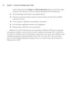
Let’s walk through an example of how a connection would work through a Nokia cluster. In
our example, host 192.168.1.200 will initiate a Telnet session through the Nokia cluster to our
ISP router on IP address 195.166.16.129, and as before, in our ClusterXL HA New mode, we
will hide the connection behind the cluster external IP address of 195.166.16.130, using a hide
rule in our firewall NAT rule base.
When the Telnet session is initiated, the host 192.168.1.200 sends out an ARP request for
192.168.1.130, which is the default gateway on the network 192.168.1.0.The response in the
ARP will be a multicast MAC address—a MAC address that applies to all members of our cluster
for the internal interface.The Nokia member that is the master will always send the ARP
response. (More on the master later.) In our example, the MAC address returned is
01:50:5a:a8:01:82. Our host on 192.168.1.200 then sends a SYN TCP packet, high source port,
destination is to 195.166.16.129, destination MAC is 01:50:5a:a8:01:82 (the default gateway
MAC address).
All members in the cluster will receive this packet, but only one of them will do anything
with the packet—depending on which member in the cluster is meant to pick up the packet,
which is based on the load-sharing algorithm.The member who will deal with the connection
will pass the packet up through the IP stack to the Check Point FireWall-1 NG FP3 kernel for
the incoming interface.The TCP SYN packet will pass through the rule base of the firewall and,
providing everything is fine, it will then send the packet out of its external interface, with the
source IP address of 195.166.16.130 (the external cluster IP address), with the source MAC
address of the member that is taking the connection (in our example, the source MAC address is
00:c0:95:e2:b1:40, which corresponds with member fw2 external interface eth-s2p1c0), and the
destination IP address will be 195.166.16.129 (see Figure 21.75).
www.syngress.com
Figure 21.75 Description of a Connection through a Nokia Load-Sharing Cluster
fw1
fw2
Hub
Hub
Hub
ISP Router
cpmgr
PDC
192.168.11.131
eth-s1p2c0
MAC=00:c0:95:e0:15:dd
192.168.11.132
eth-s2p2c0
MAC=00:c0:95:e2:b1:41
195.166.16.134
195.166.16.131
eth-s1p1c0
MAC=00:c0:95:e0:15:dc
195.166.16.132
eth-s2p1c0
MAC=00:c0:95:e2:b1:40
192.168.1.131
eth-s1p4c0
MAC=00:c0:95:e0:15:df
192.168.1.132
eth-s2p4c0
MAC=00:c0:95:e2:b1:43
192.168.1.200
Default route =
192.168.1.130
Out to the Internet
195.166.16.129
State sync Network
192.168.11.0 /24
External Network
195.166.16.0/24
VIP = 195.166.16.130
VMAC=01:50:5a:a6:10:82
Internal Network
192.168.1.0/24
VIP = 192.168.1.130
VMAC=01:50:5a:a8:01:82
Domain = london.com
1. TCP SYN
packet sent to
multicast MAC
2. Load sharing hash
calculates that fw2
should take the
connection
3. Packet is HIDE address
translated behind VIP
4. SYN ACK packet
is sent to multicast
MAC 01:50:5a:a6:10:82
5. Reply packet is
accpepted by fw2
based on hashing
algorithm, and address
translated.
252_BDFW_21.qxd 9/18/03 5:49 PM Page 785
786 Part IV • Check Point NG and Nokia IP Series Appliances
If the Telnet daemon is listening when the packet reaches the ISP router on 195.166.16.129,
it will produce a response. Again, the ISP router will issue an ARP request for IP address
195.166.16.130, which is the VIP of the cluster.The master member will respond to the ARP
request, sending the multicast MAC address as the MAC address associated with IP
195.166.16.130 (but it will keep the source MAC address of the ARP reply as its own physical
external interface; this is one way to see which of your Nokia members is the master without
using Voyager). Host 195.166.16.130 will then send a SYN,ACK TCP packet, the source IP will
be 195.166.16.129, source port will be 23, and the destination MAC will be the multicast MAC
address of the VIP 195,166.16.130, which is 01:50:5a:a6:10:82 in our example.
Again, the reply packet gets onto all members in the cluster, and the correct member that
took the original SYN packet for the connection is selected by the hashing algorithm that was
selected for that interface.
N
OTE
It is important to understand the importance and meaning of the various hashing algo-
rithms. The reply packets get sent back through the same member based on which
hashing algorithms you select. For example, if you use Hide NAT when initiating a con-
nection that leaves through the external interface, you have to pick hashing methods
that take the NAT into account: NAT_EXT for the external interface, NAT_INT for the
internal interface. Not doing this could cause the reply packets to be accepted by the
wrong member in the cluster by the load-sharing algorithm, ending up with asymmetric
routing. In some complex NAT configurations, there will be conflicts as to which hashing
algorithms should be used—for example, where “double NAT” takes place. If these con-
figurations cannot be avoided, other measures should be taken to avoid asynchronous
routing, such as static routing via members. This could well lead to imbalances in load
sharing and lack of resilience for some connections.
The packet then leaves the internal interface of member fw2 in our example; the source IP is
the 195.166.16.129 IP address of the ISP router, the source MAC address is the internal interface
MAC address 00:c0:95:e2:b1:43 of fw2, and the destination IP is now 192.168.1.200 (it has been
address translated by FireWall-1).
Nokia Cluster Failover
In the event of a failure condition, network traffic taken by that member needs to be routed by
an alternative member in the cluster.This is done on the cluster control network.Again, the key
is the cluster control protocol that uses this network.
The Nokia cluster control protocol is used by the member that is the master.The master
member sends out the status of the cluster to all other members in the cluster, using the cluster
control protocol.The master member is usually the first member that is made active when you
create a Nokia cluster. If the master fails, another member will take over and become master.
There is only one master member in any cluster, but the member that is master can change
depending on failures in the cluster.
www.syngress.com
252_BDFW_21.qxd 9/18/03 5:49 PM Page 786
High Availability and Clustering • Chapter 21 787
When the master member in the cluster communicates with the other members in the
cluster, it uses the Nokia cluster control protocol, which is IP protocol 0x90 (144 decimal).The
cluster control network is used exclusively (unlike the CPHA protocol used in ClusterXL). When
the master communicates with the other members in the cluster, it is from the real source MAC
address of the master on the control network, the source is the real IP address of the master, the
destination MAC address is a multicast MAC address, and the IP address is a multicast IP address.
For example, if member fw1 were the master, it would send out a packet, source MAC
00:c0:95:e0:15:de, source IP 192.168.12.131, destination MAC 01:00:5e:00:01:90, destination IP
address 224.0.1.144.All members that receive the packet will often respond, with their real source
MAC and IP address, to the real destination MAC and IP address of the master.
In our example, if member fw1 were the master and member fw1 failed, fw2 would be the
master.You would notice that fw2 would start to issue IP protocol 0x90 packets from its real IP,
and the destination IP would be the multicast IP for the other members in the cluster.This is
another method you can use to determine which member in the Nokia cluster thinks it is the
master. Note that when a new master is chosen, it will stay the master until it fails and cannot be
the master any longer.You will also see TCP ports 11003 and 11004 Nokia cluster control con-
nections on the cluster control network.
Failover from the point of view of the networking devices on the same local subnet as the
VIPs is transparent because the MAC address used by the cluster does not change.There will be a
short delay during failover as the load-sharing algorithm determines which member in the cluster
will take over the connections of the failed member.This process can take up to four seconds.
Nokia Failover Conditions
Failure of a Nokia cluster member is determined when one of the following occurs:
■
IP forwarding fails or is stopped (for example, by cpstop).
■
The FireWall-1 process fwd dies.
■
An interface goes down.
All these scenarios are monitored by the clusterd process on each Nokia member. When a
failover occurs, the clusterd process logs the event in the Nokia system logs (/var/log/messages file).
Special Considerations for Nokia Clusters
We have talked a little about how the Nokia clustering solution works, so based on how the
technology in Nokia clustering works, we need to take into account its effects when setting up
our cluster and the rule base we are likely to use.
Network Address Translation
As with all clusters, the way you decide to implement your NAT rules needs to be taken into
account. In ClusterXL in HA New mode, we noticed that you cannot use manual proxy ARP
entries into the OS. In ClusterXL in Load-Sharing mode, we stated that all methods of NAT and
proxy ARP should work fine.
www.syngress.com
252_BDFW_21.qxd 9/18/03 5:49 PM Page 787
788 Part IV • Check Point NG and Nokia IP Series Appliances
In a Nokia cluster, you cannot use Check Point’s own Automatic ARP setting in the Policy
| Global Properties | NAT – Network Address Translation | Automatic Rules for
Automatic ARP Configuration menu.
The reason for this is that each member will proxy ARP for the real MAC address of the
member in the cluster as opposed to proxy ARPing the multicast MAC address of the cluster. For
this reason, you cannot use Automatic ARP Configuration.
You can enter proxy ARP entries into Voyager for NATed IP addresses, using the multicast
MAC address of the cluster interface.You can also use static routes on the ISP router to route
traffic to the VIP address of the cluster for the NATed IP address.
If you plan to use proxy ARPs for multicast MAC addresses on the Nokia platform, you need
to enable Accept Multicast reply to ARP on the ARP page of the Voyager interface.You
need to do this for all members that make up your cluster.
N
OTE
Accept Multicast reply to ARP must be enabled for the cluster to work properly.
Defining the Cluster Object Topology
When defining the gateway cluster object for the Nokia cluster, it is possible to define the cluster
topology, listing the VIPs. However, this apparently harmless change results in a significant change
in FireWall-1 behavior. Connections that originate from individual cluster members are subject to
implicit Hide NAT behind the outgoing cluster VIP.This will affect traffic such as DNS lookups
and outgoing FTP connections originating from cluster members.This is the same behavior we
saw under ClusterXL. As with ClusterXL, once FP3 Hot Fix 1 is applied, packets routed back to
the wrong member will be routed onward via the sync link. Check Point ClusterXL makes
allowances for this when handling this traffic, dealing with it gracefully. A Nokia clustering solu-
tion will not deal with it as well, and the traffic involved will not be reliable.This behavior will
also cause a problem with traffic between external interfaces of members. For these reasons,
defining the cluster topology is not recommended when you’re using a Nokia solution. Possibly
this configuration will be made workable in future releases of NG.
Nokia IPSO VRRP Clusters
If a simple HA cluster solution is required for the Nokia platform, a VRRP configuration should
be considered. In this section, we provide an overview of the VRRP protocol, how to configure
it on IPSO, and how to configure FireWall-1 NG FP3 for a VRRP cluster. We’ll then talk about
how you can test the cluster and go over any special considerations that you need to keep in
mind when using a cluster.
Nokia Configuration
To configure a Nokia VRRP cluster, you need to take the following steps:
www.syngress.com
252_BDFW_21.qxd 9/18/03 5:49 PM Page 788