Beginning AutoCAD 2002 Episode 1 docx
Bạn đang xem bản rút gọn của tài liệu. Xem và tải ngay bản đầy đủ của tài liệu tại đây (670 KB, 24 trang )
Beginning
AutoCAD 2002
AutoCAD2002_prelims 14/06/2002 19:02 Page i
Other titles from Bob McFarlane
Beginning AutoCAD ISBN 0 340 58571 4
Progressing with AutoCAD ISBN 0 340 60173 6
Introducing 3D AutoCAD ISBN 0 340 61456 0
Solid Modelling with AutoCAD ISBN 0 340 63204 6
Assignments in AutoCAD ISBN 0 340 69181 6
Starting with AutoCAD LT ISBN 0 340 62543 0
Advancing with AutoCAD LT ISBN 0 340 64579 2
3D Draughting using AutoCAD ISBN 0 340 67782 1
Beginning AutoCAD R13 for Windows ISBN 0 340 64572 5
Advancing with AutoCAD R13 for Windows ISBN 0 340 69187 5
Modelling with AutoCAD R13 for Windows ISBN 0 340 69251 0
Using AutoLISP with AutoCAD ISBN 0 340 72016 6
Beginning AutoCAD R14 for Windows NT and Windows 95 ISBN 0 340 72017 4
Advancing with AutoCAD R14 for Windows NT and Windows 95 ISBN 0 340 74053 1
Modelling with AutoCAD R14 for Windows NT and Windows 95 ISBN 0 340 73161 3
An Introduction to AEC 5.1 with AutoCAD R14 ISBN 0 340 74185 6
AutoCAD2002_prelims 17/06/2002 15:16 Page ii
Beginning
AutoCAD 2002
Bob McFarlane
MSc, BSc, ARCST,
CEng, FIED, RCADDes
MIMechE, MIEE, MIMgt, MBCS, MCSD
Curriculum Manager CAD and New Media, Motherwell College,
Autodesk Educational Developer
OXFORD AMSTERDAM BOSTON LONDON NEW YORK PARIS
SAN DIEGO SAN FRANCISCO SINGAPORE SYDNEY TOKYO
AutoCAD2002_prelims 14/06/2002 19:02 Page iii
Butterworth-Heinemann
An imprint of Elsevier Science
Linacre House, Jordan Hill, Oxford OX2 8DP
225 Wildwood Avenue, Woburn, MA 01801-2041
First published 2002
Copyright © 2002, R. McFarlane. All rights reserved
The right of Bob McFarlane to be identified as the author of this work has
been asserted in accordance with the Copyright, Designs and Patents Act 1988.
No part of this publication may be reproduced in any material form (including
photocopying or storing in any medium by electronic means and whether or
not transiently or incidentally to some other use of this publication) without
the written permission of the copyright holder except in accordance with the
provisions of the Copyright, Designs and Patents Act 1988 or under the terms
of a licence issued by the Copyright Licensing Agency Ltd, 90 Tottenham
Court Road, London, England W1T 4LP. Applications for the copyright
holder’s written permission to reproduce any part of this publication
should be addressed to the publisher
British Library Cataloguing in Publication Data
A catalogue record for this book is available from the British Library
Library of Congress Cataloguing in Publication Data
A catalogue record for this book is available from the Library of Congress
ISBN 0 7506 5610 7
Produced and typeset by Gray Publishing, Tunbridge Wells, Kent
Printed and bound in Great Britain by Bath Press, Avon
For information on all Butterworth-Heinemann
publications visit our website at www.bh.com
AutoCAD2002_prelims 14/06/2002 19:02 Page iv
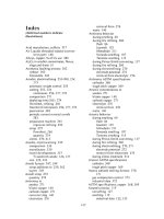
Contents
Preface vii
Chapter 1 What’s new in AutoCAD 2002 1
Chapter 2 System requirements and installation 3
Chapter 3 Using the book 5
Chapter 4 AutoCAD 2002 graphics screen 6
Chapter 5 Drawing, erasing and the selection set 19
Chapter 6 The 2D drawing aids 30
Chapter 7 Saving and opening drawings 35
Chapter 8 Standard sheet 1 42
Chapter 9 Line creation and coordinate entry 44
Chapter 10 Circle creation 52
Chapter 11 Object snap 56
Chapter 12 Arc, donut and ellipse creation 66
Chapter 13 Layers and standard sheet 2 71
Chapter 14 User exercise 1 85
Chapter 15 Fillet and chamfer 87
Chapter 16 Offset, extend, trim and change commands 92
Chapter 17 User exercise 2 102
Chapter 18 Text 104
Chapter 19 Dimensioning 111
Chapter 20 Dimension styles 1 118
Chapter 21 Modifying objects 129
Chapter 22 Grips 141
Chapter 23 Drawing assistance 148
Chapter 24 Viewing a drawing 154
Chapter 25 Hatching 160
Chapter 26 Point, polygon and solid 175
AutoCAD2002_prelims 14/06/2002 19:02 Page v
Chapter 27 Polylines and splines 180
Chapter 28 Modifying polylines and splines 189
Chapter 29 Divide, measure and break 196
Chapter 30 Lengthen, align and stretch 199
Chapter 31 Obtaining information from a drawing 205
Chapter 32 Text fonts and styles 211
Chapter 33 Multiline text 218
Chapter 34 The ARRAY command 226
Chapter 35 Changing properties 234
Chapter 36 User exercise 3 243
Chapter 37 Dimension styles 2 245
Chapter 38 Drawing with different sizes 258
Chapter 39 Multilines, complex lines and groups 264
Chapter 40 Blocks 272
Chapter 41 WBLOCKS 286
Chapter 42 Attributes 294
Chapter 43 External references 301
Chapter 44 Isometric drawings 305
Chapter 45 Model space and paper space 310
Chapter 46 Templates and standards 323
Chapter 47 The AutoCAD Design Center 336
Chapter 48 The TODAY window 347
Chapter 49 ‘Electronic’ AutoCAD 354
Activities 366
Index 385
vi Beginning AutoCAD 2002
AutoCAD2002_prelims 14/06/2002 19:02 Page vi
To: Stephen and Amanda.
Many congratulations on your marriage,
from Mum, Dad, Lynda and Ciara.
AutoCAD2002_prelims 14/06/2002 19:02 Page viii
Enhanced features
AutoCAD Today
Allows the user to manage drawing and template files, load symbol libraries, access the
Bulletin Board for collaborative work and access the AutoDESK Point A design portal.
Live Object Enablers
Increases the value of designs and reduces time between drawing and data sharing.
Publish to Web
The user can the Publish to Web wizard with template, themes and I-drop options.
Many (but not all) of these new features will be discussed in this book.
2 Beginning AutoCAD 2002
Beginning with AutoCAD 2002.qxd 14/06/2002 19:03 Page 2
Optional hardware
• Open GL-compatible 3D video card
• Printer or plotter
• Digitizer
• Modem or access to an Internet connection
• Network interface card.
The installation procedure should follow the instructions given in the AutoCAD 2002
Users’ Manual.
4 Beginning AutoCAD 2002
Beginning with AutoCAD 2002.qxd 14/06/2002 19:03 Page 4
The graphics screen
The AutoCAD 2002 graphics screen (Fig. 4.2) displays the following:
1 The title bar 9 The coordinate system icon
2 The ‘windows buttons’ 10 The drawing area
3 The menu bar 11 The on-screen cursor
4 The Standard toolbar 12 The grips and/or pickfirst box
5 The Object Properties toolbar 13 Scroll bars
6 The Windows taskbar 14 The Layout tabs
7 The Status bar 15 The Modify toolbar
8 The Command prompt window area 16 The Draw toolbar.
The AutoCAD 2002 graphics screen 7
Figure 4.2 The AutoCAD 2002 graphics screen.
Beginning with AutoCAD 2002.qxd 14/06/2002 19:03 Page 7
Title bar
The title bar is positioned at the top of the screen and displays the AutoCAD 2002 icon,
the AutoCAD Release version and the current drawing name.
The Windows buttons
The Windows buttons are positioned to the right of the title bar, and are:
a) left button: minimise screen
b) centre button: maximise screen
c) right button: close current application.
The menu bar
The menu bar displays the default AutoCAD menu headings. By moving the mouse into
the menu bar area, the cursor cross-hairs change to a pick arrow and with a left-click
on any heading, the relevant ‘pull-down’ menu will be displayed. The full menu bar
headings are:
File Edit View Insert Format Tools Draw Dimension Modify Image Windows Help
Figure 4.3 displays the full menu pull-down selections for a sample of menu bar
headings, i.e. File, Format, Draw and Modify.
8 Beginning AutoCAD 2002
Figure 4.3 The pull-down menus from four menu bar selections.
Beginning with AutoCAD 2002.qxd 14/06/2002 19:03 Page 8
Menu bar notes
1 Pull-down menu items which display ‘…’ result in a screen dialogue box when the item
is selected, i.e. left-clicked
2 Pull-down menu items which display ᭤ result in a further menu when selected. This is
termed the cascade menu effect.
3 Menu items in BOLD type are available for selection.
4 Menu items in GREY type are not available for selection.
5 Menu bar and pull-down menu items can be selected (picked) with the mouse or by
using the Alt key with the letter which is underlined, e.g.
a) Alt with M, activates the Modify pull-down menu
b) then Alt with Y, activates the Copy command.
6 Certain items can be activated using the control (Ctrl) key with a letter or number. The
most common items are:
a) Ctrl with N – New drawing
b) Ctrl with O – Open drawing
c) Ctrl with S – Save drawing
d) Ctrl with P – Plot drawing
e) Ctrl with 1 – Properties dialogue box.
7 In this book, items will be generally selected from the menu bar with the mouse.
The Standard toolbar
The Standard toolbar is normally positioned below the menu bar and allows the user
access to 30 button icon selections including New, Open, Save, Print, etc. By moving the
cursor pick arrow onto an icon and ‘leaving it for about a second’, the icon name will
be displayed in yellow (default). The standard toolbar can be positioned anywhere on
the screen or ‘turned off’ if required by the user.
The Object Properties toolbar
Normally positioned below the Standard toolbar, this allows a further seven button icon
selections. The icons in this toolbar are Make Object’s Layer Current, Layers, Layer
Control, Layer Previous, Color Control, Linetype control and Lineweight Control.
The Windows taskbar
This is at the bottom of the screen and displays:
a) the Windows ‘Start button’ and icon
b) the name of any application which has been opened, e.g. AutoCAD
c) the time and the sound control icon
d) perhaps some other icons depending on the user’s system.
By left-clicking on ‘Start’, the user has access to the other Programs which can be run
‘on top of AutoCAD’, i.e. multi-tasking.
The Status bar
Positioned above the Windows taskbar, the status bar gives useful information to the
user:
a) on-screen cursor X, Y and Z coordinates at the left
b) drawing aid buttons, e.g. SNAP, GRID, ORTHO, POLAR, OSNAP, OTRACK, LWT
c) MODEL/PAPER space toggle
The AutoCAD 2002 graphics screen 9
Beginning with AutoCAD 2002.qxd 14/06/2002 19:03 Page 9
Command prompt window area
The command prompt area is where the user ‘communicates’ with AutoCAD 2002 to
enter:
a) a command, e.g. LINE, COPY, ARRAY
b) coordinate data, e.g. 120,150, @15<30
c) a specific value, e.g. a radius of 25.
The command prompt area is also used by AutoCAD to supply the user with information,
which could be:
a) a prompt, e.g. from point
b) a message, e.g.object does not intersect an edge.
The command area can be increased in size by ‘dragging’ the bottom edge of the drawing
area upwards. I generally have a two- or three-line command area.
The coordinate system icon
This is the X–Y icon at the lower left corner of the drawing area. This icon gives
information about the coordinate system in use. The default setting is the traditional
Cartesian system with the origin (0,0) at the lower left corner of the drawing area. The
coordinate icon will be discussed in detail later.
The drawing area
This is the user’s drawing sheet and can be any size required. In general we will use A3
sized paper, but will also investigate very large and very small drawing paper sizes.
The cursor cross-hairs
Used to indicate the on-screen position, and movement of the pointing device will result
in the coordinates in the status bar changing. The ‘size’ of the on-screen cursor can be
increased or decreased to suit user preference and will be discussed later.
The Grips/Pickfirst box
This is the small box which is normally ‘attached’ to the cursor cross-hairs. It is used to
select objects for modifying and will be discussed in detail in a later chapter.
Scroll bars
Positioned at the right and bottom of the drawing area and are used to scroll the drawing
area. They are very useful for larger sized drawings and can be ‘turned-off’ if they are
not required.
Layout tabs
Allows the user to ‘toggle’ between model and paper space for drawing layouts. The
layout tabs will be discussed in a later chapter.
Modify and Draw toolbars
By default, Release 2002 displays these two toolbars at the left of the screen. Toolbars
will be discussed later in this chapter.
10 Beginning AutoCAD 2002
Beginning with AutoCAD 2002.qxd 14/06/2002 19:03 Page 10
Terminology
AutoCAD 2002 terminology is basically the same as previous releases, and the following
gives a brief description of the items commonly encountered by new users to AutoCAD.
Menu
A menu is a list of options from which the user selects (picks) the one required for a
particular task. Picking a menu item is achieved by moving the mouse over the required
item and left-clicking. There are different types of menus, e.g. pull-down, cascade, screen,
toolbar button icon.
Command
A command is an AutoCAD function used to perform some task. This may be to draw
a line, rotate a shape or modify an item of text. Commands can be activated by:
a) selection from a menu
b) selecting the appropriate icon from a toolbar button
c) entering the command from the keyboard at the command line
d) entering the command abbreviation
e) using the Alt key as previously described.
Only the first three options will be used in this book.
Objects
Everything drawn in AutoCAD 2002 is termed an object or entity, e.g. lines, circles,
text, dimensions, hatching, etc. are all objects. The user ‘picks’ the appropriate
entity/object with a mouse left-click when prompted.
Default setting
All AutoCAD releases have certain values and settings which have been ‘preset’ and are
essential for certain operations. These default settings are displayed with <> brackets,
but can be altered by the user as and when required. For example:
1 From the menu bar select Draw-Polygon and:
prompt _polygon Enter number of sides<4>
respond press the ESC key to cancel the command
Note: a) <4> is the default value for the number of sides
b) _polygon is the active command.
2 At the command line enter LTSCALE <R> and:
prompt Enter new linetype scale factor<1.0000>
enter 0.5 <R>
Note: a) <1.0000> is the LTSCALE default value
b) we have altered the LTSCALE value to 0.5
The escape (Esc) key
This is used to cancel any command at any time. It is very useful, especially when the
user is ‘lost in a command’. Pressing the Esc key will cancel any command and return
the command prompt line.
The AutoCAD 2002 graphics screen 11
Beginning with AutoCAD 2002.qxd 14/06/2002 19:03 Page 11
Icon
An icon is a menu item in the form of a picture contained on a button within a named
toolbar. Icons will be used extensively throughout the book, especially when a command
is being used for the first time.
Cascade menu
A cascade menu is obtained when an item in a pull-down menu with ᭤ after its name
is selected, e.g. by selecting the menu bar sequence Draw-Circle, the cascade effect
shown in Fig. 4.4 will be displayed. Cascade menus can be cancelled by:
1 moving the pick arrow to any part of the screen and left-clicking
2 pressing the Esc key – cancels the ‘last’ cascade menu.
12 Beginning AutoCAD 2002
Figure 4.4 Pull-down and cascade menu effect.
Beginning with AutoCAD 2002.qxd 14/06/2002 19:03 Page 12
Dialogue boxes
A dialogue box is always displayed when an item with ‘…’ after its name is selected,
e.g. when the menu bar sequence Format-Units is selected, the Drawing Units dialogue
box (Fig. 4.5) will be displayed. Dialogue boxes allow the user to alter parameter values
or toggle an aid ON/OFF.
Most dialogue boxes display the options On, Cancel and Help which are used as follows:
OK: accept the values in the current dialogue box
Cancel: cancel the dialogue box without any alterations
Help: gives further information in Windows format. The Windows can be cancelled
with File-Exit or using the Windows Close button from the title bar (the right-
most button).
The AutoCAD 2002 graphics screen 13
Figure 4.5 The Drawing Units dialogue box.
Beginning with AutoCAD 2002.qxd 14/06/2002 19:03 Page 13
Toolbars
Toolbars are aids for the user. They allow the Release 2002 commands to be displayed
on the screen in button icon form. The required command is activated by picking (left-
click) the appropriate button. The icon command is displayed as a tooltip in yellow
(default colour) by moving the pick arrow onto an icon and leaving it for a second. There
are 26 toolbars available for selection, and four are normally displayed by default when
AutoCAD 2002 is started, these being the Standard, Object Properties, Modify and Draw
toolbars. Toolbars can be:
a) displayed and positioned anywhere in the drawing area
b) customised to the user preference.
To activate a toolbar, select from the menu bar View-Toolbars and the Customize
dialogue box will be displayed allowing the user access to four tabs: Commands, Toolbars
(active), Properties and Keyboard. To display a toolbar, pick the box by the required
name. Figure 4.6 displays the Toolbar tab of the Customize dialogue box with the
Dimension and Object Snap toolbars toggled on, as well as the default Draw, Modify
and Object Properties toolbars active. When toolbars are positioned in the drawing area
as the Object Snap and Dimension toolbars in Fig. 4.6, they are called FLOATING
toolbars. Figure 4.6 also displays the Tooltip from the Snap to Perpendicular object snap
icon.
14 Beginning AutoCAD 2002
Figure 4.6 The Customize dialogue box with the Toolbars tab active and displaying floating and docked toolbars.
Tooltip
Beginning with AutoCAD 2002.qxd 14/06/2002 19:03 Page 14
Toolbars can be:
1 Moved to a suitable position on the screen by the user. This is achieved by moving the
pick arrow into the blue title area of the toolbar and holding down the mouse left button.
Move the toolbar to the required position on the screen and release the left button.
2 Altered in shape by ‘dragging’ the toolbar edges sideways or downwards.
3 Cancelled at any time by picking the ‘Cancel box’ at the right of the toolbar title bar.
It is the user’s preference as to what toolbars are displayed at any one time. In general
I always display the Draw, Modify, Dimension and Object Snap toolbars and activate
others as and when required.
Toolbars can be DOCKED at the edges of the drawing area by moving them to the
required screen edge. The toolbar will be automatically docked when the edge is reached.
Figure 4.6 displays two floating and four docked toolbars:
a) Docked: Standard and Object Properties at the top of the screen; Draw and Modify
at the left of the screen. These four toolbars ‘were set’ by default
b) Floating: Object Snap and Dimension. These two toolbars were ‘activated’ by me.
Toolbars do not have to be used – they are an aid to the user. All commands are
available from the menu bar, but it is recommended that toolbars are used, as they greatly
increase draughting productivity.
When used, it is the user’s preference as to whether they are floating or docked.
Fly-out menu
When an button icon is selected an AutoCAD command is activated. If the icon has a
at the lower right corner of the icon box, and the left button of the mouse is held down,
a FLY-OUT menu is obtained, allowing the user access to other icons. The following
fly-out menus are available from the Standard toolbar:
Temporary Tracking Point: object snap icons
UCS: UCS options in icon form as Fig. 4.7
Named view: the viewpoint preset icons
Zoom: the various zoom options in icon form.
The AutoCAD 2002 graphics screen 15
Figure 4.7 The fly-out menu from the UCS button icon with the tooltip from the 3 Point UCS icon.
Beginning with AutoCAD 2002.qxd 14/06/2002 19:04 Page 15
Wizard
Wizard allows the user access to various parameters necessary to start a drawing session,
e.g. units, paper size, etc. There are two Wizard options, these being Quick Setup and
Advanced Setup. We will investigate how to use Wizard in later chapters.
Template
A template allows the user access to different drawing standards with different sized
paper, each template having a border and title box. AutoCAD 2002 supports the following
standards, the number of templates available for user selection being listed with the
standard name:
ANSI: 19; DIN: 10; Gb: 14; ISO: 10; JIS: 12; M: 1
The use of templates will be investigated later in the book.
Toggle
This is the term used when a drawing aid is turned ON/OFF and usually refers to:
a) pressing a key
b) activating a parameter in a dialogue box, i.e. a tick/cross signifying ON, no tick/cross
signifying OFF.
Function keys
Several of the keyboard function keys can be used as aids while drawing, these keys being:
F1 accesses the AutoCAD 2002 Help menu
F2 flips between the graphics screen and the AutoCAD Text window
F3 toggles the object snap on/off
F4 toggles the tablet on/off (if attached)
F5 toggles the isoplane top/right/left – for isometric drawings
F6 coordinates on/off toggle
F7 grid on/off toggle
F8 ortho on/off toggle
F9 snap on/off toggle
F10 polar on/off toggle
F11 toggles object snap tracking off
F12 not used.
Help menu
AutoCAD 2002 has an ‘on-line’ help menu which can be activated at any time by
selecting from the menu bar Help-Help or pressing the F1 function key. The Help
dialogue box will be displayed as two distinct sections:
a) Left: with five tab selections – Contents, Index, Search, Favourites, Ask Me
b) Right: details about the topic.
File types
When a drawing has been completed it should be saved for future recall and all drawings
are called files. AutoCAD 2002 supports different file formats, including:
.dwg: AutoCAD 2002 drawing
.dws: AutoCAD 2002 Drawing Standard
.dwt: AutoCAD 2002 Template Drawing template file.
AutoCAD 2002 drawings can be saved in other formats as well as in pre-AutoCAD 2002
formats.
16 Beginning AutoCAD 2002
Beginning with AutoCAD 2002.qxd 14/06/2002 19:04 Page 16
Saved drawing names
Drawing names should be as simple as possible. While operating systems support file
names which contain spaces and fullstops, I would not recommend this practice. The
following are typical drawing file names which I would recommend be used:
EX1; EXER-1; EXERC_1; MYEX-1; DRG1, etc.
When drawings have to be saved during the exercises in the book, I will give the actual
named to be used.
Adapting the graphics screen
The graphics screen can be ‘customised’ to user requirements, i.e. screen colour, scroll
bar, screen menu, etc. There are several ‘settings’ which we will now investigate, but
the user should decide for themselves whether they want to customise their graphics
screen to my settings. This is now your personal decision.
From the menu bar select Tools-Options and:
prompt Options dialogue box with nine tab selections
respond by picking the named tab and alter as described.
A Display tab
a) Window elements
1. Display scroll bars in drawing area active, i.e. tick
2. Display screen menu not active, i.e. blank
3. Text lines in command window area: 3
4. Colors: pick and set Model tab background to white or black then Apply & Close
(note 1).
b) Layout elements
1. Display Layout and Model tabs active
2. Display margin active
3. Display paper background and paper shadow both active
4. Show Page Setup dialog for new layouts active
5. Create viewport in new layouts active.
c) Crosshair size
Default: 5. Set to own size (note 2).
d) Display resolution: leave as given.
e) Display performance: leave as given.
B Open and Save tab
a) File Safety Precautions
1. Automatic save active
2. Minutes between saves: set as required, e.g. 30, 60 or similar
3. Create backup copy with each save active.
b) Leave rest as given.
C System tab
a) General options
1. Start up: Show TODAY startup dialog
Scroll and pick: Show traditional startup dialog (note 3).
D Other tabs: leave at present.
E Pick OK to return to the drawing screen.
Notes
1 Allows the user to set a background screen colour.
2 Sets the on-screen cursor size. 100 gives a full screen cursor.
3 This will ‘stop’ the full TODAY window being shown at start up and will display the New
Drawing dialogue box of previous releases. Selecting the TODAY icon from the Standard
toolbar at any time will display the ‘full’ TODAY window.
The AutoCAD 2002 graphics screen 17
Beginning with AutoCAD 2002.qxd 14/06/2002 19:04 Page 17
Other changes
There are a few other alterations which will be discussed before leaving this chapter.
These can also be considered as ‘customising the system’ to user requirements.
The coordinate system icon
Displayed at the lower left of the drawing area, and can be ‘set’ to display a 2D or 3D icon.
From the menu bar select View-Display-UCS Icon and:
a) On and Origin both active (tick)
b) pick Properties and:
prompt UCS Icon Properties dialogue box
respond 1. UCS icon style: 2D
2. UCS icon color: black
3. Layout tab icon color: black or pick to suit
4. dialogue box as Fig. 4.8
5. pick OK
and the traditional AutoCAD 2D icon with the X, Y and W axes will be displayed.
The Grips/Pickfirst box
The small box attached to the cursor cross-hairs is an aid to the user, but can cause
confusion to new AutoCAD users. We will use these aids in later chapters, but at the
start ‘will turn them off’. This can be achieved with the following keyboard entries:
Enter Prompt Enter
GRIPS<R> Enter new value for GRIPS 0<R>
PICKFISRT <R> Enter new value for PICKFIRST 0<R>
We have spent some time discussing the graphics screen and terminology in this rather
long chapter and are now ready to start drawing, but before this, select from the menu
bar File-Exit and pick No to Save changes if the AutoCAD message dialogue box is
displayed – more on this later.
We have thus customised our drawing screen and quit AutoCAD.
18 Beginning AutoCAD 2002
Figure 4.8 The UCS Icon dialogue box.
Beginning with AutoCAD 2002.qxd 14/06/2002 19:04 Page 18
20 Beginning AutoCAD 2002
Figure 5.1 The Use a Wizard Startup dialogue box.
Figure 5.2 The Quick Setup (Units) dialogue box.
Figure 5.3 The Quick Setup (Area) dialogue box.
Beginning with AutoCAD 2002.qxd 14/06/2002 19:04 Page 20
Drawing line and circle objects
1 Activate (pick) the LINE icon from the Draw toolbar and the following should have
happened:
a) the command prompt displays: _line Specify first point
b) the Active Assistance for LINE is displayed – Fig. 5.4(a)
2 You now have to pick a start point for the line, so move the pointing device and pick
(left-click) any point within the drawing area. Several things should happen:
i) a small cross may appear at the selected start point – if it does not, don’t panic
ii) as you move the pointing device away from the start point a line will be dragged
from this point to the on-screen cursor position. This drag effect is termed
RUBBERBAND
iii) as the pointing device is moved, a small coloured box may be displayed with text
similar to Polar: 80.00<0. If it does, don’t panic and if it does not don’t worry. We
will discuss this in the next chapter
iv) the prompt becomes: Specify next point or [Undo].
3 Move the pointing device to any other point on the screen and left-click. Another cross
may appear at the selected point and a line will be drawn between the two ‘picked
points’.
This is your first AutoCAD 2002 object
4 The line command is still active with the rubberband effect and the prompt line is still
asking you to specify the next point.
5 Continue moving the mouse about the screen and pick points to give a series of ‘joined lines’.
Drawing, erasing and the selection set 21
Figure 5.4 Active Assistance for (a) LINE and (b) CIRCLE.
(a) (b)
Beginning with AutoCAD 2002.qxd 14/06/2002 19:04 Page 21
6 Finish the LINE command with a right-click on the mouse and:
a) a pop-up menu will be displayed as Fig. 5.5
b) pick Enter from this dialogue to end the LINE command and the command line will
be returned blank
c) the Active Assistance for LINE disappears.
7 From the menu bar select Draw-Line and the Specify first point prompt will
again be displayed in the command area. Draw some more lines and end the command
by pressing the RETURN/ENTER key. The LINE command will be ‘stopped’, but no pop-
up menu will have appeared.
8 At the command line enter LINE <R> and draw a few more lines. End the command
with a right-click and pick Enter from the dialogue box.
9 Right-click on the mouse to display a pop-up menu as Fig. 5.6 and pick Repeat LINE.
Draw some more lines then end with by pressing the RETURN/ENTER key.
10 Note
a) The different ways of activating the LINE command:
– with the LINE icon from the Draw toolbar
– from the menu bar with Draw-Line
– by entering LINE and the command line
– with a right-click of the mouse (if the LINE command was the last command used).
b) The two ways to ‘exit’ a command:
– with a right click of the mouse which gives a pop-up menu
– by pressing the RETURN/ENTER key which does not give a pop-up menu.
c) Cancelling a command with a mouse right-click, MAY display the dialogue box
similar to Fig. 5.5.
d) When a command has been finished, a mouse right-click on will display a dialogue box
similar to Fig. 5.6 with the LAST COMMAND available for selection, e.g. Repeat LINE.
e) The pop-up menu displayed with the mouse right-click is called a shortcut menu.
It is a useful aid to the CAD user.
22 Beginning AutoCAD 2002
Figure 5.5 The command right-click pop-up menu.
Figure 5.6 The right-button (command) pop-up menu.
Beginning with AutoCAD 2002.qxd 14/06/2002 19:04 Page 22