Beginning AutoCAD 2002 Episode 3 pps
Bạn đang xem bản rút gọn của tài liệu. Xem và tải ngay bản đầy đủ của tài liệu tại đây (721.3 KB, 30 trang )
Centre-radius
Select the CIRCLE icon from the Draw toolbar and:
prompt Specify center point for circle or [3P/2P/Ttr (tan tan
radius)]:
enter 75,75 <R> – the circle centre point
prompt Specify radius of circle or [Diameter]
enter 20 <R> – the circle radius.
Centre-Diameter
From the menu bar select Draw-Circle-Center,Diameter and:
prompt Specify center point for circle or
enter 175,75 <R>
prompt Specify diameter of circle
enter 20 <R>
Two points on circle diameter
At the command line enter CIRCLE <R> and:
prompt Specify center point for circle or
enter 2P <R> – the two point option
prompt Specify first end point on circle’s diameter
enter 280,210 <R>
prompt Specify second end point on circle’s diameter
enter 330,260 <R>
Three points on circle circumference
Menu bar selection with Draw-Circle-3 Points and:
prompt Specify first point on circle
respond pick any point within the top left square
prompt Specify second point on circle
respond pick another point within the top left square
prompt Specify third point on circle
respond drag out the circle and pick a point.
Circle creation 53
Beginning with AutoCAD 2002.qxd 14/06/2002 19:04 Page 53
TTR: tangent-tangent-radius
a) Menu bar with Draw-Circle-Tan,Tan,Radius and:
prompt Specify point on object for first tangent of circle
respond move cursor on to line A and leave for a second
and 1. a small marker is displayed
2. Deferred Tangent tooltip displayed
respond pick line A, i.e. left click on it
prompt Specify point on object for second tangent of circle
respond pick line B
prompt Specify radius of circle
enter 25 <R>
and a circle is drawn as tangent to the two selected lines.
b) At the command line enter CIRCLE <R> and:
prompt Specify center point for circle or
enter TTR <R> – the tan,tan,radius option
prompt first tangent point prompt and: pick line C
prompt second tangent point prompt and: pick line D
prompt radius prompt and enter: 15 <R>
and a circle is drawn tangential to the two selected lines, line C being assumed
extended.
TTT: tangent-tangent-tangent
a) Menu bar with Draw-Circle-Tan,Tan,Tan and:
prompt Specify first point on circle and: pick line L1
prompt Specify second point on circle and: pick line L2
prompt Specify third point on circle and: pick circle C1.
b) Activate the Draw-Circle-Tan,Tan,Tan sequence and:
prompt Specify first point on circle and: pick circle C1
prompt Specify second point on circle and: pick circle C2
prompt Specify third point on circle and: pick circle C3.
Circles have been drawn tangentially to selected objects, these being:
a) two lines and a circle
b) three circles.
Questions
1 How long would it take to draw a circle as a tangent to three other circles by conventional
draughting methods, i.e. drawing board, T square, set squares, etc.?
2 Can a circle be drawn as a tangent to two circles and a line, or to three inclined lines?
Saving the drawing
Assuming that the CIRCLE commands have been entered correctly, your drawing should
resemble Fig. 10.1 (without the text) and is ready to be saved for future work.
From the menu bar select File-Save As and:
prompt Save Drawing As dialogue box
with 1. Begin folder name active
2. File name: DEMODRG
respond pick Save
prompt Drawing already exists message
respond pick Yes – obvious?
54 Beginning AutoCAD 2002
Beginning with AutoCAD 2002.qxd 14/06/2002 19:04 Page 54
Task
The two Tan,Tan,Tan circles have been created without anything being known about
their radii.
1 From the menu bar select Tools-Inquiry-List and:
prompt Select objects
respond pick the smaller TTT circle
prompt 1. found and Select objects
respond right-click
prompt AutoCAD Text window with information about the circle.
2 Note the information then cancel the text window by picking the right (X) button from
the title bar
3 Repeat the Tools-Inquiry-List sequence for the larger TTT circle
4 The information for my two TTT circles is as follows:
smaller larger
Centre point 139.52, 208.53 131.88, 122.06
Radius 16.47 53.83
Circumference 103.51 338.21
Area 852.67 9102.42
5 Could you calculate these figures manually as easily as has been demonstrated?
Assignment
1 Open your A:STDA3 standard sheet.
2 Refer to the Activity 3 drawing which can be completed with only the LINE and CIRCLE
commands.
3 The method of completing the drawings is at your discretion.
4 Remember that absolute coordinates are recommended for circle centres and that the
TTR method is very useful.
5 You may require some ‘sums’ for certain circle centres, but the figures are relatively
simple.
6 When the drawing is complete, save it as C:\BEGIN\ACT3.
Summary
1 Circles can be created by six methods, the user specifying:
a) a centre point and radius
b) a centre point and diameter
c) two points on the circle diameter
d) any three points on the circle circumference
e) two tangent specification points and the circle radius
f) three tangent specification points.
2 The TTR and TTT options can be used with lines, circles, arcs and other objects.
3 The centre point and radius can be specified by:
a) coordinate entry
b) picking a point on the screen
c) referencing existing entities – next chapter.
Circle creation 55
Beginning with AutoCAD 2002.qxd 14/06/2002 19:04 Page 55
Object snap
The lines and circles drawn so far have been created by coordinate input. While this is
the basic method of creating objects, it is often desirable to ‘reference’ existing objects
already displayed on the screen, e.g. we may want to:
a) draw a circle with its centre at the midpoint of an existing line
b) draw a line, from a circle centre perpendicular to another line.
These types of operations are achieved using the object snap modes – generally
referred to as OSNAP – and are one of the most useful (and powerful) draughting aids.
Object snap modes are used transparently, i.e. whilst in a command, and can be activated:
a) from the Object Snap toolbar
b) by direct keyboard entry.
While the toolbar method is the quicker and easier to use, we will investigate both methods.
Getting ready
1 Open your C:\BEGIN\DEMODRG of the squares and circles.
2 Erase the two TTT circles and the lower right square.
3 Display the Draw, Modify and Object Snap toolbars and position them to suit.
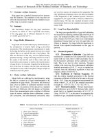
4 Refer to Fig. 11.1.
Chapter 11
Figure 11.1 Using the object snap modes with C:\BEGIN\DEMODRG.
Beginning with AutoCAD 2002.qxd 14/06/2002 19:04 Page 56
Using object snap from the keyboard
Activate the LINE command and:
prompt Specify first point
enter MID <R>
prompt of
respond 1. move cursor to line D1 and leave for few seconds
2. coloured triangular marker at line midpoint
3. Midpoint tooltip displayed in colour
now pick line D1, i.e. left-click
and line ‘snaps to’ the midpoint of D1
prompt Specify next point
enter PERP <R>
prompt to
respond pick line D2 – note coloured Perpendicular marker
prompt Specify next point
enter CEN <R>
prompt of
respond pick circle D3 – note coloured Center marker
prompt Specify next point
enter INT <R>
prompt of
respond pick point D4 – note blue Intersection marker
prompt Specify next point
respond right-click and pick Enter to end the line sequence.
Using object snap from the toolbar
Activate the LINE command and:
prompt Specify first point
respond pick the Snap to Nearest icon
prompt nea to
respond pick any point on line K1
prompt Specify next point
respond pick the Snap to Apparent Intersection icon
prompt appint of
respond pick line K2
prompt and
respond pick line K3
prompt Specify next point
respond pick the Snap to Perpendicular icon
prompt per to
respond pick line K4
prompt Specify next point
respond pick the Snap to Tangent icon
prompt tan to
respond pick circle K5
prompt Specify next point
respond pick the Snap to Midpoint icon
prompt mid of
respond pick line K6
prompt Specify next point
respond pick the Snap to Quadrant icon
prompt qua of
respond pick circle K7
prompt Specify next point
respond pick the Snap to Endpoint icon
prompt endp of
respond pick line K8
prompt Specify next point
respond right-click and pick Enter to end the line sequence.
Object snap 57
Beginning with AutoCAD 2002.qxd 14/06/2002 19:04 Page 57
Object snap with circles
Select the CIRCLE icon from the Draw toolbar and:
prompt Specify center point for circle or
respond pick the Snap to Midpoint icon
prompt mid of
respond pick line P1
prompt Specify radius of circle or
respond pick the Snap to Center icon
prompt cen of
respond pick circle P2.
Note
1 Save your drawing at this stage as C:\BEGIN\DEMODRG.
2 The endpoint ‘snapped to’ depends on which part of the line is ‘picked’. The coloured
marker indicates which line endpoint.
3 A circle has four quadrants, these being at the 3, 12, 9, 6 o’clock positions. The coloured
marker indicates which quadrant will be snapped to.
The extension and parallel object snap modes
The object snap modes selected so far should have been self-explanatory to the user, i.e.
endpoint will snap to the end of a line, center will snap to the centre of a circle, etc. The
extension and parallel modes are used as follows:
a) Extension: used with lines and arcs and gives a temporary extension line as the
cursor is passed over the endpoint of an object
b) Parallel: used with straight line objects only and allows a vector to be drawn
parallel to another object.
58 Beginning AutoCAD 2002
Beginning with AutoCAD 2002.qxd 14/06/2002 19:04 Page 58
To demonstrate these two object snap modes:
1 Continue with the DEMODRG and turn on the grid and snap. Set the spacing to 10 for both.
2 Activate the LINE command and:
prompt Specify first point
respond pick the Snap to Extension icon
prompt ext of
respond move cursor over point W1 then drag to right
and 1. highlighted extension line dragged out
2. information displayed about distance from endpoint as a tooltip
respond 1. move cursor until Extension: 50.00<0.0 displayed
2. left-click
prompt Specify next point
respond pick the Snap to Extension icon
prompt ext of
respond 1. move cursor over point W2
2. move cursor vertically up until Extension:40.00<90.0 is displayed
3. left-click
prompt Specify next point
respond pick the Snap to Parallel icon
prompt par to
respond 1. move cursor over line W3, leave for a few seconds and note the display
2. move cursor to right of last pick point and:
a) highlighted line
b) information about distance and angle displayed
3. move cursor to right until 70.00<0.0 displayed
4. left-click
prompt Specify next point
respond pick the Snap to Parallel icon
prompt par to
respond 1. move cursor over line W4
2. move cursor vertically below last pick point
3. move cursor until 140.00<270.0 displayed
4. left-click
prompt Specify next point
enter C <R> to close the shape and end the line command
3 The line segments should be as Fig. 11.1
4 Save your layout as C:\BEGIN\DEMODRG, updating the existing DEMODRG.
Running object snap
Using the object snap icons from the toolbar will increase the speed of the draughting
process, but it can still be ‘tedious’ to have to pick the icon every time an ENDpoint (for
example) is required. It is possible to ‘preset’ the object snap mode to ENDpoint,
MIDpoint, CENter, etc., and this is called a running object snap. Pre-setting the object
snap does not preclude the user from selecting another mode, i.e. if you have set an
ENDpoint running object snap, you can still pick the INTersection icon.
The running object snap can be set:
1 From the menu bar with Tools-Drafting Settings and pick the Object Snap tab
2 Entering OSNAP <R> at the command line
3 Picking the Object Snap Settings icon from the Object Snap toolbar
4 With a right-click on OSNAP in the Status bar and picking Settings
Each method displays the Drafting Settings dialogue box with the Object Snap tab active.
Object snap 59
Beginning with AutoCAD 2002.qxd 14/06/2002 19:04 Page 59
Task
1 Select Tools-Drafting Settings from the menu bar and:
prompt Drafting Settings dialogue box
respond 1. ensure the Object Snap tab is active
2. ensure Object Snap On (F3) is active
3. activate Endpoint, Midpoint and Nearest by picking the appropriate box –
tick means active
4. dialogue box as Fig. 11.2
5. pick OK.
2 Now activate the LINE command and move the cursor cross-hairs onto any line and
leave it.
3 A coloured marker will be displayed at the Nearest point of the line – it may be that you
have the midpoint marker displayed.
4 Press the TAB key to cycle through the set running object snaps, i.e. the line should
display the cross, square and triangular coloured markers for the Nearest, Endpoint and
Midpoint object snap settings.
5 Cancel the line command with ESC.
60 Beginning AutoCAD 2002
Figure 11.2 The Drafting Settings dialogue box with the Object Snap tab active.
Beginning with AutoCAD 2002.qxd 14/06/2002 19:04 Page 60
AutoSnap and AutoTrack
The Object Snap dialogue box allows the user to select Options which displays the
Drafting tab dialogue box – Fig. 11.3. With this dialogue box, the user can control both
the AutoSnap and the AutoTrack settings which can be simply defined as:
a) AutoSnap: a visual aid for the user to see and use object snaps efficiently, i.e. a
marker and tooltip displayed.
b) AutoTrack: an aid to the user to assist with drawing at specific angles, i.e. polar
tracking.
The settings which can be altered with AutoSnap and AutoTrack are:
AutoSnap AutoTrack
Marker Display polar tracking vector
Magnet Display full screen tracking vector
Display tool tip Display autotrack tooltip
Display aperture box Alter alignment point acquisition
Alter marker colour Alter aperture size
Alter marker size.
The various terms should be self-explanatory at this stage(?):
a) Marker: is the geometric shape displayed at a snap point.
b) Magnet: locks the aperture box onto the snap point.
c) Tool tip: is a flag describing the name of the snap location.
The rest of the options should be apparent. It is normal to have the marker, magnet and
tool tip active (ticked). The colour of the marker and the aperture box sizes are at the
user’s discretion, as is having polar tracking ‘on’.
Object snap 61
Figure 11.3 The Drafting tab of the Options dialogue box.
Beginning with AutoCAD 2002.qxd 14/06/2002 19:04 Page 61
Cancelling a running object snap
A running object snap can be left ‘active’ once it has been set, but this can cause problems
if the user ‘forgets’ about it. The running snap can be cancelled:
1 From the Object Settings dialogue box with Clear All.
2 By entering –OSNAP <R> at the command line and:
prompt Enter list of object snap modes
enter NONE <R>
3 Note:
a) Selecting the Snap to None icon from the Object Snap toolbar will turn off the object
snap running modes for the next point selected.
b) Using the Object Snap dialogue box is the recommended way of activating and
de-activating object snaps.
The Snap From object snap
This is a very useful object snap, allowing the user the reference points relative to existing
objects.
1 Using the squares and circles which should still be displayed, erase the lines and circle created
with the object snaps. This is to give ‘some space’. Ensure the Object Snap toolbar is displayed.
2 Activate the circle command and:
prompt Specify center point for circle
respond pick Snap From icon from the Object Snap toolbar
prompt from Base Point
respond pick Snap to Midpoint icon
prompt mid of
respond pick line K8
prompt <Offset>
enter @50,0 <R>
prompt Specify radius of circle
enter 20 <R>
3 A circle is drawn with its centre 50mm horizontally from the midpoint of the selected line
4 Select the LINE icon and:
prompt Specify first point
respond pick Snap From icon
prompt from Base point
respond pick Intersection icon
prompt int of
respond pick point W1
prompt <Offset>
enter @25,25 <R>
prompt Specify next point
respond pick Snap From icon
prompt from Base point
respond pick Snap to Centre icon
prompt cen of
respond pick circle K7
prompt <Offset>
enter @80<–20 <R>
prompt Specify next point
respond right-click and Enter.
5 A line is drawn between the specified points. The endpoints of this line have been ‘offset’
from the selected objects by the entered coordinate values.
6 Do not save these additions to your drawing layout.
62 Beginning AutoCAD 2002
Beginning with AutoCAD 2002.qxd 14/06/2002 19:04 Page 62
Object Snap Tracking
Object snap tracking allows the user to ‘acquire coordinate data’ from the object snap
modes which have been set. To demonstrate this drawing aid:
1 Erase all squares, circles, etc. from the screen to leave the basic rectangular outline.
2 Refer to Fig. 11.4 and draw a line from 50,50 to 100,150 and a circle, centre at 200,200
with radius 50 – fig. (a).
3 Right-click OSNAP from the Status bar, pick Settings and:
prompt Drafting Settings dialogue box with Object Snap tab active
respond a) Object Snap active
b) Endpoint and Center object snap modes active
c) Object Snap Tracking active
d) pick OK.
4 Activate the LINE command and:
a) move the cursor over the top end of the drawn line and the endpoint marker (square)
will be displayed
b) move the cursor vertically upwards to display object snap tracking information, similar
to fig. (b)
c) enter 80 <R> and the start point of the line will be obtained
d) move the cursor to the centre of the circle and the centre marker (circle) will be
displayed
e) move the cursor horizontally to the right and object snap tracking information
displayed similar to fig. (c)
f) enter 78 <R> and a line segment is drawn – fig. (d)
g) move cursor onto bottom end of first line to acquire the endpoint marker then move
horizontally to the right to display object snap tracking data similar to fig. (e)
h) enter 100 <R> then right-click/enter to end the line command
i) the second line segment is complete – fig. (f).
Object snap 63
Figure 11.4 Using Object Snap Tracking to draw line segments.
Beginning with AutoCAD 2002.qxd 14/06/2002 19:04 Page 63
5 Task 1
a) from the Object Snap Settings, deactivate the Endpoint and Center snap modes and
activate the Midpoint snap mode
b) from the Polar Tracking Settings, set the incremental angle to 30
c) activate the circle command and acquire the midpoint of the second line drawn by
object snap tracking
d) move downwards to the right until object snap tracking data displays an angle of 330
degrees
e) enter 50 <R> then 20 <R> for circle radius
f) circle drawn at selected point.
6 Task 2
a) erase the last circle and the two line segments drawn with object snap tracking to
leave the original line and circle
b) set the polar tracking angle to 90
c) turn off the midpoint object snap mode, and activate the endpoint and center modes
d) with the circle command:
1. acquire the endpoint of lower end of line
2. acquire the centre point of the circle
3. move cursor vertically downwards until it is horizontally in line with the lower end
of line
4. the two acquired point object snap tracking data should be displayed similar to
Fig. 11.5
5. pick this point as the circle centre
6. enter a radius value, e.g. 30
7. think of the benefits of this type of operation, i.e. acquiring centre point data
without any coordinate input.
7 This completes the object snap tracking exercise. Do not save.
64 Beginning AutoCAD 2002
Figure 11.5 Acquiring a circle centre point using object snap tracking.
Beginning with AutoCAD 2002.qxd 14/06/2002 19:04 Page 64
Assignment
1 Open your C:\BEGIN\A3PAPER standard sheet.
2 Refer to Activity 4 and draw the three components using lines and circles.
3 The Object snap modes will require to be used and hints are given.
4 When complete, save as C:\BEGIN\ACT4.
5 Read the summary then progress to the next chapter.
Summary
1 Object snap (OSNAP) is used to reference existing objects.
2 The object snap modes are invaluable aids to draughting and should be used whenever
possible.
3 The user can ‘pre-set’ a running objects snap.
4 Geometric markers will indicate the snap points on objects.
5 The Drafting Settings dialogue box allows the user to ‘control’ the geometric markers.
6 Object snap is an example of a transparent command, as it is activated when another
command is being used.
7 The object snap modes can be set and cancelled using the dialogue box or toolbar.
8 Object snap tracking allows the user to ‘acquire’ data for selected points ‘set’ by the object
snap modes.
9 Drawing aids
At this stage the user now has knowledge about the basic 2D draughting aids, these
being:
a) Grid
b) Snap
c) Ortho
d) Object snap modes
e) Polar tracking
f) Object snap tracking.
Object snap 65
Beginning with AutoCAD 2002.qxd 14/06/2002 19:04 Page 65
Arc, donut and ellipse
creation
These three drawings commands will be discussed in turn using our square and circle
drawing. Each command can be activated from the toolbar, menu bar or by keyboard
entry and both coordinate entry and referencing existing objects (OSNAP) will be
demonstrated.
Getting started
1 Open your C:\BEGIN\DEMODRG to display the squares, circles and object snap lines,
etc.
2 Erase the objects created during the object snap exercise.
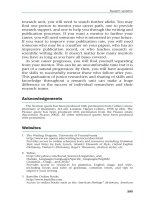
3 Refer to Fig. 12.1 and activated the Draw, Modify and Object Snap toolbars.
Chapter 12
Figure 12.1 Arc, donut and ellipse creation with C:\BEGIN\DEMODRG.
Beginning with AutoCAD 2002.qxd 14/06/2002 19:04 Page 66
Arcs
There are ten different arc creation methods. Arcs are normally drawn in an anti-
clockwise direction with combinations of the arc start point, end point, centre point,
radius, included angle, length of arc, etc. We will investigate four different arc creation
methods as well as continuous arcs. You can try the others for yourself.
Start,Center,End
From the menu bar select Draw-Arc-Start,Center,End and:
prompt Specify start point of arc
respond Snap to Midpoint icon and pick line D1
prompt Specify center point of arc
respond Snap to Center icon and pick circle D2
prompt Specify end point of arc
respond Snap to Midpoint icon and pick line D3.
Start,Center,Angle
Menu bar with Draw-Arc-Start,Center,Angle and:
prompt Specify start point of arc
respond Snap to Intersection icon and pick point K1
prompt Specify center point of arc
respond Snap to Center icon and pick circle K2
prompt Specify included angle
enter –150 <R>
Note that negative angle entries draw arcs in a clockwise direction.
Start,End,Radius
Menu bar again with Draw-Arc-Start,End,Radius and:
prompt Start point and snap to Endpoint of arc P1
prompt End point and snap to Intersection of point P2
prompt Radius and enter 50 <R>
Three points (on arc circumference)
Activate the 3 Points arc command and:
prompt Start point and snap to Center of circle B1
prompt Second point and snap to Intersection of point B2
prompt End point and snap to Midpoint of line B3
Continuous arcs
1 Activate the 3 Points arc command again and:
prompt Start point and enter 25,25 <R>
prompt Second point and snap to Midpoint of line T1
prompt End point and enter @50,–30 <R>
2 Select from the menu bar Draw-Arc-Continue and:
prompt End point, and cursor snaps to end point of the last arc drawn
enter @50,0 <R>
3 Repeat the Arc-Continue selection and:
prompt End point
respond snap to Center of circle K2.
Arc, donut and ellipse creation 67
Beginning with AutoCAD 2002.qxd 14/06/2002 19:04 Page 67
Donut
A donut (doughnut) is a ‘solid filled’ circle or annulus (a washer shape), the
user specifying the inside and outside diameters and then selecting the donut centre
point.
1 Menu bar with Draw-Donut and:
prompt Specify inside diameter of donut and enter: 0 <R>
prompt Specify outside diameter of donut and enter: 15 <R>
prompt Specify center of donut and enter: 40,245 <R>
prompt Specify center of donut
respond Snap to Center of circle X1
prompt Specify center of donut
respond Snap to Center of arc X2
prompt Specify center of donut and right-click.
2 Repeat the donut command and:
prompt Specify inside diameter of donut and enter: 40 <R>
prompt Specify outside diameter of donut and enter: 45 <R>
prompt Specify center of donut and enter: 220,255 <R>
prompt Specify center of donut
respond Snap to Intersection of point Y1
prompt Specify center of donut and right-click.
3 Note: the donut command allows repetitive entries to be made by the user, while the circle
command only allows one circle to be created per command – I don’t know why
this is!
Ellipse
Ellipses are created by the user specifying:
a) either the ellipse centre and two axes endpoints
b) or three points on the axes endpoints.
1 Select from the menu bar Draw-Ellipse-Center and:
prompt Specify center of ellipse and enter: 350,150 <R>
prompt Specify endpoint of axis and enter: 400,150 <R>
prompt Specify distance to other axis and enter: 350,120 <R>
2 Select the ELLIPSE icon from the Draw toolbar and:
prompt Specify axis endpoint of ellipse or (Arc/Center)
enter C <R> – the center option
prompt Specify center of ellipse
respond Snap to Center icon and pick the existing ellipse
prompt Specify endpoint of axis and enter: @30,0 <R>
prompt Specify distance to other axis and enter: @0,60 <R>
3 Menu bar with Draw-Ellipse-Axis,End and:
prompt Specify axis endpoint of ellipse
respond Snap to Intersection of point F1
prompt Specify other endpoint of axis
respond Snap to Midpoint of line F2
prompt Specify distance to other axis or [Rotation]
enter R <R> – the rotation option
prompt Specify rotation around major axis and enter: 60 <R>
68 Beginning AutoCAD 2002
Beginning with AutoCAD 2002.qxd 14/06/2002 19:04 Page 68
Note
1 At this stage your drawing should resemble Fig. 12.1, but without the text.
2 Save the layout as C:\BEGIN\DEMODRG for future recall if required. Remember that this
will ‘over-write’ the existing C:\BEGIN\DEMODRG file.
3 Arcs, donuts and ellipses have centre points and quadrants which can be ‘snapped to’
with the object snap modes.
4 It is also possible to use the tangent snap icon and draw tangent lines, etc. between these
objects. Try this for yourself.
Solid fill
Donuts are generally displayed on the screen ‘solid’, i.e. ‘filled in’. This solid fill effect is
controlled by the FILL system variable and can be activated from the menu bar or the
command line.
1 Still with the DEMODRG layout on the screen?
2 Menu bar with Tools-Options and:
prompt Options dialogue box
respond pick the Display tab
then 1. Apply solid fill OFF, i.e. no tick in box
2. pick OK.
3 Menu bar with View-Regen and the donuts will be displayed without the fill effect.
4 At the command line enter FILL <R>
prompt Enter mode [ON/OFF] <OFF>
enter ON <R>
5 At the command line enter REGEN <R> to ‘refresh’ the screen and display the donuts
with the fill effect.
6 Note: this fill effect also applies to polylines, which will be discussed in a later chapter.
Arc, donut and ellipse creation 69
Beginning with AutoCAD 2002.qxd 14/06/2002 19:04 Page 69
Summary
Arcs, donuts and ellipses are Draw commands and can be created by coordinate entry
or by referencing existing objects.
General
1 The three objects have a centre point and quadrants.
2 They can be ‘snapped to’ with the object snap modes.
3 Tangent lines can be drawn to and from them.
Arcs
1 Several different creation options.
2 Normally drawn in an anti-clockwise direction.
3 Very easy to draw in the wrong ‘sense’ due to the start and end points being selected
wrongly.
4 Continuous arcs are possible.
5 A negative angle entry will draw the arc clockwise.
Donuts
1 Require the user to specify the inside and outside diameters.
2 Can be displayed filled of unfilled.
3 An inside radius of 0 will give a ‘filled circle’.
4 Repetitive donuts can be created.
Ellipses
1 Two creation methods.
2 Partial ellipses (arcs) are possible.
3 The created ellipses are ‘true’, i.e. have a centre point.
70 Beginning AutoCAD 2002
Beginning with AutoCAD 2002.qxd 14/06/2002 19:04 Page 70
Layers and standard
sheet 2
All the objects that have been drawn so far have had a continuous linetype and no
attempt has been made to introduce centre or hidden lines, or even colour. AutoCAD
has a facility called LAYERS which allows the user to assign different linetypes and
colours to named layers. For example, a layer may for red continuous lines, another may
be for green hidden lines, and yet another for blue centre lines. Layers can also be used
for specific drawing purposes, e.g. there may be a layer for dimensions, one for hatching,
one for text, etc. Individual layers can be ‘switched’ on/off by the user to mask out
drawing objects which are not required.
The concept of layers can be imagined as a series of transparent overlays, each having its
own linetype, colour and use. The overlay used for dimensioning could be switched off
without affecting the remaining layers. Figure 13.1 demonstrates the layer concept with:
a) Five layers used to create a simple component. Each ‘part’ of the component has been
created on ‘its own’ layer.
b) The layers ‘laid on top of each other’. The effect is that the user ‘sees’ one component.
Chapter 13
Figure 13.1 Layer concept.
Beginning with AutoCAD 2002.qxd 14/06/2002 19:04 Page 71
The following points are worth noting when considering layers:
1 All objects are drawn on layers.
2 Layers should be used for each ‘part’ of a drawing, i.e. dimensions should not be on the
same layer as centre lines (for example).
3 New layers must be ‘created’ by the user, using the Layer Properties Manager dialogue
box.
4 Layers are one of the most important concept in AutoCAD.
5 Layers are essential for good and efficient draughting.
As layers are very important, and as the user must have a sound knowledge of how they
are used, this chapter is therefore rather long (and perhaps boring). I make no apology
for this, as all CAD operators must be able to use layers correctly.
As a point of interest, try and complete this chapter at ‘the one sitting’ as it is important
for all future drawing work.
Getting started
Several different aspects of layers will be demonstrated in this chapter. Once these
concepts have been discussed, we will modify our existing standard sheet, so:
1 Open your C:\BEGIN\A3PAPER standard sheet.
2 Draw a horizontal and vertical line each of length 200, and a circle of radius 75 anywhere
on the screen.
The Layer Properties Manager dialogue box
1 From the menu bar select Format-Layer … and:
prompt Layer Properties Manager dialogue box
respond Study the layout of the dialogue box.
2 The Layer Properties Manager dialogue box has a number of distinct ‘sections’ as
follows:
a) Named layer filter with options:
1. Show all layers – usually active
2. Show all used layers – very useful to the user
3. Show all Xref dependent layers
4. Invert filter and Apply to Object Property toolbar toggle.
b) Six selections: New, Delete, Current, Show details, Save state, Restore state.
c) Current Layer: 0 – at present.
d) Layer information display with:
Name: only 0 at present
Three layer states: On, Freeze, (L)ocked
Color: White (with a black box)
Linetype: Continuous
Lineweight: Default
Plot Style Color_7 (probably?)
Plot Printer icon.
3 Layer 0 is the layer on which all objects have so far been drawn, and is ‘supplied’ with
AutoCAD. It is the current layer and is displayed in the Objects Properties toolbar with
the layer state icons.
72 Beginning AutoCAD 2002
Beginning with AutoCAD 2002.qxd 14/06/2002 19:04 Page 72
4 Certain areas of the dialogue box are ‘greyed out’, i.e. inactive.
5 Move the pointing device arrow onto the 0 named line and:
a) pick with a left-click
b) the ‘complete line’ is highlighted in colour
c) pick Show Details to reveal other information about the selected layer as Fig. 13.2.
6 Move the cursor along the highlighted area and pick the On/Off icon which is a yellow
light bulb (indicating ON) and:
prompt AutoCAD layer message box – Fig. 13.3
and On/Off icon now a blue light bulb, indicating OFF
respond 1. pick OK from the message box
2. pick OK from the Layer Properties Manager dialogue box
and the drawing screen will be returned and no objects are displayed – they were
all drawn on layer 0 which has been turned off.
7 Re-activate the Layer Properties Manager dialogue box and:
a) pick the 0 layer name – highlighted in colour
b) pick the ‘blue light’ and it changes to yellow (ON)
c) pick OK.
8 The line and circle objects displayed – layer 0 is on.
Layers and standard sheet 2 73
Figure 13.2 The Layer Properties Manager dialogue box.
Figure 13.3 Layer Message dialogue box.
Beginning with AutoCAD 2002.qxd 14/06/2002 19:04 Page 73
Linetypes
AutoCAD allows the user to display objects with different linetypes, e.g. continuous, centre,
hidden, dotted, etc. Until now, all objects have been displayed with continuous linetype.
1 Activate the menu selection Format-Layer and:
prompt Layer Properties Manager dialogue box
respond pick Continuous from layer 0 ‘line’
prompt Select Linetype dialogue box
with Loaded linetypes:
Linetype Appearance Description
Continuous __________ Solid line
respond pick Load …
prompt Load or Reload Linetype dialogue box
with a) Filename: acadiso.lin
b) a list of all linetypes in the acadiso.lin file
respond 1. scroll (at right) and pick CENTER – Fig. 13.4
2. hold down the Ctrl key
3. scroll and pick HIDDEN
4. pick OK from Load or Reload Linetypes dialogue box
prompt Select Linetype dialogue box
with Loaded Linetypes:
Linetype Appearance Description
CENTER ___ _ ___ _ ___ Center___ _ ___ _ ___
Continuous _______________ Solid line
HIDDEN _____ _____ ___ Hidden__ __ __ __ __
result Figure 13.5, i.e. we have loaded the CENTER and HIDDEN linetypes from the
acadiso.lin file into our drawing and they are now ready to be used
respond 1. pick CENTER – it becomes highlighted
2. pick OK from Select Linetype dialogue box
prompt Layer Properties Manager dialogue box
with layer 0 having CENTER linetype
respond pick OK from Layer Properties Manager dialogue box.
74 Beginning AutoCAD 2002
Figure 13.4 Load or Reload Linetypes dialogue box.
Beginning with AutoCAD 2002.qxd 14/06/2002 19:04 Page 74
2 The drawing screen will display the three objects and the border with center linetype
appearance. Remember that AutoCAD is an American package – hence center, and not
centre.
3 Note
Although we have used the Layer Properties Manager dialogue box to ‘load’ the CENTER
and HIDDEN linetypes, linetypes can also to loaded by selecting from the menu bar
Format-Linetype and the Linetype Manager dialogue box will be displayed. The
required linetypes are loaded ‘into the current drawing’ in the same manner as
described.
Colour
Individual objects can be displayed on the screen in different colours, but I prefer to use
layers for the colour effect. This is achieved by assigning a specific colour to a named
layer and will be discussed later in the chapter.
For this exercise:
1 Activate the Layer Properties Manager dialogue box with Show Details active.
2 a) Pick line 0 to activate the layer information
b) pick the scroll arrow at Details Color: White to display the seven standard colours
c) pick Red and:
i) White alters to Red at Details Color
ii) layer 0 line displays Color: red square Red
d) pick OK.
3 The screen displays the objects with red centre lines.
4 Note the Object Properties toolbar which displays:
a) layer 0 with a red square
b) the ByLayer colour is a red square
c) the ByLayer linetype has a center linetype appearance.
Layers and standard sheet 2 75
Figure 13.5 Select Linetype dialogue box.
Beginning with AutoCAD 2002.qxd 14/06/2002 19:04 Page 75
Task
By selecting the Layers icon from the Object Properties toolbar, use the Layer Properties
Manager dialogue box to:
a) set layer 0 linetype to Continuous
b) set layer 0 colour to White/Black
c) screen should display the original continuous white/black objects
d) note the Object Properties toolbar.
Note on colour
1 The default AutoCAD colour for objects is dependent on your screen configuration, but
is generally:
either a) white background with black lines
or b) black background with white lines.
2 The white/black linetype can be confusing?
3 All colours in AutoCAD are numbered. There is a total of 255 colours, but the seven
standard colours are:
1 red 2 yellow 3 green 4 cyan 5 blue 6 magenta 7 black/white.
4 The number or colour name can be used to select a colour. The numbers are associated
with colour pen plotters.
5 The complete 255 ‘colour palette’ can be activated from:
a) Layer Program Manager dialogue box by picking the coloured square under Color
b) from the Details: Color by scrolling and picking Others …
6 Generally only the seven standard colours will be used in the book, but there may be
the odd occasion when a colour from the palette will be selected.
Creating new layers
Layers should be made to suit individual or company requirements, but for our purposes
the layers which will be made for all future drawing work are:
Usage Layer name Layer colour Layer linetype
General 0 white/black continuous
Outlines OUT red continuous
Centre lines CL green center
Hidden detail HID number 12 hidden
Dimensions DIMS magenta continuous
Text TEXT blue continuous
Hatching SECT number 74 continuous
Construction CONS to suit continuous
These seven layers must be ‘made’ by us (remember that layer 0 is given to us) so:
1 Close the existing drawing (no to save changes) then open your A3PAPER standard sheet
2 Menu bar with Format-Layer and:
prompt Layer Properties Manager dialogue box
respond pick New
and Layer1 added to layer list with the same properties as layer 0, i.e. white colour
and continuous linetype
respond pick New until 7 new layers are added to the layer list, i.e. 8 layers in total:
a) the original layer 0 and
b) the added new layers, named layer1-layer7
a) naming the new layers
1. move pick arrow onto layer1 and pick it – highlighted
2. Show details active
3. at Details, highlight Layer1 name and enter OUT
4. Layer1 is renamed OUT in the layer list
5. repeat the above steps and rename layer2-layer7 with the following names:
layer2: CL layer3: HID layer4: DIMS
layer5: TEXT layer6: SECT layer7: CONS
76 Beginning AutoCAD 2002
Beginning with AutoCAD 2002.qxd 14/06/2002 19:04 Page 76
b) assigning the linetypes
1. pick layer line CL
2. move pick arrow to Linetype-Continuous and pick it
3. from the Select Linetype dialogue box, pick Load and load the CENTER and
HIDDEN linetypes from the acadiso.lin file as discussed earlier
4. when the CENTER and HIDDEN linetype are displayed in the Select Linetype
dialogue box, pick CENTER then OK
5. pick layer line HID
6. move pick arrow to Linetype-Continuous and pick it
7. the Select Linetype dialogue box should display HIDDEN
8. pick HIDDEN then OK
9. Layer Properties Manager dialogue box and layer CL should have a CENTER
linetype, and layer HID a HIDDEN linetype
c) assigning the colours
1. pick layer line OUT
2. scroll at Details-Color and pick Red
3. pick the other layer lines and set the following colours:
CL: green HID: number 12 DIMS: magenta
TEXT: blue SECT: number 74 CONS: colour to suit.
3 At this stage the Layer Properties Manager dialogue box should resemble Fig. 13.6.
4 Pick OK from the Layer Properties Manager dialogue to save the layers (with linetypes
and colours) which have been created.
Layers and standard sheet 2 77
Figure 13.6 The Layer Properties Manager dialogue box with colours and linetypes set.
Beginning with AutoCAD 2002.qxd 14/06/2002 19:04 Page 77