Failure Analysis Case Studies II Episode 10 pot
Bạn đang xem bản rút gọn của tài liệu. Xem và tải ngay bản đầy đủ của tài liệu tại đây (927.51 KB, 35 trang )
303
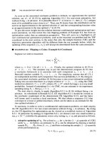
Fig.
2.
Crevice corrosion suffered by the
316L
stainless steel pump. Small crystals
of
sodium chloride can be
seen
on
and around the corroded area.
corresponding volumes would be 204.1 and 0.23 1, respectively. There is a slight
(-
0.3%) increase
in volume on mixing.
Data for the solubility of sodium chloride in water-butanone mixtures could not be found.
However, there are data for the solubility of sodium chloride in water-acetone mixtures at 20 "C
[3].
These are given in Table
2.
The 'lower' and 'upper' layers in Table
2
refer to the water- and acetone-rich solutions, respec-
tively. Comparison of the data in Table
2
and the water-butanone phase diagram shown in Fig.
1
shows that the solubility
of
acetone in water is roughly comparable to that of butanone in water,
and that water is more soluble in acetone than in butanone. Thus, the solubility of sodium chloride
in water-acetone mixtures should only be considered as a guide to what might happen in water-
butanone mixtures. Although the lower and upper layers in the immiscible water-acetone mixtures
are in equilibrium, and the activity of the sodium chloride in each layer is therefore equal, inspection
of Table
2
shows that in acetone-water mixtures the partition coefficient for sodium chloride
between the water-rich lower layer and acetone-rich upper layer is 40:
1.
If in the present case of a two-liquid water-butanone mixture, the partition of sodium chloride
between the water-rich phase and the butanone-rich phase is of a similar magnitude, calculations
indicate that the concentration of sodium chloride in the water-rich phase will be higher than in
both the butanone-rich phase and the original
8
wt% solution of distilled water in butanone.
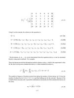
Table
2.
Solubility of sodium chloride in aqueous solutions
of
acetone at
20
"C
Weight
%
acetone
8.0 16.5 25.3 27.1 84.1 85.3 87.7
Lower layer Upper layer
E
NaCl Der
100
cm3 of solution
27.18 23.10 19.32 18.05 0.45 0.43 0.25
304
'l'he weight of sodium chloride in the 168 kg of the liquor used in the batch process is 0.084 kg.
With a partition coefficient of
40:1,
this amount of sodium chloride would be partitioned thus: the
water-rich layer would contain
0.082
kg, and the butanone-rich layer would contain 0.002 kg. The
calculations given previously show that addition of the minimum volume of water required to cause
separation of the
8%
water-in-butanone solution used in the batch process into two immiscible
liquids results in the formation of 0.23
1
of the water-rich phase. Using the data shown in Table 2
as a guide, the greatest amount of sodium chloride which could dissolve in 0.231 of water-rich
solution is 0.045 kg. Thus, if only
0.23
1
of the water-rich phase had been formed, it is probable that
sodium chloride would have precipitated from the water-rich phase.
Since no solids had been observed when the system was dismantled, it appears that at least 0.5 kg
of water-rich phase must have been formed. This led to a reappraisal of the amount of water which
had been introduced to the system. Calculations based on the Lever rule indicated that this would
have required the addition of just under
4
kg of water to the feed liquor.
Although the strict applicability of these calculations to the present case may be questioned, since
data for the solubility of sodium chloride in water-acetone mixtures have been used, they do suggest
that the hypothesis is tenable. The result would have been that the pump which had suffered the
crevice corrosion was not exposed to a very dilute solution of chloride but to a brine, and crevice
corrosion of 3 16L would inevitably have occurred.
5.
A
DEMONSTRATION
Since there were doubts about the applicability of these calculations to the present case, a
demonstration was carried out in which
5
mm nominal diameter 3
16L
stainless steel rods were
exposed to: (i) an
8
wt%a solution of water in butanone which contained
0.05
wt% sodium chloride,
and (ii) the same solution after the addition of just sufficient water to cause the formation of two
liquids. Artificial crevices were formed by slipping Viton O-rings up the rod. In the second case, the
O-rings were positioned
so
that there was one in the water-rich phase and one in the butanone-rich
phase. The composition of the stainless steel used in this demonstration is given in Table 3.
After
12
days of exposure at
25
"C,
a pale yellow discolouration of the originally clear water-rich
phase was observed, and a light ring of rust began to appear at the edge of the O-ring immersed in
this phase (Fig. 3). Neither discolouration of the solutions nor rings of rust at the O-rings were
Fig.
3.
Light ring of rust which appeared at the O-ring immersed
in
the water-rich phase after
12
days of
exposure at
25
"C
(
x
16)
305
Table
3.
Chemical analysis
of
the stainless steel rod used in the demonstration: composition in wt%
C
Mn Si
P
S
Cr Ni Mo
Rods
0.024
1.55
0.59
0.030 0.023
16.3
11.1
2.02
UNS
S31603 0.03
2.00
1
.oo
0.045
0.030
16.0-18.0 10.0-14.0
2.00-3.00
maximum maximum maximum maximum maximum
observed in either the butanone-rich phase or the original 8
wt%
water-in-butanone mixture. These
observations show that crevice corrosion had just begun to initiate in the water-rich phase, but had
not initiated in either the 8wt% solution of water in butanone, or in the butanone-rich phase formed
after the addition of water.
6.
CONCLUSION
The hypothesis presented in the discussion is tenable, and can explain how crevice corrosion of
316L occurred in what was supposed to
be
a very dilute solution
of
sodium chloride in an 8 wt%
solution
of
water in butanone.
The unresolved question was how the additional water required to cause separation of this
solution into two immiscible liquids was introduced into the system.
REFERENCES
I.
Francis,
A.
W.,
LiquicCLiquid Equilibriums.
Interscience, New York,
1963.
2.
Seidell,
A,,
Solubilities
oforganic
Compounds,
3rd
edn.
Van Nostrand, Princeton, NJ,
1941.
3.
Seidell,
A.,
Solubilities
oflnorganic
Compounds,
3rd edn. Van Nostrand, Princeton, NJ,
1941.
Failure Analysis Case Studies
II
D.R.H. Jones (Editor)
0
2001
Elsevier Science Ltd.
All
rights reserved
307
TYPE I PITTING
OF
COPPER TUBES FROM A WATER
DISTRIBUTION SYSTEM
PAUL0
J.
L.
FERNANDES
Advanced Engineering and Testing
Services,
MATTEK,
CSIR,
Private Bag
X28.
Auckland Park,
2006,
South Africa
(Received
9
Augusf
1997)
Abstract-Samples of copper tubes from a cold water distribution system which had failed due to pitting
whilst in service were subjected to a detailed failure investigation. Analysis of the tubes showed that failure
was a result of
Type
I
pitting attack. While the exact cause of pitting was unknown, it was hypothesised that
it could have been due to changes in the water quality and/or content. The tubes were found to be made from
phosphorus de-oxidised copper and
no
anomalies were evident
in
either the chemical composition or the
microstructure which could have caused the pitting observed. It was recommended that the tubes be replaced
and that due attention be given to ensure that the new tubes are free
of
internal carbonaceous deposits
or
other foreign matter.
0
1998
Elsevier Science Ltd.
All
rights reserved.
Keywords Corrosion, pitting corrosion.
1.
INTRODUCTION
Copper tubes are used extensively in water distribution systems due to their corrosion resistance
and ease of installation.
In
Europe and North America they account for more than
80%
of
all tubes
installed in water
service
[l],
amounting to over
100
million metres of tubing. In spite
of
these large
quantities, tube failures are relatively rare. Of the failures that do occur, pitting corrosion accounts
for
approximately
60%.
This study presents an investigation of the failure of copper tubes from a cold water distribution
system carrying potable water in a shopping centre. The tubes, which were built into the brick walls,
sprang leaks in several premises in the shopping centre after approximately
12
years’
seMce,
causing
severe staining of the walls. Examination of the tubes revealed the presence of pin holes perforating
the tube walls.
2
EXPERIMENTAL PROCEDURE
2.1.
Visual examination
Several tubes sections were received
for
analysis. These were sectioned to reveal the internal
surfaces, which were found
to
be covered with
a
greenish-white scale (Fig.
1).
Furthermore, localized
deposits of green corrosion product in the
form
of tubercules were also evident
(see
arrow in Fig.
I).
Some tubercules were carefully removed by light scrubbing
to
reveal the underlying metal. A
shiny, black layer of an unidentified compound was found to exist beneath the greenish-white scale.
Beneath this black layer, in turn, pits penetrating into the tube wall were found. An example
of
the
various layers and the underlying corrosion pit is shown in Fig.
2.
Some
of
the pits observed were
relatively large and deep, as shown in Fig.
3.
2.2.
Chemical analysis
of
internal scale and corrosion products
Samples of the tubes were examined in a scanning electron microscope
(SEM)
equipped with an
energy dispersive spectroscopy of X-rays (EDS) facility. The results of the
EDS
analysis
of
the
greenish-white scale found on the internal surfaces of the tubes are shown in Fig.
4.
The large copper
Reprinted
from
Engineering Failure AnaZysis
5
(l),
35-40
(1
998)
80E
309
Fig.
3.
The internal surface of
a
tube showing extensive pitting
(x
3)
Fig.
4.
The
EDS
results of the greenish-white deposits found
on
the internal surfaces
of
the tubes.
3.
METALLOGRAPHY
Samples from the tubes examined were prepared for metallographic analysis using standard
grinding and polishing techniques. Etching was carried out in acidified ferric chloride. The typical
microstructure observed in all cases consisted
of
large equi-axed grains, indicating that the tubes
were in the annealed condition.
310
3.1.
Chemical
anaZysis
An analysis of the chemical composition of the tubes was carried out using a wet chemical analysis
method.
From
the high phosphorus content it was evident that the tubes were made from phosphorus
de-oxidised copper.
4.
TYPE
1
PITTING
Pitting corrosion is the most common failure mechanism for copper tubes in water distribution
systems. Essentially two different types of pitting attack have been identified, and these are referred
to in the literature as Type
I
and Type
I1
pitting*. The former is known as cold water pitting and
occurs more frequently than the latter.
Type
I
pitting is usually encountered in cold water systems carrying borehole
or
well waters free
from organic matter
[I].
It
occurs sporadically and can result in tube wall penetration within a few
months. In some cases, however, penetration occurs only after
15
years
or
more. The internal
surfaces of tubes undergoing Type
I
pitting are usually covered with
a
greenish
scale
of a copper
compound called malachite. Beneath this scale, the tube surface is covered with
a
smooth, shiny
layer of dark cuprite which is very friable and easily spalled
off.
Pits are usually associated with the
presence of tubercules which form over pin hole defects in the cuprite layer.
The characteristics
of
Type
1
pitting attack are such that many pits at all stages of development
can usually be found
[I].
Larger pits are generally linearly arranged along the bottom half
of
horizontal water lines. When pits are very close together, tubercules can extend over a number of
pits
to
form one long tubercule. Although pitting has been observed in annealed, half-hard and
hard-drawn tube, susceptibility is generally greatest in the annealed condition. The pits formed are
usually saucer-shaped and relatively wide.
A
number
of
causes
of
Type
I
pitting have been identified
[I].
Firstly, the incidence
of
pitting has
been associated with the presence
of
carbonaceous films on the internal surface of the tube. These
films are residues of the lubricant used for the drawing operation and which are carbonized during
annealing. The quantity and distribution
of
these films on the internal surface appears
to
affect the
severity
of
pitting. The problems arising from the presence of these carbonaceous films can be
overcome in practice by scouring the tubes with a water-sand or a water-air blast.
Secondly, pitting has been associated with the presence of foreign matter deposits on the bottom
half of horizontal tubes [l]. This is in agreement with observations
on
the preferential location
of
pits discussed above. The foreign matter deposits can be introduced into the water lines in a
number of ways. Metal chips and filings and dirt can be allowed to contaminate the system during
installation. If these are not properly removed before service, they may deposit along sections of
the water lines where the water velocity is low. Foreign matter deposits may also be introduced into
the system in the water
or
may be due to corrosion products formed during surface corrosion
of
the
tubes during service. The concentration of these deposits, and hence their deleterious effects, can be
reduced by the installation
of
filters in the water line.
Thirdly, another factor said to cause pitting attack is the presence
of
soldering pastes on the
insides
of
the tubes. This generally results from bad workmanship and can be avoided by ensuring
that adequate quality standards are maintained during installation. The soldering pastes may act as
deposits in the same way as foreign matter. Alternatively, during soldering
or
brazing these pastes
may be converted to oxides which
form
as
a
thin film on the copper surface. These oxides are
gcncrally cathodic to copper and can therefore give rise to pitting corrosion.
The effect
of
water quality on the incidence of Type
I
pitting is the subject of some controversy
and no consensus has been reached in this regard. Some general observations have been made,
however, on the effects of various constituents and characteristics
of
water on the extent of pitting,
*Some researchers have also reported the existence
of
Type
111
and Type
IV
pitting,
but
these appear to
be
variations
of
Type
I
pitting
[I].
311
+Yes
-No
Is
the
ratio
of
aggressive
C02
to
total
C02
above
0.05?
1
+
Yes
+
yes
+No
Is
the
pH
in the
range
6.8
-
7.51
4
NO
Is
the
ratio
of
sodium
to
nitrate greater than
I?
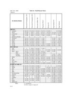
Table
1.
The effect
of
various water constituents and characteristics on Type
I
pitting
Chemical species Effect
Sulphate
(SO:-)
Chloride
(Cl-)
Nitrate
(NO;)
Inhibits pitting
PH
Dissolved oxygen
(0,)
Carbon dioxide
(CO,)
Assists pit initiation and growth, but its effect depends on the concentration
of
other chemical
species.
Essential for pitting attack. Assists the breakdown
of
protective surface films and results in the
formation
of
wide, shallow pits
Increases in pH generally decreasing the probability
of
pitting.
Increased
0,
content increases the probability
of
pitting.
Increased CO, content increases the probability
of
pitting due to a decrease in pH.
and these are summarised in Table
1.
An empirical screening process has also been developed to
assess the risk of Type
I
pitting in various waters
[2]
(Fig.
5).
This process has been used extensively
with reasonable success.
A
number of characteristics of Type
I
pitting discussed above were evident in the failed copper
tubes from the shopping centre. The presence of tubercules of corrosion product and the greenish
scale on the internal surface of the tubes were clearly evident (Fig.
1).
The friable underlying layer
of shiny, dark cuprite was also observed (Fig.
2).
The wide, saucer-shaped pits and their approxi-
mately linear distribution were also evident and are shown in Fig.
3.
It is also evident that pits at
various stages of development were observed.
5.
CONCLUSIONS
It was concluded that the failure of the copper tubes was due
to
Type
I
pitting attack. It is not
clear at
this
stage what the exact cause of pitting failure was, particularly given the fact that pitting
only became evident after
12
years’ service. It is highly unlikely that
it
may
be
due
to
the presence
of foreign matter deposits introduced during installation
of
the system. The introduction of foreign
matter
in
the water is, however,
a
possibility, particularly if the water is not filtered. A change in
water quality or content (e.g. resulting from mixing of the water with borehole
or
well waters) could
also be responsible for pitting.
Once initiated, pitting attack can in some cases be halted through the application
of
appropriate
treatments of the water and the metal. The extent of pitting observed in the present case, however,
0
z
312
suggested that such treatment would be both unsuccessful and unfeasible.
It
was therefore rec-
ommended that the copper tubes be replaced. Careful attention should be given to the usual causes
of
Type I pitting. In particular, it should
be
ensured that all tubes
be
thoroughly cleaned and freed
of
any carbonaceous deposits prior
to
installation. The tubes should also be cleaned to ensure
complete removal
of
any foreign matter deposits and solder pastes after installation. The use of
water filters could also be considered to prevent the introduction
of
foreign matter in the water.
Furthermore, the quality and content
of
the water should
be
determined and its potential
to
cause
pitting assessed. The extent
of
replacement
or
modifications to the water distribution system would,
to some degree, depend
on
the results
of
such water analyses.
REFERENCES
1.
Internnl Corrosion
of
Water Distribution Sysrem.
Report
of
Cooperation Research,
AWWA
Research Foundation,
USA,
2.
Billiau,
M.,
Drapier, C.,
Muteriaux et Techniques,
Nos
1
and
2.
1985.
Failure Analysis Case Studies
II
D.R.H.
Jones (Editor)
0
200
1
Elsevier Science Ltd. All rights reserved
313
CORROSION OF FLEXIBLE WAVEGUIDES
D. PAPATHEODOROU, M. SMITH and
0.
S.
ES-SAID*
Mechanical Engineering Department, Loyola Marymount University, 7900 Loyola Blvd,
Los
Angeles,
CA 90045-8145, U.S.A.
(Received
9
August
1997)
Abstract-Waveguides are commonly used in spacecraft subsystems to convey signals. After noticing a
transponder ouput power drop, borescope inspection of a flexible waveguide revealed a green contaminating
residue on silver plated brass and copper sections. Analysis revealed that the residue, primarily copper hydroxy
nitrate, Cu(OH),N03, was created by exposure of the plating to nitric acid. Possible sources of nitric acid
include inadequate cleanliness after parts were exposed to a nitric acid containing silver bright dip,
or
high
temperature electrical arcing in the presence of air and moisture. Whatever its source, it is suggested that the
waveguide be plated with a more corrosion resistant metal such as rhodium.
0
1998 Elsevier Science Ltd. All
rights reserved.
Keywords:
Corrosion, electronic-device failures, surface coatings.
1.
INVESTIGATION
Flexible waveguides, common in spacecraft payload sub-systems, transport signals between various
units (e.g., filters, transponders, and converters). During preliminary testing at ambient temperature
and pressure, an output power drop was detected within a signal generating unit
of
a waveguide
system. Green contamination residue was found in the waveguides. An investigation commenced
to characterize the corrosion and determine its cause.
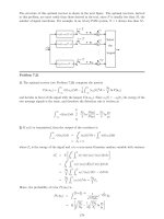
The flexible waveguide, Fig.
1,
has a rectangular thin wall cross section having corrugations which
allow it to be formed. The green residue was found on brass and copper surfaces, primarily in the
bottom
of
those corrugations (dark bands in Fig.
2).
In some areas, the waveguide wall had corroded
through.
To
determine the material damage severity, as well as the composition of the residue, an analysis
of samples taken from the waveguide was conducted using visual inspection, optical microscopy,
scanning electron microscopy and X-ray methods. Samples were prepared by cutting and spreading
open the waveguide to expose its internal surfaces containing many voids and much debris (Fig.
3).
Fig.
1.
Profile of waveguide. Dark bands are low points
in
waveguide
or
corrugations
*Author to whom correspondence should be addressed.
Reprinted from
Engineering Failure Analysis
5
(l),
49-52
(1998)
Fig
2
Inner surface
of
waveguide
L_cx
,
Fig.
3
Debris
on waveguide surface Copper hydroxy nitrate corrosion along corrugations in waveguide
Fig.
4
Corrosion product along corrugations in the waveguide
315
In addition
to
pitting of the silver plating, there were burnt areas where it appeared as if silver
plating had been melted by electrical arcing.
Closer investigation of the pitted areas seemed to show that corrosion
on
the waveguide internal
passages probably started on the exposed silver plated surface. It is theorized that these pits, however
formed, allowed attack of the underlying copper bearing base material.
A chemical analysis using X-ray diffraction analysis, subsequently verified by Fourier transform
infrared spectroscopy and energy dispersive X-ray spectroscopy, revealed that the debris is primarily
copper hydroxy nitrate Cu(OH),N03. To determine how it got there, a laboratory test was per-
formed to try to create the same debris on clean waveguide samples by placing on them a small
amount
of
nitric acid. Two hours later, a blue color was observed in the acid. After about
12
h, blue
crystals began forming at the silver plated interface. After
5
days, most
of
the solution had been
replaced by green corrosion analyzed as a copper hydroxy nitrate. Nitric acid clearly caused
the corrosion. Its source could be either faulty fabrication processes or arcing induced chemical
reactions.
2.
FABRICATION PROCESS
The silver plating on the brass waveguide is applied after the brass has undergone
a
multi step
surface preparation process. First, the brass surface is cleaned and etched in a caustic cleaning
solution for
5-60
s.
After subsequent rinsing under running tap water, the brass is immersed in a
bright dip solution for
5-20
s.
This removes scratches and oxide, making the brass look shiny. The
bright dip solution is composed of 5-10% tap water,
60-75%
sulfuric acid,
20-35%
nitric acid. To
remove the bright dip, parts are washed in running tap water. The use of pumice and a brush is
required for assemblies. The bright dip vendor specifies that this cleaning technique is suffcient.
Once bright dipping is complete, parts should
be
first immersed
in
clean running water, then
boiling hot water, and then dried.
To
avoid contamination between one dip operation and another,
parts should
be
rinsed in running water, hot water and then dried at each step [l].
Both silver and copper bright dips exist
to
make either copper or silver shiny. Once silver plating
was complete, a bright dip step may have been inadvertently included despite its lack in vendor
process specifications. For instance,
a
silver bright dip may have been performed to relieve the
effects of poor silver plating, inadvertently leaving behind an acidic residue.
3.
ARCING INDUCED CHEMICAL REACTIONS
If nitric acid was indeed produced by arcing, nitric oxide (NO) would need to be present. Colorless
and noncombustible, nitric oxide can be produced from atmospheric oxygen and nitrogen in the
presence of an electric arc. In this instance, such production is possible-there was evidence
of
arcing on the waveguide surface. In addition, arcing could have initiated pits in the silver plating,
exposing the underlying copper bearing base material to chemical attack.
A similar incident of corrosion in an aircraft waveguide system occurred about
20
years ago. In
that case, arcs were created in a clean noncorroded waveguide while gas samples were taken for an
analysis by mass spectrometry. An analysis of two samples is shown in Table
1.
Table
1.
Mole percent
Sample
#I
Hydrogen
0.001
Water 0.003
Nitrogen 79.816
NO,
as nitric oxide
Oxygen
18.731
Argon
1.015
Carbon dioxide
0.430
39 PPm
Sample
#2
0.003
0.002
79.819
28
pm
18.708
1.022
0.443
316
This confirms that nitric oxide could be formed by electrical arcing. Despite the small concen-
tration, it still exceeds that normally found in air by several orders
of
magnitude. Nevertheless, even
if such nitric oxide is present, it must react with moisture for nitric acid to form. With humidity
controlled between
30
and
6O%,
available evidence suggests that the current waveguide system was
not exposed to excessively moist conditions.
4.
RECOMMENDATIONS
Silver is attacked by nitric acid and will be corroded by reducing acids in the presence of oxidizing
agents
[2].
Nitric acid is a strong oxidizing agent. It oxidizes
all
metals except gold, platinum,
rhodium and iridium [3]. In strong acid solutions, the hydrogen is continuously evolving as bubbles
from the corroding metal and this process continues until either
all
the metal
or
acid is consumed.
If the waveguide system is operated in conditions in which moist air is not absorbed during
operation and if the system is purged
of
any nitric oxide after operation, the corrosion can be
eliminated. It would also be best to pass the air through a dryer prior to introducing it into the
waveguide to guarantee moisture levels are minimized.
For improved protection against nitric acid formation, if arcing does occur, it is best to electroplate
with noble metals other than silver, since it is attacked by nitric acid. The noble metals have
extremely high corrosion stability and do not rely on the formation of an oxide coating. Their high
cost and low strength limits their use to thin films and liners on other structural materials
[4].
They
are economical
for
numerous corrosion applications. Platinum is resistant
to
nitric acid at all
temperatures and concentrations
[5].
Electrodeposited platinum is reasonably dense and generally adheres well. Mechanical and physi-
cal properties depend greatly on plating conditions and thin coatings are used for corrosion and
wear resistant electrical contacts [5].
Gold
is very good in dilute nitric acid and strong sulfuric acid.
Rhodium electroplates well and is used for critical valve parts and other applications where total
resistance to an aggressive environment is necessary
[2].
A
37%
rhodium
63%
nickel alloy has
better resistance to general corrosion than 14 carat yellow gold
[5].
Rhodium finds most of its
applications as an element in platinum to which it imparts added corrosion resistance to many
acids. In general, electrodeposition has been employed for thin rhodium coatings.
A
rhodium
thickness of
5
x
1OP6-2O
x
loP6
inch over silver minimizes tarnishing
[5].
In this case, these metals
can be used for protection against nitric acid if formed due to arcing.
Quality control during waveguide manufacturing must guarantee that no nitrate ions are on the
waveguide. In bright dipping,
a
small amount of metal is corroded but the part has a shiny finish
as opposed to a dull oxide coating. Speed of operation and uniformity are the essentials
of
bright
dipping. The acid acts very quickly and long exposure time will result in more corrosion. After
dipping the parts should be very quickly rinsed in cold water and then hot water and dried
[I].
Pure, clean water, e.g. distilled water, is undoubtedly the best for making solutions. It is very
difficult for small amounts of silver nitrate to dissolve in water that has impurities in it. However,
in distilled water the silver nitrate will perfectly dissolve to a clear solution
[I].
Water taken from
wells is sometimes found unfit for the best results in plating, if it contains lime
or
is strongly
mineralized with iron, sulfur
or
magnesium.
Acknowledgement-The
authors are grateful to Ms Rachel Adams
of
the Mechanical Engineering Department
of
Loyola
Marymount University
for
typing the paper.
REFERENCES
1.
Hawkins,
H.
J.,
The Polishing and Plating
of
Merals,
Lindsay Publication, Bradley,
IL,
1987, pp. 98-100.
2.
National Association
of
Corrosion Engineers, (N.A.C.E.)
Corrosion Basicx,
An
Introduction.
N.A.C.E. Publication.
3.
Waser,
J.,
Trueblood, K. N. and Knobler. C. M.,
Chem
One,
McGraw Hill, New York, 1976, pp.
80.
4.
Butler,
G.
and
Ison,
H.
C. K.,
Corrosion and irs Preuenlion
in
Waters,
Reinhold Publishing Corp., New York, 1966, pp.
5.
Metals Handbook Committee.
Metals Handbook,
Vol.
1.
8th edn, American Society
For
Metals, Metals Park,
OH,
1961,
Texas, 1984, pp.
590.
101.
pp.
805,
1178,
I179
Failure Anaiysis
Case
Studies
11
D.R.H.
Jones (Editor)
0
200
1
Elsevier Science Ltd. All rights reserved
317
Failure
of
automobile seat belts caused by polymer
degradation
J.M.
Henshaw".",
V.
Wood",
A.C.
Hallb
The University
of
Tulsa, Department
of
Mechanical Engineering, 600
South
College Avenue, Tulsa, OK 74104, U.S.A.
The University
of
IIIinois, Materials Science and Engineering, Urbana,
IL
61801,
U.S.A.
Received
30
July
1998;
accepted
9
September
1998
Abstract
This paper analyzes the failure of a particular brand of automobile seat belts. The failures described were
part of what nearly became the most expensive and widespread automobile recall in
US.
history, affecting
about
8.8
x
IO6
vehicles and with a potential total cost of
U.S.
$lo9.
The failures were caused by the
degradation and fracture
of
the seat belts' polymeric release buttons. When fragments break away from the
buttons, they can become lodged within the seat belt mechanism in a variety of locations, such that any one
of three distinct failure mechanisms can result:
(1)
the belt fails to latch,
(2)
the belt will latch but will not
unlatch, and
(3)
the belt appears
to
be latched but
is
not. The seat belt mechanism, and the ways in which
the degraded button can cause it to fail, are described in detail. The buttons themselves were found to have
been injection molded
of
ABS
and to have undergone photo-oxidative degradation. This degradation process
is
documented and described. Conclusions from the analysis and lessons learned from the failures are
described, along with the auto industry's short- and long-term solutions to the problem.
0
1998
Elsevier
Science Ltd. AH rights reserved.
Keywords:
Photo-oxidative degradation; Polymer degradation;
ABS;
Seat belts
1.
Background
In the spring
of
1995, a major news story in the United States recounted
what
was
potentially
the largest formal automobile recall in the history
of
the industry. While news reports in the
popular press were lacking in technical detail
[
1,
21
it was noted that 'Apparently part
of
a plastic
release button deteriorates.
.
.'
113 sometimes causing seat belts to malfunction. It was further noted
that about 8.8
x
lo6 vehicles were affected from the model years 1986-1991, including models from
Honda, Nissan, Mazda, Ford,
GM,
and
Chrysler, among others. (About
75%
of the affected
vehicles were from Honda and Nissan. Toyota alone among the U.S. and Japanese carmakers was
*
Corresponding
author.
Reprinted from
Engineering Failure
Analysis
6
(l),
13-25
(1
999)
318
not affected.) The cost to carmakers should a mandatory recall become a reality was estimated at
Ultimately, this incident did not result in a formal mandatory recall by the U.S. National
Highway Traffic Safety Administration. The manufacturer of these seat belts, the Takata Corpor-
ation, and the affected automakers agreed to a voluntary recall of these vehicles. The following
excerpt is from a recall letter from Honda to owners
of
the affected vehicles:
The Reason for This Notice: Honda has determined that front seat belt buckle release buttons
have broken, and others may break in the future, in some
(1986-91)
Honda cars equipped with
seatbelts made by the Takata Corporation. These seat belt buckle release buttons are made of
red plastic, and are marked PRESS. If a button breaks, pieces may fall into the buckle assembly.
If this occurs, the buckle may not operate properly, thereby creating a safety risk. To prevent
this problem from occuring, Honda will replace all broken front seat belt buckles, free of charge.
In addition Honda
will
modify all unbroken buckles manufactured by Takata to prevent future
button breakage.
Under the terms of the voluntary recall, owners of affected vehicles were asked to take their cars
to their dealer who would perform an inspection and then either replace or modify the seat belts.
The details of the inspection and modification procedure are described later in this report.
U.S.
$109.
2.
The seat belt mechanism and
its
failure
2.1
The seat belt mechanism
While there are some variations in design among the various models of Takata-manufactured
seat belts affected, the basic mechanisms are quite similar. All include a release button, which is
part of the seat belt receptacle mechanism, that is adjacent to the slot into which the seat belt clasp
fits when the belt is engaged. A typical Takata seat belt receptacle of the affected design is shown
in Fig.
1.
In order to understand the function of the release button, and how it contributes to the various
system failures, it is necessary to first understand how the seat belt receptacle mechanism works.
A schematic of the seat belt latching mechanism is shown in Fig.
2.
In the top part of the figure,
four key parts of the mechanism are shown and named. (Other parts are omitted for simplicity.)
In the middle part
of
the figure, the steel ‘clasp’, at left, is inserted towards the right into the
mechanism where it encounters a polymeric ‘slider’. The clasp forces the slider to compress a
spring. In the bottom part of the figure, the ‘latch’ and ‘locking slider’ rotate counterclockwise
into the locked position when the opening in the clasp becomes aligned with the male portion
of
the latch. As the latch rotates into the locked position, the locking slider slides to the left into a
position where it is constrained along with the latch (by the unshown housing) from rotating back
to the unlatched position.
To
release the belt, the release button is pushed against the locking
slider, sliding it back out of the way
of
the housing, and allowing both the locking slider and latch
to
rotate clockwise until the male portion
of
the latch no longer engages the opening in the clasp.
Finally, the compressed spring behind the slider can extend itself, ejecting the clasp from the
mechanism.
319
1
Fig.
1.
Typical Takata seat belt receptacle
of
one
of
the affected designs. This receptacle was removed from
a
1989
Honda Accord. Note impact damage especially to the plastic housing.
slider
release
button
Fig.
2.
Schematic side view
of
the seat belt latching mechanism showing the interactions among the main components,
including the release button (bottom).
320
Fig.
3.
Seat belt receptacle, with housing removed to show mechanism components. The clasp, at left, is latched in place.
Fig.
4.
Disassembled components of seat belt. Top row: release button, locking slider, and slider. Middle row: clasp,
latch, spring subassembly. Bottom row: housing and cable.
A
photograph
of
the actual receptacle is shown in Fig.
3.
The receptacle’s plastic housing has
been removed in this Figure. Figure
4
is a photograph
of
the disassembled components in the belt
receptacle along with the clasp.
321
Fig.
5.
‘Mode one’ failure, showing
a
bottom view of the receptacle housing. The clasp, at left, is attempting to completely
enter the receptacle, but it cannot, because of the button fragment lodged behind the slider.
2.2.
Fuilure
of
the belt receptacle mechanism
Various used seat belt receptacles were purchased from an automobile salvage yard. All were
from Honda Accords from the affected range of model years
(1986-91).
One of the receptacles
was in a failed condition when it was removed from the used Accord at the salvage yard. That is,
this receptacle was exhibiting what the authors later termed a ‘mode
1’
failure: the clasp could be
inserted into the receptacle, but it refused to lock in place. Disassembly of the receptacle revealed
why, as shown in Fig.
5.
A small fragment from the release button had fractured away from the
button and fallen into the receptacle, whereupon it became lodged in the slot along which the
slider must travel when the clasp is inserted. Since the slider is thus prevented from sliding to its
latched position, the buckle is likewise prevented from latching.
Further examination of the receptacle mechanism revealed two other potential failure mech-
anisms. A ‘mode
2’
failure, wherein a small piece of plastic from the release button gets wedged in
behind the locking slider (Fig.
6),
preventing it from sliding to its unlatched position when the
release button is pressed. This is perhaps the most frightening failure mechanism, since it means
that the belt wearer is unable to unlatch the belt, no matter how hard he or she presses on the
release button.
The third failure mechanism results when a small piece of plastic from the release button becomes
lodged in such a way the locking slider cannot quite slide to its fully locked position (Fig.
7).
Thus,
while the clasp can be inserted into the receptacle, seemingly latching the belt, in reality the clasp
can be removed by pulling on the belt with relatively little force.
Of course, the one element that each of these three failure modes has in common is the presence
of fractured pieces of the release button. It is ironic that the breaking away of these small pieces
does not impede the function of the release button itself. It is only when fate allows these fragments
to become lodged in just the wrong place that the seat belt mechanism fails.
322
Fig.
6.
‘Mode two’ failure, showing a fragment of the release button lodged just to the left
of
the locking slider.
In
this
case, the fragment keeps the locking slider from sliding to the unlocked position when the release button (not shown) is
pressed.
3.
Degradation and failure of the release button
3.1.
Characterization
of
the button material
Once the three failure modes described above had been discovered, attention was focused on
the degradation and eventual fracture of the release button.
SEM
studies of a fractured surface of
the seatbelt, solubility tests, and
a
flame test of the seatbelt button revealed that the release button
in question is injection molded from ABS (acrylonitrile-butadiene-styrene) copolymer. While
there are numerous different grades of ABS, all consist of a continuous styrene-acrylonitrile (SAN)
copolymer phase throughout which a discontinuous butadiene phase is dispersed. The rubbery
butadiene phase serves to toughen the relatively brittle SAN phase. The SAN phase is chemically
bonded to the butadiene phase by
a
graft copolymerization mechanism. The greater the amount
of butadiene phase, the tougher the ABS material will be. The tradeoffs for this increased toughness
are decreased strength and modulus of elasticity, and
a
potential reduction in environmental
resistance.
Figure
8
shows a release button along with several fragments. This figure also shows (at left) a
release button that is still intact. Both buttons came from Honda Accords, although from different
model years, which accounts for small differences in the designs. A closeup of the fracture surface
of the button from Fig.
8
is shown in Fig. 9.
A scanning electron micrograph of a fracture surface of a degraded release button reveals
a
two
phase material, as shown in Fig.
10. The small round holes on the fracture surface are typical of a
rubber-modified polymer such as ABS. The material was further characterized as ABS through
solubility and flame tests, using techniques described in
[3].
Release button shavings placed in four
different solvents (ethanol, acetone, dichloromethane, and benzene) behaved very similarly to
323
Fig.
7.
‘Mode three’ failure. In this case the button fragment (not shown) does not allow the locking slider to slide all
the way to the latched position (compare to Fig.
3)
giving the appearance that the buckle is latched when it is not.
Fig.
8.
Two release buttons from Honda Accords. The button at right has degraded and fractured, while the one at left
is
in better condition.
shavings of known
ABS
placed in the same solvents. Similarly, when chips taken from release
buttons and from known samples of
ABS
were burned, they both showed similar flame charac-
teristics (sustained ignition, orange-yellow flames, black sooty smoke).
As
with the solubility tests,
these characteristics also match with those tabulated for
ABS
in
[3].
The flame and solubility tests,
324
Fig.
9.
Close up
of
the fracture surface of the button
on
the right in Fig.
8
Fig.
10.
Scanning electron micrograph of a fracture surface
of
a degraded release button. The presence
of
a discontinuous
phase (typical
of
a
rubber-modified polymer) is indicated by the round holes on the fracture surface.
combined with the
SEM
appearance of the fracture surface, led to the conclusion that the release
buttons are molded from
ABS.
3.2,
Environmental degradation
of
the
ABS
release buttons
Figure
11
shows a closeup of the 'Press' surface
of
a release button. The surface of the button
has faded (become discolored) and
is
criss-crossed with crazing. Further magnification,
as
shown
in Figs
12
and
13,
confirms the presence of a network of crazing cracks extending into the button.
325
Fig.
1
1. ‘Press’ surface of release button showing discoloration and crazing.
Fig.
12.
Light microscope closeup
of
the button
in
Fig. 11 showing crazing.
As
noted earlier, the presence of the discontinuous rubber phase in
ABS
is necessary in order to
improve the impact resistance of the otherwise brittle
SAN
matrix. However, the polybutadiene
phase in
ABS
also reduces its environmental resistance for two reasons. First, the backbone of the
butadiene chain contains unsaturated
C=C
bonds, which have the effect of destabilizing adjacent
bonds. This makes those bonds more susceptible to attack by, for example, dissolved oxygen.
Second, the polybutadiene phase has a very low glass transition temperature (the
T,
for poly-
butadiene is
-9OOC).
This is why this phase improves the toughness of the glassy
SAN
phase,
326
Fig. 13. Scanning electron micrograph of the button in Fig. 12. The crazing cracks are seen
to
extend through the surface
of
the material.
since the butadiene phase is rubbery throughout the range of usage temperatures for an automobile
interior (approximately
-40°C
to
+
75°C).
However, polymers are much more susceptible to
environmental degradation above
T,
since the diffusion of, for example, dissolved oxygen is
so
much more rapid above
T,.
The operating conditions inside an automobile are relatively harsh for many polymers, including
ABS. Because of solar loads, the temperature inside
a
parked car with its windows closed can
reach
75°C.
Visible and ultraviolet radiation from the sun can also degrade most of the plastic
components inside a car, including the seat belt release buttons. Oxygen and moisture are
of
course
present as well.
The failure of the release buttons involved a combination of
(1)
repeated, low-level impact
damage and
(2)
degradation of the material due to the combined effects of radiation and oxidation
(photo-oxidative degradation). Because of the design of the seat belt receptacle in question, it
is
relatively easy for the release button to be subjected to impact loads from the clasp since there is
no barrier between the button and the entrance for the clasp. These impacts result when the seat
belt wearer is slightly off with his or her aim when attempting to insert the clasp in the receptacle,
thus striking
a
blow to the receptacle housing and/or the release button. Evidence of impact
damage to the release button and receptacle housing is visible in Fig.
1.
3.3.
Photo-oxidative degradation
of
ABS
‘Weathering’ of polymers refers to all the possible effects that may occur when polymers are
exposed to the outdoor environment (which is taken here to include the interior of an automobile).
The effects
of weathering on polymers can include discoloration,
loss
of surface gloss, surface
chalking, and reductions in mechanical properties such as tensile and impact strength.
The molecular mechanism for photo-oxidation of ABS has been studied and is described by
Grassie and Scott
[4].
Their description details how the combined effects of radiation and oxygen
327
can sever the covalent bond between a polybutadiene molecule (rubber phase) and the styrene-
acrylonitrile copolymer matrix. The various chemical reactions involve the creation of free radicals
and the incorporation of oxygen into the polymer molecules. The reactions also tend to be
autocatalytic-once they start, they feed on themselves and tend to accelerate. In addition, high
temperatures tend to increase the rates of the various degradation reactions.
When the loss of the chemical bond between the rubber phase and the matrix phase becomes
widespread, the rubber phase loses its ability to absorb impact energy for the material as a whole.
That
is,
once the rubber phase becomes disbonded from the matrix, the impact properties of
ABS
are, for all practical purposes, reduced to those of the brittle
SAN
matrix.
Most polymers are treated to prevent or slow the effects of photo-oxidation and other forms of
degradation-both in service and during fabrication. Chemicals known as anti-oxidants and
stabilizers are blended into polymers in order to slow the creation
of
free radicals and the
incorporation of oxygen into polymer molecules and/or to absorb damaging radiation. Some of
the rather complex mechanisms by which these additives work are described by Grassie and Scott
Like most polymers,
ABS
can and usually does contain antioxidants and stabilizers designed to
retard the effects of photo-oxidation. However, the presence of the rubbery phase (for the reasons
noted earlier), still tends to make
ABS
more susceptible to environmental degradation than most
non-rubber-modified polymers. It is possible that the subject series of failures were exacerbated by
improper stabilization of random batches of
ABS
release buttons installed on the subject cars.
This possibility was not investigated as a part of this report.
PI.
4.
Short-
and long-term industry
solutions
4.1.
Short-term solution
As
noted earlier, no formal automobile recalls resulted in the
U.S.
from this series
of
failures.
Instead, automakers (such as Honda in the letter quoted earlier), instituted a voluntary recall in
which car owners could take their vehicles to authorized dealers for inspection and repair (free of
charge). One of the authors owned an affected vehicle (a
1989
Honda Accord). When this vehicle
was returned to the dealer as part of the voluntary recall,
a
Honda mechanic made a very brief
visual inspection of the front seat belt receptacles. Noting no breakage of the release buttons, the
mechanic quickly installed a small plastic impact guard (Fig.
14)
on each seat belt receptacle. The
mechanic noted that, had he seen evidence of severe degradation
of
the release buttons, he would
have replaced the seat belt receptacles from the floorboards up with new assemblies. Having the
discretion to simply add the impact guard instead
of
replacing the entire assembly saves Honda
roughly $100 per vehicle in parts and labor.
As
can be seen in Fig.
14,
the impact guard is unlikely
to be completely effective in eliminating impact damage to the seat belt release buttons.
4.2.
Long-term solution
The basic design
of
many Takata seat belt receptacles remains very similar to those that are the
subject
of
this report. However, it appears that ABS has been phased out and replaced by more
environmentally resistant polymers such as various acetal copolymers
[6].