Handbook of Advanced Ceramics Machining Episode 8 pptx
Bạn đang xem bản rút gọn của tài liệu. Xem và tải ngay bản đầy đủ của tài liệu tại đây (718.66 KB, 30 trang )
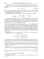
load (about 0.2 mm from the bottom end of the recess of the load plate). The oil
is used to transmit the AE signal from the load to the AE sensor.
The AE signal generated at the workpiece=plate interface is transmitted to
the AE sensor via workpieces and the load. After amplifying and filtering,
the raw AE signal with frequency between 0.1 and 1 MHz is collected and
data are recorded.
Ceramic workpieces (rings with 0.5’’ ID, 0.8’’ OD and 0.2’’ thickness) made
of Al
2
O
3
(Table 8.1) were lapped with diamond slurry on the single-side
lapping machine using a cast-iron plate and two conditioning rings.
Conditioning ring
Abrasive
slurry
Lapping plate
Load
Phenolic disk
Workpieces
PC
AE
AE signal
Main
amplifier
Pre-
amplifier
Oil
Lapping machine
FIGURE 8.1
Setup for the acquisition of the acoustic emission signal in the lapping process.
TABLE 8.1
Workpiece Material Properties
Material Al
2
O
3
—99.8%
Physical properties
Density (g=cm
3
) 3.96
Mechanical properties
Tensile strength (MPa) 310 (at 258C)
220 (at 10008C)
Modulus of elasticity (GPa) 366
Poisson ratio 0.22
Compressive strength (MPa) 3790 (at 258C)
1.929 GPa (at 10008C)
Ioan D. Marinescu / Handbook of Advanced Ceramics Machining 3837_C008 Final Proof page 196 6.10.2006 2:20am
196 Handbook of Advanced Ceramics Machining
Diamond abrasive was suspended in a water-based carrier and supplied by
a peristaltic pump at aflow rate of0.75 mL=min. The slurry was based on either
monocrystalline or polycrystalline diamond grains with 0.25 mm grit size.
During the lapping experiments, the following parameters were kept
constant:
.
Flow rate: 0.75 mL=min
.
Carrier type: water-based
.
Slurry concentration: 1.4 g=500 mL
The following parameters were varied:
.
Diamond type: monocrystalline and polycrystalline
.
Rotation of the lapping plate: 3, 6, and 9 rpm
.
Load: 380, 750, and 1200 g
.
Lapping time: 5, 15, 30, and 60 min
8.4 Experimental Results
8.4.1 Experimental Procedure
Three variables were considered in the experiments: (1) type of diamond:
monocrystalline (M) and polycrystalline (P); (2) rotation speed of the plate:
3, 6, and 9 rpm; (3) mass of the load: 380, 750, and 1200 g. The experimental
conditions are listed in Table 8.2.
In each experiment, AE signals were recorded and three parameters were
extracted from the AE signals: hits, counts, and energy. Each lapping
experiment lasted 60 min. The AE signals were sampled for about 30 sec
at the end of each lapping time: 5, 15, 30, and 60 min. The surface roughness
of the workpiece and the material removal rate (MRR) at each sampling
stage were measured.
8.4.2 Data Analysis
One objective of the experiments is to find the correlation between the AE
signal and surface roughness of workpieces. Counts, hits, and energy are
some of the important AE parameters in the AE signal analysis. Experimen-
tal data show that counts and hits vary irregularly with machining time. It is
not encouraged to try to find the correlation between AE counts, or hits, and
surface roughness of workpieces.
Ioan D. Marinescu / Handbook of Advanced Ceramics Machining 3837_C008 Final Proof page 197 6.10.2006 2:20am
AE Monitoring of the Lapping Process 197
The lapping process can be considered as a process with energy release.
A rough surface has high energy and a smooth surface has low energy. It is
reasonable to focus on its energy while checking the relationship between
the AE signal and surface quality of workpieces.
8.4.2.1 Energy Per Unit Time
Energy per unit time (EPT) can be obtained by dividing the total energy
recorded in a period of time by the duration of the recording. From Figure
8.2, it can be observed that the EPT decreases with time, showing the same
variation as surface roughness. Similar cases can also be observed in tests
carried out with both 6 rpm and 9 rpm. We can say that EPT has some kind
of correlation to the surface roughness. In these experiments, we cannot tell
if the EPT finally goes to a small constant as the surface roughness does.
One can see that increasing the load leads to higher values of the EPT,
which can be explained by higher AE activity since the abrasive grains are
pressed more against the workpiece. The same observation can be made for
increasing the plate rotation. One can say that an increase in the plate
rotation will yield smoother surfaces and higher values for EPT.
Taking into account the ideas mentioned above, one can say that the EPT
is a relevant AE parameter for monitoring the lapping process. It is sensitive
to the changes of load and plate rotation and can also monitor the roughness
TABLE 8.2
Experimental Conditions
Test Number Type of Diamond
Rotation Speed
of Plate (rpm) Mass of Load (g)
1 (M31) M 3 380
2 (M61) M 6 380
3 (M91) M 9 380
4 (M32) M 3 750
5 (M62) M 6 750
6 (M92) M 9 750
7 (M33) M 3 1200
8 (M63) M 6 1200
9 (M93) M 9 1200
10 (P31) P 3 380
11 (P61) P 6 380
12 (P91) P 9 380
13 (P32) P 3 750
14 (P62) P 6 750
15 (P92) P 9 750
16 (P33) P 3 1200
17 (P63) P 6 1200
18 (P93) P 9 1200
Ioan D. Marinescu / Handbook of Advanced Ceramics Machining 3837_C008 Final Proof page 198 6.10.2006 2:20am
198 Handbook of Advanced Ceramics Machining
resulting from the process conducted with certain values of the process
parameters. This can be explained by the correlation that exists between
the input parameters (load and plate rotation) and the output parameters,
one of which is the surface roughness. Owing to the above conclusion, the
next steps that were taken were focused on studying the relevance of EPT
for monitoring other parameters of the lapping process and the correlation
between them and this feature of the AE signal.
Figure 8.3 shows the variation in EPT function of the load used for
lapping for both monocrystalline and polycrystalline diamond grains. One
can draw the conclusion that EPT is sensitive to the type of abrasive that is
used for lapping since the values of this AE feature are different for mono-
and polycrystalline diamond grains. On the other hand, the different values
of EPT function of load can be explained by different mechanisms of
material removal. At very low values of load, the prevalent phenomenon
that occurs in the machining area is the rolling of abrasive grains on the
workpiece surface. This generates AE signals with low energy and is related
to low values of MRR. When using a heavier load (750 g) indentation,
scratching and plowing of abrasive grains on the workpiece surface occur.
All these phenomena generate AE signals with much higher energy because
of the friction between the abrasive grain and the workpiece material that is
involved in these mechanisms of material removal. By increasing the load
15,000
0.6
0.4
0.2
0
0.6
0.4
0.2
0
10,000
5,000
0
15,000
10,000
5,000
0
5
M61 M62 M63
M91 M92 M93 M91 M92 M93
M61 M62 M63
15 30 60
5 153060 5
15
30
60
5153060
Time (min)
Time (min) Time (min)
Time (min)
EPT
EPT
R
a
(µm)
R
a
(µm)
FIGURE 8.2
Energy released per unit time vs. time (left) and surface roughness vs. time (right).
Ioan D. Marinescu / Handbook of Advanced Ceramics Machining 3837_C008 Final Proof page 199 6.10.2006 2:20am
AE Monitoring of the Lapping Process 199
5000
n = 3 rpm; time = 5 min
n = 3 rpm; time = 30 min n = 3 rpm; time = 60 min
n = 3 rpm; time = 15 min
Monocrystal
Polycrystal
Monocrystal
Polycrystal
Monocrystal
Polycrystal
Monocrystal
Polycrystal
2500
ETP
ETP
ETP
ETP
0
5000
2500
0
5000
2500
0
5000
2500
0
380 750 1200 380 750 1200
Load (g)
380 750 1200
Load (g)
Load (g)
380 750 1200
Load (g)
FIGURE 8.3
Energy released per unit time vs. load at various lapping times.
30,000
20,000
10,000
0
30,000
20,000
10,000
0
30,000
30,000
20,000
10,000
0
20,000
10,000
0
ETP
ETP
Load = 1200 g; time = 15 minLoad = 1200 g; time = 5 min
Load = 1200 g; time = 60 min
Monocrystal
Polycrystal
Monocrystal
Polycrystal
Monocrystal
Polycrystal
Monocrystal
Polycrystal
369
n (rpm)
36369
369
9
n (rpm)n (rpm)
n (rpm)
ETP
ETP
Load = 1200 g; time = 30 min
FIGURE 8.4
Energy released per unit time vs. lapping plate rotation for various lapping times.
Ioan D. Marinescu / Handbook of Advanced Ceramics Machining 3837_C008 Final Proof page 200 6.10.2006 2:20am
200 Handbook of Advanced Ceramics Machining
used for lapping, the material removal mechanism is based mainly on brittle
fracture of the ceramic material. This generates AE signals with higher
energy than the rolling of the diamond abrasive grains on the workpiece
material, but lesser than the friction between them. From Figure 8.3, one
can conclude that EPT of the AE signal is sensitive and can be successfully
used for monitoring the type of abrasive and the prevalent mechanism of
material removal.
Similar conclusions can be drawn from Figure 8.4, which shows the
variation in the EPT function of the rotation of the lapping plate. It can
also be seen that the energy released is different for the two types of
diamond grains (monocrystalline and polycrystalline), as it is always higher
for the polycrystalline diamond. EPT is directly proportional with the rota-
tion of the lapping plate because at higher speeds all the phenomena
generated by the material removal mechanisms are more intense. One can
say that EPT is suitable also for monitoring the rotation of the lapping plate.
8.5 Conclusions
Among multiple features of the AE signal, it was found that the energy per
unit time is sensitive to the change in almost all lapping parameters and
thus it is suitable for monitoring this machining process. The energy of the
AE signal has some kind of correlation with the surface roughness of
workpieces, and this can be explained by the correlation between the
input and output parameters on one hand and between the input param-
eters and the AE signal on the other.
8.6 Remaining Work
For the AE system, a high-speed signal acquisition should be used to
monitor the lapping process in real time. Many experiments on work
parameters and the quality of lapped workpieces should be carried out to
confirm the conclusions drawn so far. Based on the experimental results,
a practical database can be established and used in real production. Some
new programs should be developed to efficiently analyze AE signals and
correlate them to surface integrity.
Ioan D. Marinescu / Handbook of Advanced Ceramics Machining 3837_C008 Final Proof page 201 6.10.2006 2:20am
AE Monitoring of the Lapping Process 201
Ioan D. Marinescu / Handbook of Advanced Ceramics Machining 3837_C008 Final Proof page 202 6.10.2006 2:20am
9
Effectiveness of ELID Grinding and Polishing
C.E. Spanu and I.D. Marinescu
CONTENTS
9.1 Introduction 204
9.1.1 Principle and Mechanism of ELID Grinding 204
9.1.2 Components of ELID Grinding System 206
9.1.3 Electrical Aspects of ELID Grinding 208
9.1.4 Characteristics of Grinding Wheel in ELID Applications 209
9.1.5 Structure and Properties of Ceramics 211
9.1.6 ELID Grinding Applied to Various Materials 211
9.1.7 ELID Grinding Applied to Ceramic Materials 212
9.2 Material Removal Mechanisms in Grinding of Ceramics
and Glasses 213
9.3 ELID Technique as Compared to Other Grinding Techniques 216
9.3.1 Summary of ELID Technology 216
9.3.2 Other In-Process Dressing Technologies 218
9.4 Applications of ELID Technique 218
9.4.1 ELID-Side Grinding 219
9.4.2 ELID Double-Side Grinding 220
9.4.3 ELID-Lap Grinding 222
9.4.4 ELID Grinding of Ceramics on Vertical Rotary Surface
Grinder 225
9.4.5 ELID Grinding of Ceramics on Vertical Grinding Center 226
9.4.6 ELID Grinding of Bearing Steels 230
9.4.7 ELID Grinding of Ceramic Coatings 234
9.4.8 ELID Ultraprecision Grinding of Aspheric Mirror 235
9.4.9 ELID Grinding of Microspherical Lenses 237
9.4.10 ELID Grinding of Large Optical Glass Substrates 237
9.4.11 ELID Precision Internal Grinding 237
9.4.12 ELID Grinding of Hard Steels 240
9.4.13 ELID Mirror-Like Grinding of Carbon Fiber Reinforced
Plastics 241
Ioan D. Marinescu / Handbook of Advanced Ceramics Machining 3837_C009 Final Proof page 203 6.10.2006 2:22am
203
9.4.14 ELID Grinding of Chemical Vapor Deposited Silicon
Carbide 242
9.5 Summary and Conclusions 242
References 244
9.1 Introduction
This chapter represents a state-of-the-art process in the domain of electro-
lytic in-process dressing (ELID) abrasives. The information enclosed repre-
sents a considerable effort of analysis and synthesis of more than 50 titles
from most relevant research published on this topic in the United States,
Japan, and western Europe for the last 10 years. A comprehensive descrip-
tion of the principle and characteristic mechanisms of ELID abrasion are
introduced. Specific features of each component of ELID grinding and
polishing system are described further. Next, an explanation of the success-
ful and wide application of ELID principles to ceramic grinding is fur-
nished. Most important, 14 applications of ELID principle to modern
abrasive processes are documented. The final summary and conclusions
represent a handy tool for rapid information on ELID abrasion.
9.1.1 Principle and Mechanism of ELID Grinding
ELID grinding is a grinding process that employs metal-bond-abrasive
wheels dressed in-process by the means of an electrolytic process. The
procedure continuously exposes new sharp abrasive grains to maintain
the material removal rate and continuously improve the surface roughness.
A key issue in ELID is to sustain the balance between the removal rate of
the bonding metal by electrolysis and the wear rate of diamond abrasive
particles (Chen and Li I & II, 2000). Whereas the diamond wearing rate is
directly related to grinding force, grinding conditions, and workpiece mech-
anical properties, the removal rate of the bonding metal depends on ELID
conditions such as voltage and current, and the gap between electrodes.
ELID grinding was first proposed by the Japanese researcher Hitoshi
Ohmori in 1990 (Ohmori and Nakagawa, 1990). Its most important feature
is that no special machine is required. Power sources from conventional
electrodischarge or electrochemical machines, as well as ordinary grinding
machines can be used for this method. ELID grinding is based on electro-
chemical grinding (ECG). The grinding wheel is dressed during the elec-
trolysis process, which takes place between the anodic workpiece and the
cathodic copper electrode in the presence of the electrolytic fluid. The main
Ioan D. Marinescu / Handbook of Advanced Ceramics Machining 3837_C009 Final Proof page 204 6.10.2006 2:22am
204 Handbook of Advanced Ceramics Machining
difference between ELID and ECG is that the purpose of ECG is to aid the
grinding by removing material from the workpiece, whereas the purpose of
ELID is to remove small amounts of material (few microns) from the bond of
the wheel.
The chemistry of the process is presented in Figure 9.1, whereas the
mechanism of the process is presented in Figure 9.2. The rate of bond metal
dissolution is highest at the metal–diamond interface particles; in other
words, the tendency of electrolytic dissolution is to expose the diamond
particles (Chen and Li I, 2000). In addition, the metal dissolution rate
increases with diamond concentration particles (Chen and Li I, 2000).
For a fixed gap and applied voltage, the current density does not change
much with the diamond concentration particles (Chen and Li I, 2000).
Hence, to maintain a constant rate of metal removal, the applied electric
field should be lower for a higher diamond concentration tool and vice
versa. This electric field concentration effect is greatly reduced when the
diamond particle is half exposed (Chen and Li II, 2000). This effect sharply
decreases from its highest value near the diamond–metal boundary to a
Fe − 2e → Fe
+2
Fe − 3e → Fe
+3
H
2
O → H
+
+ OH
−
Fe
+2
+ 2OH
−
→ Fe(OH)
2
Fe
+3
+ 3OH
−
→ Fe(OH)
3
↓
Fe
+2(3)
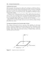
FIGURE 9.1
Dressing mechanism of ELID grinding. (From Qian, J., Ohmori, H., and Li, W., Int J Mach Tools
Manuf, 41, 193, 2001. With permission.)
Ioan D. Marinescu / Handbook of Advanced Ceramics Machining 3837_C009 Final Proof page 205 6.10.2006 2:22am
Effectiveness of ELID Grinding and Polishing 205
small value at a distance of the order of the diamond particle size (Chen and
Li II, 2000).
In a conventional grinding operation, the tool face is smooth and has no
protrusion of diamond particles after truing (Chen and Li II, 2000). Mech-
anical dressing opens up the tool face by abrasion with dressing stone,
which makes the grits to be exposed in the leading side and supported in
the trailing side. Laser and electrodischarge dressing opens up the tool face
by thermal damage, producing craters, microcracks, and grooves.
This induces a degradation of the diamonds because the diamond graph-
itizing temperature is relatively low, about 7008C. In electrochemical dress-
ing, grits are exposed by dissolving the surrounding metal bonds (Chen and
Li II, 2000).
9.1.2 Components of ELID Grinding System
The ELID system’s essential elements are a metal-bonded grinding wheel,
a power source, and an electrolytic coolant.
The metal-bonded grinding wheel is connected to the positive terminal of
the power supply with a smooth brush contact, whereas the fixed electrode
is connected to the negative pole. The electrode is made from copper that
has one-sixth of the wheel peripheral length and a width of 2 mm wider
than the wheel rim thickness. The gap between the wheel and the active
surface of the electrode is 0.1–0.3 mm and can be adjusted by mechanical
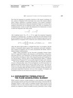
Fe
2+
Ion
1. Predressing started
4. Dressing stabilized
3. Dressing started
2. Predressing completed
Protruding
grain
Oxide (Fe
2
O
3
)
Scraped oxide
Oxide layer
removed
Worn grain
FIGURE 9.2
Mechanism of ELID. (From Stephenson, D.J., Veselovac, D., Manley, S., and Corbett, J., J Int Soc
Prec Eng Nanotechnol, 25, 336, 2001. With permission.)
Ioan D. Marinescu / Handbook of Advanced Ceramics Machining 3837_C009 Final Proof page 206 6.10.2006 2:22am
206 Handbook of Advanced Ceramics Machining
means. The stages of ELID grinding are presented in Figure 9.3; the preci-
sion truing of the micrograin wheel up to a runout of 2–4 mm (see Figure 9.4).
This is achieved through an electrical discharge method and it is carried out
to reduce the initial eccentricity below the average grain size of the wheel
and improve wheel straightness, especially when a new wheel is first used
or reinstalled.
1. The predressing process of the wheel by electrolytic means. The
protrusion of the abrasive grains is sought. The procedure is
performed at low speed and takes about 10–30 min.
2. The grinding process with continuous in-process dressing by elec-
trolytic means.
1. Wheel condition
on completion
of predressing
2. Wheel condition
after truing
(Predressing)
ELID cycle
ELID grinding
Constant grain
protrusion
obtained
4. Stabilized wheel
condition during
ELID grinding
3. Wheel condition
at start of
ELID grinding
Swarf easily
removed
Oxide layer removed
during grinding
Oxide
layer
FIGURE 9.3
Stages of ELID grinding. (From Bandyopadhyay, B.P. and Ohmori, H., Int J Mach Tools Manuf,
39, 839, 1999. With permission.)
Ioan D. Marinescu / Handbook of Advanced Ceramics Machining 3837_C009 Final Proof page 207 6.10.2006 2:22am
Effectiveness of ELID Grinding and Polishing 207
The conditions of electrolysis of the last two stages are different (as shown in
Figure 9.5 and presented in next paragraph) because of the change in the
wheel surface condition.
9.1.3 Electrical Aspects of ELID Grinding
The current characteristics (current value I and voltage E) are not constant
during a complete ELID procedure. When the predressing stage starts, the
active surface of the wheel has a high electrical conductivity; the current is
high while the voltage between the wheel and the electrode is low (vertical
line 1, in Figure 9.5). After several minutes, the bond material (cast iron) is
removed by electrolysis and transformed into Fe
2þ
. The ionized Fe will form
Fe(OH)
2
or Fe(OH)
3
according to the chemical transformations shown in
Figure 9.1.
The hydroxides further change into oxides Fe
2
O
3
through electrolysis.
This insulating oxide layer (20 mm thick) will reduce the electroconductivity
Infeed
CIB-cBN wheel
ELID power supply
Insulating material
Bronze tungsten carbide
Reciprocation
FIGURE 9.4
ELID truing mechanism. (From Qian, J., Ohmori, H., and Li, W., Int J Mach Tools Manuf, 41, 193,
2001. With permission.)
Ioan D. Marinescu / Handbook of Advanced Ceramics Machining 3837_C009 Final Proof page 208 6.10.2006 2:22am
208 Handbook of Advanced Ceramics Machining
of the wheel surface. The current decreases while the voltage increases
(vertical line 2, in Figure 9.5). Now, the grinding process can start with the
protruding abrasive grains. As the grains are worn, the insulating oxides’
layer is also worn. This increases the electroconductivity of the wheel so that
the electrolysis intensifies, generating a fresh insulating layer (vertical line 3,
in Figure 9.5). The protrusion of the grains remains constant.
The layer of oxide has a larger flexibility and a lower retention character-
istic as compared to the bulk bond material (Zhang et al., 2001a). Figure 9.6
depicts the characteristics of the oxide film thickness and different types of
grinding operations, rough or finish. For rough grinding, thin insulating
layer is required, whereas for mirror-like finish ELID grinding, a relatively
thick insulating layer is preferred.
An important aspect is the slight increase in the wheel diameter (or
thickness) during ELID grinding (Zhang et al., 2001a) because of the etched
and oxide layers’ formation. The increase in the relative wheel diameter
caused by insulator layer formation for different types of electrolytes is
presented in Figure 9.7.
9.1.4 Characteristics of Grinding Wheel in ELID Applications
The wheels for ELID applications are as follows:
Cast-Iron-Bonded Diamond. These wheels are manufactured by mixing
diamond abrasive, cast-iron powder or fibers, and a small amount of
carbonyl iron powder. The compound is shaped in the desired form
under a pressure of 6–8 t=cm
2
, and then sintered in an atmosphere of
ammonia. These wheels are not suited for continuous grinding for long
0
0
2
4
6
8
5
1
2
E
w
I
w
3
10
Electrical dressing ELID-grinding
Working voltage E
w
(V )
Working current E
w
(A)
15 20 25 30
0
20
40
60
80
min
FIGURE 9.5
Current characteristics during ELID grinding. (From Ohmori, H., Takahashi, I., and Bandyo-
padhyay, B.P., J Mat Proc Technol, 57, 272, 1996. With permission.)
Ioan D. Marinescu / Handbook of Advanced Ceramics Machining 3837_C009 Final Proof page 209 6.10.2006 2:22am
Effectiveness of ELID Grinding and Polishing 209
periods of time because (1) a tougher metal-bonded wheel has poor
dressing ability—both efficient and stable grinding cannot be achieved;
(2) high material removal rate frequently wears the abrasive imposing
frequent redressing procedures; (3) the wheels become embedded with
swarf during grinding of steels.
Bond
Abrasive grain
Thinner insulating layer
than abrasive protrusions
(a)
(b)
Insulating layer comparable to
abrasive protusions
FIGURE 9.6
Ideal wheel conditions for: (a) efficient grinding; (b) mirror-surface finish. (From Bandyopad-
hyay, B.P., Ohmori, H., and Takahashi, I., J Mat Proc Technol, 66, 18, 1997. With permission.)
−10 0
Depth of etched layer
Type-B
Type-A
AFG-M
Water
10 20
Depth of oxide layer
E
o
= 90 V
I
p
= 10 A,
T
on/off
= 2 µsec
10 min
30 µm
FIGURE 9.7
The depth of etched and oxide layers with different coolants. (From Zhang, C., Ohmori, H.,
Kato, T., and Morita, N., Prec Eng J Int Soc Prec Eng Nanotechnol, 25, 56, 2001a. With
permission.)
Ioan D. Marinescu / Handbook of Advanced Ceramics Machining 3837_C009 Final Proof page 210 6.10.2006 2:22am
210 Handbook of Advanced Ceramics Machining
Cast-Iron Fiber-Bonded Diamond (CIFB-D). These wheels provide high
grinding ratio and high material removal rates.
Cubic Boron Nitride (cBN). ELID grinding provides dressing of tough
metal-bonded wheels during grinding process. This in-process dress-
ing procedure will control the abrasive protrusions before and during
the grinding of ceramics.
9.1.5 Structure and Properties of Ceramics
Today, the U.S. structural ceramics market is estimated at over $3500
million as compared with $20 million in the year 1974, $350 million in
1990, and $865 million in 1995. The application of these materials can be
found in tool manufacturing, automotive, aerospace, electrical, electro-
nics industries, communications (fiber optics), medicine, and so on
(http:== www.acers.org=news= factsheets.asp).
The properties of ceramic materials, like all materials, are dictated by the
types of atoms present, the types of bonding between the atoms, and the
way the atoms are packed together (also known as the atomic scale struc-
ture). Most ceramics are compounded of two or more elements. The atoms
in ceramic materials are held together by a chemical bond. The two most
common chemical bonds for ceramic materials are covalent and ionic, which
are much stronger than in metallic chemical bond. That is why, in general,
metals are ductile, and ceramics are brittle.
The atomic structure primarily affects the chemical, physical, thermal,
electrical, magnetic, and optical properties. The microstructure can also
affect these properties but has its major effect on mechanical properties
and on the rate of chemical reaction. For ceramics, the microstructure can
be entirely glassy (glasses only), entirely crystalline, or a combination of
crystalline and glassy. In the last case, the glassy phase usually surrounds
small crystals, bonding them together.
The most important characteristics of ceramic materials are high hard-
ness, resistance to high compressive force, resistance to high temperature,
brittleness, chemical inertness, electrical insulator properties, superior elec-
trical properties, high magnetic permeability, special optic and conductive
properties, and so forth.
9.1.6 ELID Grinding Applied to Various Materials (Grobsky
and Johnson, 1998)
During the last 10 years, a number of publications have addressed the
merits of ELID when applied to bound abrasive grinding on brittle materials
such as BK-7 glass, silicon, and fused silica using fine mesh superabrasive
wheels. Many of these publications report that ELID grinding provides the
Ioan D. Marinescu / Handbook of Advanced Ceramics Machining 3837_C009 Final Proof page 211 6.10.2006 2:22am
Effectiveness of ELID Grinding and Polishing 211
ability to produce spectacular finishes on these brittle material surfaces,
with surface roughness on the nanometer scale (4–6 nm).
For some applications, this completely eliminates the need for loose
abrasive lapping or polishing. The application of ELID grinding to the
fabrication of large (150–250 mm in diameter) optical components is also
studied. Published data suggest that ELID grinding can be successfully
applied to substrates of this size regime.
9.1.7 ELID Grinding Applied to Ceramic Materials
Interest in advanced structural ceramics has increased significantly in recent
years because of their unique physical characteristics and significant
improvements in their mechanical properties and reliability.
Despite these advantages, the use of structural ceramics in various appli-
cations has not increased rapidly in part because of the high machining cost
of these materials. The cost of grinding may account for up to 75% of the
component cost for ceramics compared to 5%–15% for metallic components
(Ohmori et al., 1996).
The primary cost drivers in the grinding of ceramics are (1) low efficiency
resulting from the low removal rate; (2) high superabrasive wheel wear rate;
(3) long wheel dressing times (Ohmori et al., 1996).
The grinding process often results in surface fracture damage nullify-
ing the benefits of advanced ceramic processing methods (Bandyopadhyay
and Ohmori, 1999). These defects can significantly reduce the strength
and reliability of the finished component and are sensitive to grinding
parameters.
Stock removal rate increases with the increase in the number of passes,
higher stock removal rates obtained for stiffer machine tool (Zhang et al.,
2000a, b). For similar bond type grinding wheels, a larger stock removal rate
was obtained for larger grit sizes of the wheels (Zhang et al., 2000). Cast-
iron-bonded wheel has a larger stock removal rate, yet a lower grinding
force as compared with a vitrified bonded grinding wheel (Zhang et al.,
2000). Machine stiffness has little effect on residual strength of grounded
silicon under multipass grinding conditions; this can be attributed to the
effect of actual depth of cut of the wheel on workpiece strength (Zhang et al.,
2000). As the number of passes increases, the actual depth of cut approaches
the set depth of cut, which means that regardless of the machine tool
stiffness, the grinding force does not significantly alter the workpiece
strength (Zhang et al., 2000). In addition, more compressive residual stress
can be induced with a dull grinding wheel or with a grinding wheel of a
higher grit size, or with a wheel of stiff and strong bond material (Zhang
et al., 2000).
It was proved that a grinding wheel with a larger grit size presents a
larger damage depth to the grounded piece (Zhang et al., 2000). As the
Ioan D. Marinescu / Handbook of Advanced Ceramics Machining 3837_C009 Final Proof page 212 6.10.2006 2:22am
212 Handbook of Advanced Ceramics Machining
number of passes increases, the normal grinding force also increases (Zhang
et al., 2000). This increase in force is steeper in the beginning passes and
slows down as the number of passes increases, a phenomenon more evident
for a high stiffness machine tool (Zhang et al., 2000). Because of machine
tool deflection, the normal grinding force was smaller under lower machine
stiffness (Zhang et al., 2000). In addition, the normal force approaches
a limit value, regardless of the machine stiffness characteristics (Zhang
et al., 2000).
Therefore, ELID may not be beneficial to workpiece strength, although it
may be good for workpiece accuracy (Zhang et al., 2000). An interesting
aspect, yet controversial and not much studied, addresses the pulverization
phenomenon, which takes place in the surface layer of a ceramic workpiece
during grinding (Zhang and Howes, 1994). Surface pulverization makes
ceramic grains much smaller than those in the bulk, and makes the ground
surface look smoother.
9.2 Material Removal Mechanisms in Grinding
of Ceramics and Glasses
Generally, there are two approaches to investigate the mechanisms of abra-
sive–workpiece interactions during the grinding of ceramics (Bandyopad-
hyay et al., 1999):
1. Indentation–fracture mechanics approach, which models abrasive–
workpiece interactions by the idealized flaw system and deform-
ation produced by an indenter.
2. The machining approach involves measurement of forces coupled
with scanning electron microscope (SEM) and atomic force
microscope (AFM) observation of surface topography and grinding
debris.
The mechanism of material removal in ceramic machining is a combination
of microbrittle fracture and micro or quasiplastic cutting. The quasiplastic
cutting mechanism, typically referred to as ductile-mode grinding (pre-
sented in Figure 9.8), results in grooves on the surface that are relatively
smooth in appearance. By careful choice of grinding parameters and control
of the process, ceramics can be ground predominantly in this model. On the
other hand, the microbrittle fracture mechanism (shown in Figure 9.9)
results in surface fracture and surface fragmentation. Ductile regime grind-
ing of ceramics is preferred as no grinding flaws are introduced when the
machining is performed in this mode.
Ioan D. Marinescu / Handbook of Advanced Ceramics Machining 3837_C009 Final Proof page 213 6.10.2006 2:22am
Effectiveness of ELID Grinding and Polishing 213
As shown in Figure 9.8 and Figure 9.9, directly under the grit, a plastically
deformed zone can be noticed. Two principal crack systems are generated in
the process. These are median=radial cracks and lateral cracks. The brittle
mode removal of material is because of the formation and propagation of
these lateral cracks.
The specific depth at which a brittle–ductile transition occurs is a function
of the intrinsic material properties, such as plasticity and fracture, and is
given by (Bandyopadhyay and Ohmori, 1999):
Platic flow energy
Fracture energy
%
E
p
E
f
% d (9:1)
where d is the critical depth of cut.
Although it is not easy to observe these microcracks produced by grind-
ing, the depth of the median crack can be determined using the formula
(Inaski, 1988):
I
mc
¼ [0:034(cotan c)
2=3
{(E=H)
1=2
=Kc}]
2=3
F
2=3
(9:2)
where c is the indenter angle and F is the indentation load, E is the modulus
of elasticity, and Kc is the fracture toughness of the material. Therefore, the
Grinding
grain
L
Workpiece
Plastically
deformed
zone
FIGURE 9.8
A close-up view of the schematic of an abrasive grain removing material from a brittle
workpiece via ductile-regime grinding. (From Bandyopadhyay, B.P. and Ohmori, H., Int J
Mach Tools Manuf, 39, 839, 1999. With permission)
Ioan D. Marinescu / Handbook of Advanced Ceramics Machining 3837_C009 Final Proof page 214 6.10.2006 2:22am
214 Handbook of Advanced Ceramics Machining
depth of the median crack depends on the material properties, force, and
grinding grit shape. Indentation load (F) is determined by dividing the
grinding force with the number of active cutting edges on the contact area
between the grinding wheel and the workpiece.
This relationship would apply only above a threshold load of F
*
. The
critical load F
*
that will initiate crack can be determined by
F
Ã
¼
aKc
4
H
3
(9:3)
where a is the coefficient that depends on the indenter geometry.
In conclusion, crack size can be estimated theoretically by Equation 9.2
when the load exceeds a certain critical value, which can be determined by
Equation 9.3. The important parameters for the critical loads to propagate
subsurface damage are presented in Table 9.1 (Bandyopadhyay et al., 1999).
In achieving the plastic deformation process, the grain load for SiC and
Si
3
N
4
should be less than 0.2 N and 0.7 N, respectively. SEM and AFM
techniques permit to evaluate the surface and subsurface fracture damage.
Workpiece
Grinding
direction
Grinding
grain
Lateral
crack
Plastically
deformed
zone
L
Cl
FIGURE 9.9
Schematic of an abrasive grain removing material from a brittle workpiece via brittle-regime
grinding. (From Bandyopadhyay, B.P. and Ohmori, H., Int J Mach Tools Manuf, 39, 839, 1999.
With permission.)
Ioan D. Marinescu / Handbook of Advanced Ceramics Machining 3837_C009 Final Proof page 215 6.10.2006 2:22am
Effectiveness of ELID Grinding and Polishing 215
The micrographs look like in Figure 9.10 and Figure 9.11. From SEM and
AFM micrographs, one can assess the difference between the material
removal mechanism of brittle fracture and the ductile mode.
9.3 ELID Technique as Compared to Other Grinding
Techniques
9.3.1 Summary of ELID Technology
The ELID technology can provide in-process dressing of tough metal-bonded
superabrasive grinding wheels. With the application of this technology, the
metal-bonded wheels will be electrolytically dressed during the grinding
process. This in-process dressing will control the abrasive protrusion before
and during the grinding process. Significant reduction of grinding force has
been reported with the application of ELID. The specimens were ground both
in longitudinal and transverse directions. The basic construction of the ELID
grinding system for surface grinding is shown in Figure 9.12.
TABLE 9.1
Critical Loads Required to Propagate Subsurface Damage
Materials H [GPa] E [GPa] K
c
[MN=m
3=2
] F* [N]
SiC 24.5 392 3.4 0.2
Si
3
N
4
14 294 3.1 0.73
Source: From Bandyopadhyay, B.P., Ohmori, H., and Takahashi, I., Journal of
Materials Processing Technology, Vol. 66, 1997, pp. 18–24.
FIGURE 9.10
SEM micrographs: (a) #325; (b) #8000. (From Bandyopadhyay, B.P. and Ohmori, H., Int J Mach
Tools Manuf, 39, 839, 1999. With permission.)
Ioan D. Marinescu / Handbook of Advanced Ceramics Machining 3837_C009 Final Proof page 216 6.10.2006 2:22am
216 Handbook of Advanced Ceramics Machining
The ELID essential elements include a metal-bonded grinding wheel,
electrolytic power source, and electrolytic coolant. The most important
feature is that no special machine is required. The metal-bonded wheel is
connected to the positive terminal of a power supply with a smooth brush
contact, and a fixed electrode is made negative. The grinding wheel is
dressed because of the electrolysis phenomenon that occurs upon the sup-
ply of a suitable grinding fluid and an electric current.
In ELID process, protruding grains abrade the workpiece. As a result, the
grains and the oxide layer wear down. The wear of the oxide layer increases
the wheel’s electroconductivity. The current in the circuit will increase,
FIGURE 9.11
AFM micrographs: (a) #325; (b) #8000. (From Bandyopadhyay, B.P. and Ohmori, H., Int J Mach
Tools Manuf, 39, 839, 1999. With permission.)
Brush
CIFB wheel
Power
Coolant
Chuck
Work
Electrode
For ELID
FIGURE 9.12
Construction of ELID grinding system. (From Qian, J., Li, W., and Ohmori, H., Prec Eng, 24, 153,
2000a; Qian, J., Li, W., and Ohmori, H., J Mat Proc Technol, 105, 80, 2000b. With permission.)
Ioan D. Marinescu / Handbook of Advanced Ceramics Machining 3837_C009 Final Proof page 217 6.10.2006 2:22am
Effectiveness of ELID Grinding and Polishing 217
increasing the electrolysis as a result. Therefore, abrasive grains protrude
and the oxide layer is recovered. The electrical behavior is nonlinear because
of the formation of this insulating oxide layer.
9.3.2 Other In-Process Dressing Technologies
The concept of in-process dressing was promoted in its crude form by
Nakagawa (Nakagawa and Suzuki, 1986). The effects of in-process dressing
using a dressing stick were studied. The wheel is dressed at the beginning of
each stroke. Higher material removal rates were reported. An application of
this procedure to side grinding is difficult.
The concept of ECG was introduced by McGeough (1974). The electrolyt-
ically conductive metal-bonded wheel is the anode and a fixed graphite
stick is the cathode. The dressing process is an electrolytic phenomenon.
Wlech et al. (1993) employed this principle but they used sodium chloride
solution as the electrolyte, which is harmful for machine tools.
Another technique is based on electrical discharge phenomenon. The
electroconductive grinding wheel is energized with a small pulse current.
The flow of ions creates hydrogen bubbles in the coolant, creating an
increasing electric potential that, when becomes critical, generates a spark
that melts the material that clogs the wheel. This procedure does not pro-
vide protruding abrasive grains continuously, and is unsuitable for ultrafine
grinding of materials, especially with a micrograined-size grinding wheel.
Other nonconventional machining processes based on electrochemical
metal removal are electrochemical machining, ECG, electrochemical polish-
ing, and so on.
9.4 Applications of ELID Technique
ELID grinding was employed to process several types of materials like
ceramics, hard steels, ceramic glass, ceramic coatings, and so forth, with
various shapes (plane, cylindrical external and internal, spherical and
aspherical lenses, etc.) and dimensions. Various ELID applications and
their reference literature are listed here:
– ELID-side grinding (Zhang et al., 2000, 2001a); ELID double-side
grinding (Ohmori et al., 1996)
– ELID-lap grinding (Itoh and Ohmori, 1996; Itoh et al., 1998)
– ELID grinding of ceramics on vertical rotary surface grinder (Ohmori
et al., 1996)
– ELID grinding of ceramics on vertical grinding center (Bandyopadhyay
et al., 1997)
Ioan D. Marinescu / Handbook of Advanced Ceramics Machining 3837_C009 Final Proof page 218 6.10.2006 2:22am
218 Handbook of Advanced Ceramics Machining
– ELID grinding of bearing steels (Qian et al., 2000b)
– ELID grinding of ceramic coatings (Zhang et al., 2001a)
– ELID ultraprecision grinding of aspheric mirror (Moriyasu et al.,
2000)
– ELID grinding of microspherical lenses (Ohmori et al., 2001)
– ELID grinding of large optical glass substrates (Grobsky and Johnson,
1998)
– ELID precision internal grinding (Qian et al., 2000, 2001)
– ELID grinding of hard steels (Stephenson et al., 2001)
– ELID mirror-like grinding of carbon fiber reinforced plastics (CFRP)
(Park et al., 1995)
– ELID grinding of chemical vapor deposited silicon carbide (CVD-SiC)
(Zhang et al., 2001a)
9.4.1 ELID-Side Grinding (Zhang et al., 2000, 2001a)
ELID-side grinding setup is presented in Figure 9.13. ELID grinding was
compared with a conventional grinding operation applied to same work-
pieces in similar conditions. The oxide layer obtained during ELID grinding
changed the contact status between wheel and workpiece; practically, it was
a new bond wheel with a large-flexibility and contractile-ability bonded
Rotation
Workpiece
Rotation
Electrode
Brush
Wheel
Nozzle
Power soruce
−
+
FIGURE 9.13
Principle of ELID face grinding. (From Zhang, C., Kato, T., Li, W., and Ohmori, H., Int J Mach
Tools Manuf, 40, 527, 2000b. With permission.)
Ioan D. Marinescu / Handbook of Advanced Ceramics Machining 3837_C009 Final Proof page 219 6.10.2006 2:22am
Effectiveness of ELID Grinding and Polishing 219
wheel in place of the hard and high-retentive cast-iron bond. The conclu-
sions of the study were as follows:
– ELID double-side grinding can be employed to produce mirror-like
surface finish.
– Surface finish of the workpiece ground with ELID was better than that
of the workpiece ground conventionally.
– The material removal mechanism for ELID double-side grinding was
brittle-fracture mode for coarser wheels and ductile mode for finer
wheels.
– The material removal rate for ELID double-side grinding was slightly
higher as compared to conventional grinding.
– ELID grinding is highly recommended in precision grinding of hard-
brittle materials on conventional machine tools.
9.4.2 ELID Double-Side Grinding (Ohmori et al., 1996)
ELID double-side grinding setup is presented in Figure 9.14. A close-up
view of the same is given in Figure 9.15. The conclusions of the study were
presented in the following list:
– ELID grinding can be employed to produce mirror-like surface finish.
– Surface finish of the workpiece ground with ELID was slightly better
than that of the workpiece ground conventionally.
– Microscopic characteristics showed that the surface of the workpiece
ELID ground has fewer pits and sticking-outs, ductile-mode removal
was the main removal mechanism.
(a)
(b)
Electrode
−
+
Wheel
Press
Workpiece
Holder
FIGURE 9.14
Setup for ELID double-side grinding: (a) eccentric wheels; (b) concentric wheels. (From
Ohmori, H., Takahashi, I., and Bandyopadhyay, B.P., J Mat Proc Technol, 57, 272, 1996. With
permission.)
Ioan D. Marinescu / Handbook of Advanced Ceramics Machining 3837_C009 Final Proof page 220 6.10.2006 2:22am
220 Handbook of Advanced Ceramics Machining