Seamanship Techniques 2 Episode 5 pps
Bạn đang xem bản rút gọn của tài liệu. Xem và tải ngay bản đầy đủ của tài liệu tại đây (2.8 MB, 40 trang )
143Cargo and Hatchwork
Cleat
Canvas tarpaulin
Hatch boards
Ring bolt
for lashing
Not lower
than 10″
24″
supports
every 10″
Tyzack bar
Hatch coaming
Hatch coaming bracket (flanged)
Deck stringer vee’d and
welded to coaming
Freeboard deck
Transverse beam
Underdeck
girder
Underdeck
transverse
Deck
plate of
increased
scantling
Seam weld
Corner of hatchway
(at freeboard deck)
Forward
Underdeck girder
Butt weld
Queen
beam
Hatch
coaming
Locking
tongue
Wheels
Lanyard
Trackway
Hatchboards
Identity paint mark
Queen beam
King beam
Beam sockets
Battening bar
End coaming
Ring bolts
(for securing hatch tents) (or locking wires)
Side coaming
Cleats
Ring
bolt
Beam bolts
Tyzack bar
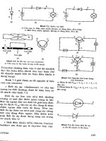
Figure 6.1 Conventional hatch.
Figure 6.2 Hatchway construction detail.
144 Seamanship Techniques
The cleating arrangement was such that once the tarpaulins had been
tucked, battening bars (steel) would be inserted on top and secured by
wooden wedges. It was important to secure the wedge correctly into the
cleat, or, when hammering home, the grain could split on the edge of
the cleat.
Finally tarpaulins and hatch boards were secured by locking bars or
locking wires over the complete hatch, to prevent the coverings from
blowing adrift and as an anti-theft device. Should the vessel’s freeboard
ever be lost, locking bars would also restrict the wooden hatch covers
from floating adrift, an important factor should the vessel be salvaged
after a sinking.
Tarpaulins were always laid with their seam edge athwartships and
away from the fore end of the vessel. This gave some protection from the
forward prevailing weather. Tarpaulins were also marked by eyelets to
indicate their newness, while hatch identity was established by the number
of knots placed in the securing lashing, a useful practice when several
hatch tarps were made up and stowed together.
Securing the Hatch for Sea
Once the cargo work has been completed, the beams positioned, and the
hatch boards replaced, the three tarpaulins will be stretched in the order
stated. Battening bars will then be forced between the cleats and the
tucked overlap of the two tarpaulins, and secured against movement by
wood wedges being hammered into the cleats. It is important that the
wedge is hammered in from the correct direction, namely with the long
side against the battening bar. The wedges should be hammered in by use
of a wooden mallet, hammering in the direction of the grain of the
wood. The flat end of the wedge is forced forward so as to be driven in
by any head-on weather, as opposed to being forced out.
The heavy iron locking bars are then secured across the top of the
hatch, being hooked under the upper lip of the coaming and drawn
together in the middle of the hatch by means of a worming screw
arrangement which may be locked by a padlock. The number of pairs of
locking bars to a hatch will ultimately depend on the length of the
hatchway and the number of hatch board sections as per rigging plan.
Each section of board should ideally be secured by at least one pair of
locking bars.
Hatch Tents
As is often the case, when the vessel is working cargo, rain may interrupt
the normal working operation. With the conventional hatch it proved a
laborious task to re-cover the hatchway every time a shower stopped
work, and so a tent, similar to a bell tent, was hoisted, usually from a
derrick head. The base area of the tent was sufficient to cover the total
hatchway area, and the tent was secured by tails to a wire stay running
around the hatch coaming. This method was a simple but time-saving
exercise, which prevented the cargo getting wet. The tent was easy to put
in place and could be just as easily cleared.
17. Booby hatch access to hold.
145Cargo and Hatchwork
With the efficient opening and closing of steel hatch covers today,
tents are not required for the modern vessel.
CONVENTIONAL HOLD
Construction
The hatchway entrance is a cut-away from the upper deck stringer
plates. The corners of the hatchway are cut on the round to provide
continuity of strength and prevent shearing stresses causing cracks
athwartships and bending forces causing cracks in the fore and aft line.
The corner turns of the hatchway are often fitted with reinforcing bars
to prevent loading and racking stresses (Figure 6.2).
Tank Top Ceiling
This is a wooden sheathing over the double bottom tank tops, usually in
way of the hatch, providing the tank tops with some protection from
wear and tear. The ceiling also assists ventilation and drainage of cargoes,
and with many cargoes relieves the necessity for laying of double dunnage.
This wood covering may come in one of two forms – either wide
flats, laid on bearers which leave space for liquids to drain off to the
bilges, or set close into a composition of cement and Stockholm tar.
When bulk cargoes are being regularly carried, the second method is
often employed, as the drainage spaces tend to become choked when the
first method is used.
It is not uncommon to see the most modern vessel with no tank top
ceiling at all, but in this case the tank top itself is normally protected by
having increased scantlings.
Turn of the bilge construction is shown in Figure 6.3.
Spar Ceiling
This may be in the form of horizontal or vertical wooden battens to
keep cargo off the steel work of the ship’s side. Contact between the shell
plate and the cargo tends to lead to excessive cargo sweat damage, and
to prevent this occurrence spar ceiling, sometimes referred to as cargo
battens, is secured in cleats throughout a cargo hold and ’tween deck.
Limber Boards
These are wooden boards similar to hatch boards that cover the bilge
bays, which are situated at the bottom sides of the lower holds. These
bays run the full length of the hold and should be regularly inspected for
their cleanliness. The boards are supported by the tank side brackets
between the floors and the frames.
Bilge Suctions – Strum Box
The bilge suction (Figures 6.4 and 6.5) is usually found in the aftermost
bay of the hold. Vessels normally trim by the stern, so that this aft siting
is best for drainage within the confines of the hatch. Scupper pipes tend
Shell plating
Side frame
Bracket on
frame
Spar ceiling
Tank side
bracket
Lightening hole
Bilge area
Non-return valve
Strum box
Margin plate Double bottom
CARGO HOLD
Wooden limber boards
Wood ceiling
Drain hole
Figure 6.3 Turn of bilge construction.
Figure 6.4 Bilge suction – strum box.
Limber boards
Margin
plate
Strum
box
Cement
Non-return
valve
Shell plate
Turn of the bilge
146 Seamanship Techniques
to drain direct from the afterpart of the ’tween deck into the bay containing
the strum box.
A non-return valve must be fitted clear of the strum, and in the more
modern vessels this valve is situated clear of the bilge area. The purpose
of the non-return valve is to prevent accidental run back from the
pumps, which may cause flooding in the hold. The suction end of the
pipe is kept clear of obstructions by the strum box arrangement built
about the pipe opening. This strum box is so constructed as to allow the
passage of water but not the passage of solids, which could interfere with
suction. The sides of the strum are either slotted or hinged to a framework
which will allow the box itself to be dismantled for cleaning and
maintenance. The whole bay containing the strum is covered by limber
boards.
General Cargo Vessel Deep Tanks
General arrangements vary especially in the securing of the deep tank
lids and the number of tanks constructed. It is normal to find deep tanks
in pairs or, if situated in a large hatch, then 2 × 2 pairs, to port and
starboard. They are extensively used for bulk cargoes such as grain or
chemicals but very often fitted with steam heated coils for the cariage of
such things as ‘Tallow’. They may also be used to take on extra ballast
when the vessel is in a light condition.
Hat box pumping arrangements are operated from the ship’s engine
room and the lines are fitted with a blanking off fitment when required.
Most systems allow for gravity filling and tanks are all fitted with air and
sounding pipes (Figure 6.5).
STEEL HATCH COVER
The more modern type of cargo vessel will be equipped with one of the
many types of steel hatch cover which are at present on the commercial
market (Figure 6.6). The many advantages with this style of cover by far
outweigh the disadvantages. They are fast in closing or opening, and the
latest versions are so labour-saving that one man could open up all the
Circulating
heating coils
(if fitted)
Side frame
Side
shell
plate
Grating over hat box to
allow passage of water
Hat box
Suction to
engine room
Figure 6.5 Deep tank suction – hat box.
Rubber gasket
Check wire
Bull wire
Hatch top wedge
Lead sheave
End coaming
Coaming hatch stays
Track
Wheel guide
Side dog
Eccentric wheel
Balancing roller
Side chains
Rising track
Figure 6.6 Single pull steel hatch cover.
147Cargo and Hatchwork
hatches of a ship in the time it takes to strip a single conventional hatch.
Their structure, being of steel, is extremely strong and generally forms a
flush surface in ’tween deck hatches providing ideal conditions for fork
lift truck work. Steel covers may be encountered not just at the weather
deck level but throughout a vessel, inclusive of ’tween decks. Hydraulic
operated covers are simple in operation, but should hydraulic fluid leak
at any time, cargo damage may result. The direct pull type must be
operated with extreme care, and all safety checks should be observed
prior to opening the chain-operated types.
Steel covers are illustrated in Figures 6.6 to 6.12 and Plates 18 to 23.
Opening Single Pull Macgregor Steel Hatch Cover
1. Release the side securing lugs, ensuring that they are correctly
stowed in flush position with the track.
2. Clear away any hatch top wedges between hatch sections.
3. Rig the check wire to the lug of the leading hatch section and
turn up the bight of the wire on to cleats or bitts.
4. Rig the bull wire so as to provide a direct pull to the winch from
the leading edge of the hatch cover.
5. Complete all work on top of the hatch covers. Check that the track
ways are clear of all obstructions, such as pieces of dunnage etc.
Figure 6.7 Securing steel covers. Cleating (dogging)
arrangement.
148 Seamanship Techniques
6. Turn down the eccentric wheels by use of bar levers, or by using
the jacks under the hatch cover sections.
7. Check that the locking pins are securely replaced in the eccentric
wheels once the wheels have been turned down to the track, in
such a manner that they will not slip out when the wheel rotates
or when the hatch is in the vertical stowed position.
8. Ensure that all personnel are aware that the hatch cover is about to
open, and that the stowage bay for the covers is empty and clear to
allow correct stowage of the sections.
9. Have a man standby to ease the check wire about the bitts, and,
just before hauling on the bull-wire, remove the locking pins at
the ends of the leading hatch section.
10. Heave away easily on the bull-wire once the locking pins are
removed, taking the weight of the leading hatch section.
11. Ease out on the check wire as the bull-wire heaves the hatch open
(Figure 6.6).
12. Once all hatch sections are in the stowed vertical position, the
bull-wire should not be removed until the securing chains from a
fixed point are in position to hold back the hatch sections in the
stowage bay area.
Screw cleat spanner
Cross-joint cleat [manual]
Eccentric wheel locking pin
[secures wheel in high or low position]
Eccentric wheel
[manually adjusted to suit high or low
positions in conjunction with jacking operation]
Balancing roller spindle
Jacking block
Rubber
Screw cleat
Balancing roller
Cover lifting jack [manual]
Eccentric wheel turning lever
[manual]
Junction piece assembly
Figure 6.8
Figure 6.9 Turning down eccentric wheels.
Pull on lever
(under or over motion depending
on hatch design)
Remove
locking pin
Insert bar
Packing
Trackway
Remove lug
Wheel free to run
Remove lever
Lug stowed
Replace locking pin
149Cargo and Hatchwork
18. Single pull Macgregor steel hatch covers in the
stowed upright position, showing fore and aft ends
of two separate hatches.
19. Steel hatch cover, with the locking pin seen in the
‘out’ position. The eccentric wheels are turned
down on to the trackway so as to raise the hatch.
The securing pin through the eccentric wheel is
clearly seen passing through at the level of the
bush. Side dogs are hanging vertically down under
the coaming, and lifting lugs, together with jacking-
up plates, are to be observed above the eccentric
wheel.
20. Chain pull steel hatch covers in the stowed upright
position.
150 Seamanship Techniques
22. Hydraulic folding Macgregor steel hatch covers
(weather deck), and hatchway showing a full cargo
of scrap metal.
23. Open hatchway showing exposed ’tween deck space.
Pontoon covers are stacked in the after end. Lower
hold contains general cargo. Spar ceiling is shown
exposed on the lower hold sides.
21. Rack and pinion horizontally stowed steel hatch
covers.
151Cargo and Hatchwork
Hinged sheave
Stowing arm
Wire pendant
Hauling eyeplate
Hinge
Panel 1
Panel 2
Panel 3
Wheel
Closing arm
Securing hook
Stowing arm pedestal Closing arm pedestal
7.8m clear
opening
2.87m slowage height
23.2m deck opening
8.5m deck opening
Hatch open showing typical
overall dimensions to suit
three rows of three 20ft
containers stowed through
the hatch.
N.B. All dimensions given are
typical and vary according
to individual installations.
Emergency operation can
be arranged
for all installations.
19.2m clear opening
Figure 6.10 Direct pull weatherdeck hatch covers (above).
Side rolling covers (right). Rack and pinion
drive, with hydraulic lifting and cleating.
Flexible hoses or
electric supply with quick
release coupling
Wheel
Link
mechanism
Cylinder
Trailing pair
Leading pair
Drag link
Hinges
Detachable stowage rail
Hydraulic pot-lift
Wheel-box
Optional : quick acting cleat
or hydraulic cleating
Self-engaging locking
at transverse cross-joint
Optional: hydraulic cleating
or quick acting cleat
Rack and pinion drive
Figure 6.11(a) Steel hatch covers, ’tween deck.
Trailing pair
Leading pair
Disconnected
Fixing bolts
Drag link
152 Seamanship Techniques
Folding
One pair
external cylinder
Cylinder
arrangement
Figure 6.11(b) Weather deck hydraulic folding hatch
covers.
Figure 6.12 Roll stowing covers – Rolltite. Originally
designed by Ermans and under manufacture
by Macgregor.
13. Clear away the check wire, coiling it down to one side of the
hatch. Do not attempt to detach the check wire from the lug of
the leading edge of the hatch.
GENERAL CARGO TERMINOLOGY
Bale Space
Internal volume measured to the inside edges of the Spar ceiling, beams,
tank top ceiling, and bulkhead stiffeners (spar ceiling is often referred to
as cargo battens).
Broken Stowage
Unfilled space between packages, this tends to be greatest when large
cases are stowed in the end holds, where the shape of the vessel fines off.
Deadweight Cargo
This cargo measures less than 40 cu.ft per ton (1.2 cu.m per tonne), and
freight is paid on the actual weight.
Dunnage
This is material used when stowing cargo to protect it from contact with
steelwork, other cargoes, or any possibly damaging influences. Tank tops
are usually covered with a double layer of dunnage wood, the bottom layer
running athwartships to allow drainage to bilges, and normally being
more substantial than the upper layer, e.g. 2 in. × 2 in (see Figure 6.13).
Additional dunnage is soft light wood, dry and free from stains, odour,
nails and large splinters. New timber should be free of resin and without
the smell of new wood. Materials also used for similar purpose are
matting, bamboo or waterproof paper.
Grain Space
This is the total internal volume of the compartment, measured from the
shell plating either side and from the tank top to underdeck. This measure-
ment is used for any form of bulk cargo that could completely fill the
space, an allowance being made for space occupied by beams and frames.
Figure 6.13 Use of dunnage.
Upper layer
Wood
laid approx.
6″
2′ to 3′
apart
1″
Bottom layer
Tank top
1″ = 2.5 cm
1′ = 30 cm
153Cargo and Hatchwork
Measurement Cargo
This is cargo measuring 40 cu.ft per ton (1.2 cu.m per tonne) or more.
The standard is used for comparatively light cargo on which freight is
paid on space occupied.
Stowage Factor
The volume occupied by unit weight, this is usually expressed in cu.ft/
ton or cu.m/tonne, no account being taken of broken stowage.
DUTIES OF JUNIOR CARGO OFFICER
1. Usually taking responsibility for either the forward or after holds.
2. Before cargo work begins, he should see that the spar ceiling is in
good order and in place, that holds and bilges have been cleaned
out, and that scuppers and bilge suctions have been tested.
3. Ensuring sufficient clean dunnage is allocated to each hold.
4. Checking that all cargo-handling gear is in correct working order
and correctly rigged.
5. Seeing that hold lighting is checked, and seen to be in good order.
6. Checking fire-smothering equipment.
7. Having ’tween-deck guard rails rigged, if necessary.
8. With conventional hatches, ensuring that any unshipped hatch
beams are secured against accidental dislodging.
9. Making hatch tents or other equivalent covering readily available
at short notice in the advent of bad weather.
10. Regularly checking on the holds to ensure that the cargo is handled
and stowed correctly, and on loading to ensure that adequate dunnage
is being used in a correct manner.
11. When discharging, searching the hold to ensure that no cargo is
left behind, which could lead to overcarriage.
12. Noting all times of starting and finishing cargo operations in the
deck log book, together with times of any stoppages.
13. Keeping a rough cargo plan showing cargo lots and their distribution,
together with port of destination, tonnage and general particulars.
14. Noting all damaged parcels of cargo when loading. Any damaged
parcels found on discharge should be landed in a safe place, and
agents and chief officer informed.
15. Ensuring hatchways are secured at the end of each working day.
16. Constantly watching for pilferage throughout all cargo operations.
17. Ensuring ban on smoking is observed in the holds and on the deck
areas.
18. Tallying special cargoes, such as mail, bullion etc. and providing
lock-up stowage.
19. Stowing dangerous cargo in accordance with the requirements of
the ‘IMDG code’ and/or IMO regulations.
20. Separating cargo of similar nature but for different ports by separation
cloths, paint or other appropriate separation mode.
154 Seamanship Techniques
21. Visiting transit shed ashore periodically to inspect stowage and
correct handling of cargo.
22. Seeing that fire precautions are observed throughout cargo operations.
HOLD PREPARATION
1. The compartment should be swept clean, and all traces of the
previous cargo removed. The amount of cleaning is dependent on
the nature of the previous cargo: some cargoes, such as coal, will
require the holds to be washed before the carriage of a general
cargo. Washing is always carried out after the compartment has
been swept. Drying time for washed compartments must be allowed
for, before loading the next cargo; this time will vary with the
climate, but two to three days must be expected.
2. Bilge areas should be cleaned and all ‘bilge suctions’ seen to be
working satisfactorily. All ‘holes’ in rose boxes should be clear to
allow the passage of water and the lines’ non-return valves seen to
be in a working condition. Should the bilges be contaminated
from odorous cargoes, it may become necessary to ‘sweeten’ them
by a wash of chloride of lime. This acts as a disinfectant as well as
providing a coating against corrosion.
3. The fire/smoke detection system should be tested and seen to
function correctly.
4. The holds drainage system and ’tween deck scuppers should be
clear and free from blockage.
5. Spar ceiling (cargo battens) should be examined and seen to be in
a good state of repair.
6. Hatch boards (conventional hatch) should fit correctly and be in a
good condition. Steel hatch covers should be inspected for their
watertight integrity about any joints. If hard rubber seals are fitted,
these should be inspected for deterioration.
7. Tarpaulins, if employed, should provide ample coverage and be of
good quality.
8. Hold fitments such as built-in lighting and guard rails should be
checked and seen to be in good order.
9. Soiled dunnage should be disposed of. New dunnage, clean
and dry, should be laid in a manner to suit the next cargo, if
needed.
10. Hold ventilation system should be operated to check fan conditions.
Additional for Special Cargoes
1. Grain. Limber boards should be plugged and covered with burlap.
This prevents grain blocking bilge suctions, while at the same time
allowing the passage of water.
2. Coal. Spar ceiling should be removed and covered (most bulk cargoes
require this).
3. Salt. Metalwork should be whitewashed.
155Cargo and Hatchwork
STOWAGE METHODS
Bagged Cargo (paper bags)
These should be stowed on double dunnage. Ideally the first layer should
be stowed athwartships on vessels equipped with side bilge systems.
Steelwork should be covered by brown paper or matting to prevent bags
making contact. Torn bags should be refused on loading. Canvas rope
slings should be made up in the hatchway centre to avoid dragging and
bursting bags. Hooks should never be used with paper bag cargoes.
When stowing, bag on bag stow is good for ventilation, whereas bag on
half bag is poor for ventilation but good for economical use of space.
Barrels
Stowed ‘bung’ uppermost on wood beds, in a fore and aft direction.
‘Quoins’ are used to prevent movement of the cargo when the vessel is
in a seaway. Barrels should never be stowed more than eight high.
Coal (bulk)
Check that bilge suctions are in working order and that limber boards
are tight fitting. Remove all spar ceiling, stow in the ’tween deck, and
cover with a tarpaulin or other similar protection. Plug ’tween deck
scuppers. Remove all dunnage and make arrangements for obtaining
temperatures at all levels if engaged on a long voyage. Ensure that the
coal levels are well trimmed and provide the compartment with surface
ventilation whenever weather conditions permit.
Copra
As it is liable to spontaneous combustion, it should be kept dry and clear
of steelwork surfaces, which are liable to sweat. Copra beetle will get
into any other cargoes which are stowed in the same compartment.
Cotton
Bales are liable to spontaneous combustion, so that the hold must be dry
and clean, free of oil stains etc. Adequate dunnage should be laid and all
steelwork covered to prevent contact with cargo. Wet and damaged bales
should be rejected at the loading port.
Hoses and fire appliances should be on hand and readily available
during the periods of loading, fire wires being rigged fore and aft.
Edible Oils
Deep tank stow, for which the tank must be thoroughly cleaned, inspected,
and a certificate issued.
Heating coils will be required, and these should be tested during the
period of preparation of the space. All inlets and outlets from the tank
should be blanked off. Shippers’ instructions with regard to carriage
temperatures should be strictly adhered to. A cargo log of these temperatures
should be kept. Extreme care should be taken on loading to leave enough
156 Seamanship Techniques
‘ullage’ for expansion of the oil during passage. Overheating should
never be allowed to occur, as damage to the oil will result.
Flour
Susceptible to damage from moisture or by tainting from other cargoes,
it should never be stowed with fruit, new timber or grain. Should a fire
occur during passage, ‘dust explosions’ are liable from this cargo.
Fruit
Usually carried in refrigerated spaces, especially over long sea passages, it
may also be carried chilled under forced ventilation. However, regular
checks should be made on ventilation system and compartment
temperatures. This cargo gives off CO
2
and will consequently require
careful ventilation throughout the voyage.
Glass (Crates)
Crates of glass should never be stowed flat, but on their edge, on level
deck space. Plate glass should be stowed athwartships and window glass
in the fore and aft line, each crate being well secured by chocks to
prevent movement when the vessel is at sea. Overstowing by other
cargoes should be avoided.
Vehicles
These should be stowed in the fore and aft line, on level deck space. They
should be well secured against pitching and rolling of the vessel by rope
lashings. Fuel tanks should be nearly empty. Close inspection should be
made at the point of loading, any damage being noted on acceptance.
CARGO HANDLING
Use of Snotters
Rope or wire snotters are in common use when general cargo is discharged.
Wire snotters are probably the most widely used, but care should be
taken that when using them as illustrated in Figure 6.14, the wire is not
allowed to slip along the surface of the steel. This possibility can be
eliminated by spreading the area of pressure by inserting a dunnage piece
between wire and cargo. Snotters should be secured on alternate sides,
passing eye through eye to provide stability to the load.
Use of the Bale Sling Strop
A bale sling strop is more commonly known as a sling or even just a rope
strop. it is an endless piece of rope whose ends have been joined by a
short splice, used extensively for the slinging of cases or bales, hence its
full title (see Figure 6.15).
Palletisation
This is a most convenient pre-package cargo-handling technique (Figure
Bundle of steel
bars
Dunnage piece
Figure 6.14 Use of snotters.
157Cargo and Hatchwork
6.16). Separate slings of cargo are made up before the vessel berths,
which speeds up turnround time, so saving the shipowner considerable
port costs. The cargo is generally stacked on wood pallets, which allows
easy handling by the use of fork lift trucks. The upper layer of cargo
packages are often banded or the full load may be covered by protective
polythene. This securing acts as a stabilising factor when the load is being
hoisted, as well as an anti-theft device while the pallet is being loaded,
stowed or discharged.
The slings are usually made of steel wire rope, having four legs secured
to a lifting ring. Each pair of wire slings holds a steel lifting bar, which
is used to lift the ends of the pallet and its cargo.
Each load is usually squared off, to reduce broken stowage within the
hold, especially so when the vessels are of a flush deck and square corner
construction. The pallets cause a certain amount of broken stowage, but
this has become an acceptable factor compared to costs of lengthy handling
procedures.
Cargo Nets
Fibre rope cargo nets (Figure 6.17) are in general use throughout the
marine industry and are extensively used for such cargoes as mail bags,
personal effects etc. where the extra strength and wear resistance of a
wire rope net is not required.
Wire rope cargo nets are designed for longer life, and are stouter than
fibre nets. They carry a bigger load with greater safety, and tend not to
distort under the most difficult conditions.
Fibre rope nets are generally of a knotted mesh, but may be woven.
The mesh of a wire rope net will contain a specially designed clip at
every cross, to provide reinforcement for the net as well as protecting the
wire from wear.
Timber Dogs
Timber dogs are used purely for the lifting of heavy logs. The weight of
the log causes the sharpened dogs to exercise an even greater grip when
inserted into the grain end of the timber. Extreme caution should be
observed with this method of lifting, to ensure that the point of the dog
is well embedded before starting the lift (see Figure 6.18).
Plate Clamps
If the construction of the plate will permit this method of lifting, then
it should be employed. Whether or not the construction of the plate
structure lends itself to the use of shackles and slings, or to plate clamps,
only one plate should be lifted at any one time.
When lifting with plate clamps (Figure 6.19), loads must not exceed
the marked capacity of the clamp, and the jaws must be as narrow as
possible for the plate thickness. Before lifting the plate, it should be
checked to ensure that it is properly gripped, and under no circumstances
should packing be used between the jaws and the plate. When two
Figure 6.15 Use of bale sling strop.
Four-legged wire or
chain sling
Lifting ring
Cargo
Wood
pallet
Lifting
bar
Figure 6.16 Use of pallets.
Figure 6.17 Cargo nets.
158 Seamanship Techniques
clamps are to be used, they should be inclined and secured in the line of
the sling, once the slack has been taken out of the slings.
Slinging Sheet Metal
In this operation plate dogs (Figure 6.20) or can hooks (Figure 6.21) can
be used. They are based on a similar holding operation, where the hooks
or dogs are tensioned together by a single chain sling (per pair) drawing
them tight about the load. The purpose of the adjustable spreader (Figure
6.20) is to prevent the two slings closing up and disturbing the stability
of the load.
Use of Chain Slings
Chain slings (Figure 6.22) are used for such heavy types of load as metal
castings. Extreme care should be observed with any load, but even more
so with a heavy lift, especially if chain slings are employed. There is a
tendency for links in the sling to kink inside each other, and if the sling
is pulled clear, the links or any kinks in the chain could cause the load
to tip, with possible dangerous consequences. It should be remembered
that a kink in a chain is a severe weakening factor and should be avoided
at all costs.
Timber bearers to provide a clear for the sling to be safely released
should be used when landing loads of this nature.
VENTILATION
Natural
This is the most common form of ventilation when cowls (Figure 6.23)
are trimmed into the wind to take in outside air, and trimmed back to
wind to allow the air circulation an exit from the hold. Fans may be
incorporated into this cowl ventilator system especially for the lower
hold regions where fans assist delivery and air extractors assist the exhaust
system. Cowls may also be fitted with manually operated closure flaps.
Forced
More recent developments in ventilating systems have led to air being
pre-dried before entering the hold. In some cases the temperature of the
air as well as its humidity may be controlled before entering the
compartment (Figure 6.24). This artificial or forced ventilation, has become
increasingly popular because, when properly used, it can almost prevent
any sweat damage to cargo.
REFRIGERATED CARGOES
Refrigerated cargoes include meat carcases, carton (packed) meat, fruit,
cheese, butter, fish and offal. Ships are specifically designed for their
carriage, with separate spaces in holds and ’tween decks, each fitted with
suitable insulation and individual control of ventilation. Ordinary general
cargoes may be carried in the spaces at other times, the temperature
being regulated accordingly for the type of cargo being carried.
Figure 6.18 Timber dogs.
Incorrect
Correct
Figure 6.19 Use of plate clamps.
Two chain slings
Lifting ring
Adjustable
spreader
Plate dogs
Lifts should be made with
the dogs fully loaded or
with suitable packing.
Figure 6.20 Use of plate dogs.
159Cargo and Hatchwork
Insulation around a compartment consists of either a fibreglass or
polystyrene type of packing over the steelwork of the vessel, with an
aluminium alloy facing. This insulation is comparatively fragile and requires
regular inspection and maintenance.
Cooling a compartment on modern vessels is achieved by circulating
pre-cooled air by means of fans. The air is cooled by an ordinary refrigeration
plant employing a refrigerant with the most practical qualities, namely, a
high thermaldynamic efficiency, low costs, low working pressure, low
volume non-toxicity, non-inflammability, non-explosivity and ready
availability from numerous sources.
Typical Refrigerants
Carbon dioxide (CO
2
). Non-poisonous, odourless, with no corrosive action
on metal. It has a low boiling point but a high saturated pressure.
Ammonia (NH
3
). Poisonous vapour, and therefore requires a separate
compartment of its own. It will corrode certain metals, e.g. copper. Has
a lower saturated pressure than CO
2
.
Freon (CCl
2
F
2
). Non-poisonous, non-corrosive, and has a low saturated
pressure. By far the most popular in modern tonnage.
An older style of reefer vessel had banks of brine-carrying pipes fitted
about the cargo compartment, but these are becoming increasingly rare
with the more up-to-date technology.
Properties of a Good Insulating Material
1. Odour. All material used should be odourless to prevent tainting of
cargoes.
2. Vermin. The material should be of such a nature, or so treated, that
it will not harbour vermin.
3. Moisture. The material should not readily absorb moisture.
Figure 6.21 Use of can hooks.
Timber bearers
Sling should not be pulled
from under load
or the load
is caused to
tip
Figure 6.22 Use of chain slings.
Cowl, covered with
protective gauze
Hand grips
Aperture – to accommodate
wooden plug once cowl is
removed (cowls are often
removed if bad weather is
expected). Plugs subsequently
covered by canvas.
Coaming – mild steel
welded construction
Ventilator shaft to hold
Figure 6.23 Cowl ventilators.
Ventilators
closed
Ventilators
open
Ventilators
closed
Ventilators
open
Ventilators
closed
Hold temperature
Outside air (Dewpoint temperature)
°F
74
72
70
68
66
64
62
60
58
1234567891011121314151617
Figure 6.24 Hold temperature and outside Dewpoint temperature graph.
160 Seamanship Techniques
4. Fire. Insulation material should be non-combustible, if possible,
but at least fire-resistant.
5. Cost. The financial outlay must be considered in view of the quantity
of material required.
6. Weight. Not as important as one might think for merchant vessels;
however, for ports with shallow water this would become a factor
for consideration.
7. Maintenance. Costs of installing and of maintaining the insulation
in good condition should be considered at the building/fitting-
out stage.
8. Settling. Value of the material is lost if, after settling, the air pockets
left will necessitate repacking.
9. Durability. Must be considered in comparison to the life of the
vessel.
10. Strength. A great advantage would be if the material was of such
quality as to withstand impact when loading or discharging.
Loading
Absolute cleanliness is required during the loading of refrigerated cargo,
and the following points should be observed:
1. The compartment should be cleaned of all debris and previous
cargo.
2. The deck should be scrubbed and the bulkheads and deck wiped
with a light disinfectant.
3. All bilges must be cleaned and bilge suctions tested.
4. ’Tween deck scuppers must be tested, together with all ‘U’ brine
traps.
5. Bilge plugs should be inspected and sealed. Cover plug over bilge
suction may be left off for the purpose of survey.
6. Fans must be checked for direction of air flow.
7. Bare steelwork must be insulated.
8. All odours must be cleared from the compartment.
9. All outside ventilation must be shut down.
10. Pre-cooling of the compartment must take place before the cargo
is received, times being noted in the cargo log or deck log book.
11. Before loading, the compartment should be surveyed. The surveyors’
comments together with the opening temperature of the chamber
should be recorded in the mate’s deck log book.
Any dunnage required for the cargo should be of a similar standard of
cleanliness as that of the compartment. All slings, chains etc. should also
be clean and pre-cooled in advance of cargo reception.
CARRIAGE OF GOODS IN DEEP TANKS
Deep tanks are cargo compartments that may be used for the carriage of
dry or liquid cargoes. They are usually found in dry cargo vessels at the
bottom of one of the holds, forming what would normally be the lower
hold portion of the hatch. Some vessels were built with deep tanks either
161Cargo and Hatchwork
side of the shaft tunnel (three-island type vessels), where they ran from
the midships machinery space, aft.
The openings into the tank are as follows:
1. Main lid.
2. Manhole entrance.
3. Ventilator trunkings.
4. Sounding pipe (usually in the hat box or well).
5. Ullage pipes.
6. Bilge suction line (into the hat box or well).
7. Ballast line.
8. CO
2
or steam smothering line (not always fitted).
9. Steam inlet pipes for heating coils.
When the tank is to be used for dry cargo, the following actions should be
carried out before loading the cargo:
(a) Open CO
2
or steam smothering lines, if fitted.
(b) Blank off ballast line.
(c) Check bilge suction and leave the bilge line open.
(d) Blank off steam inlet to heating coils. Coils may sometimes be
removed.
(e) Open or close ventilator trunks, as required.
When the tanks is to be used for liquid ballast, the following actions are
necessary:
(a)CO
2
or steam smothering lines should be blanked off.
(b) Bilge line opened.
(c) Steam inlet to heating coils sealed off.
(d) Ventilator trunks opened.
(e) Ballast bend fitted.
( f ) Main lid hard rubber packing should be inspected and checked for
deterioration. If found in good condition, the locking bolts should
be seen to be well screwed down to obtain even pressure on the
seal. Manholes should be treated in a similar manner.
Preparation of Deep Tanks to Receive Liquid Cargo
Tanks must be tested by a head of water equal to the maximum to which
the tank may be subjected, but not less than 2.44 m above the crown of
the tank. The rubber seal should be inspected for any signs of deterioration
about the perimeter of the main lid. Any rubber gaskets about the
inspection manholes should be seen to be in good order and to make a
good air/water seal.
After the tank has been tested, it should be thoroughly cleaned and
sealed. No rust spots or oil patches etc. should be visible. Hat boxes and
wells should be meticulously cleaned and sealed off, and ballast and CO
2
lines blanked off. Pressure valves should be fitted into ventilators and the
steam coils fitted and tested.
Once all preparations have been completed, the tank must be inspected
by a surveyor before loading and a certificate of the tank’s condition will
be issued.
162 Seamanship Techniques
TABLE 6.1 Cargoes carried in deep tanks
Product Specific gravity Cu.ft per tonne
Coconut oil 0.925–0.931 38.8
Palm oil 0.920–0.926 38.9
Palm nut 0.952 37.5
Tallow 0.911–0.915 39.4
Whale oil 0.880–0.884 40.76
CONTAINER TONNAGE
The container is probably the most common unit load system in operation
today. The introduction of standard size containers took place in the late
1950s, and the container trade has flourished ever since. Most cargoes are
shipped in container form, including heavy steel and liquids. Suitable
refrigerated containers may also be used for the carriage of frozen and
chilled foodstuffs, their plant power supply being connected to the vessel’s
main electrical source.
Containers of all sizes are generally loaded by a shore side gantry
crane, travelling the length of the quay on trackways. These cranes are
usually equipped with automatically controlled lifting mechanisms to
facilitate the lifting and loading of units. The jib section of the gantry
crane being lowered from the stowed elevated position after the vessel
has berthed alongside.
It would appear that in container operations one of the more sensitive
areas for accidents to ships’ personnel is ashore in the container stowage
area. Straddle trucks, often referred to as elephant trucks, used for the
transportation of containers from the park to the gantry crane, are driven
by drivers in a highly elevated position. The field of view is somewhat
restricted by the structure of the trucks, making the area extremely
dangerous for unauthorised personnel.
The disadvantage of the container trade is that an empty container
with no load to refill it becomes a liability, left at the wrong end of the
trade route. Consequently, the majority of container designed vessels will
at some part of the voyage carry to and fro some empty units. This means
a limited loss of revenue to the shipowner, though a necessity for the
continuation of the operation.
Ship’s officers should be aware that containers should be loaded in an
even manner, both athwartships and fore and aft, to maintain the stability
of the vessel. Not all containers are in a fully loaded condition, so that
the centre of gravity of the containers will vary. This will affect the final
centre of gravity of the vessel on completion. The problem is that unless
each container is opened up on loading, the ship’s personnel have only
the shore authorities’ word with respect to the weight and CG of the
container. However, it should be remembered that most container terminals
have means (weigh bridge) of checking container weights.
ROLL ON–ROLL OFF SYSTEM
Roll on–roll off (Ro Ro) methods of handling cargo have developed
163Cargo and Hatchwork
Bow visor in
raised position
Strong hinge
Hydraulic
ram
Hawse pipe and
anchor arrangement
set aft
Ramp
Figure 6.25 Visor type – bow door and ramp. All
openings are usually above the waterline
and the door is kept watertight by hard
rubber packing and hydraulic pressure on
closing.
24. Roll on–Roll off unit container cargo being loaded
over stern ramp of modern ferry vessel
from the original container idea of a door-to-door service for the shipping
customer. The concept is based on a quick turnround, making the delivery
not only fast and efficient but very economical. A larger type of vessel
has recently been constructed for the more lengthy voyage, with the
combined rapid turnround producing high yield profits.
Roll on–roll off ships are usually built with extensive fire-prevention
systems, including total CO
2
flooding to all garage spaces, automatic
sprinkler and/or water curtains, usually a foam installation, together with
conventional water hydrants. Fire precautions are maintained to a high
degree, with no smoking on vehicle decks, private cars to have limited
fuel in tanks etc. Regular drills and fire patrols are maintained, and a
smoke-detection system must be employed.
Construction of this type of vessel usually includes such special features
as longitudinally strengthened decks, clear of obstructions such as pillars
and spar ceiling; a forced ventilation fan system for the purpose of
clearing exhaust fumes; internal ramps to upper decks and/or cargo lifts
(electro/hydraulic) to lower levels; and a bow visor (Figure 6.25) with
vehicle ramps fore and aft, allowing access into main garage areas. Built-
in overhead lighting, welded struts for tyre grips, and anti-roll ship
stabilisers are also regular features of the Ro Ro trade.
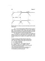
Securing Methods
All unit loads are disengaged from the loading tugmaster and secured by
a minimum of six chain lashings (40 ft unit). Additional lashings would
be secured to heavier or longer/wider loads. Each chain lashing is tensioned
and locked by a bar lever or loadbinder. Various ports have their own
systems: for example some ports do not cross the end lashings on units
but leave them just in the fore and aft line (see Figure 6.26).
Lashings are secured to the deck in ‘star insert’ or ‘star dome’ securing
points. A club foot is locked into the point while the other end of the
lashing hooks on to the lugs of the unit. The star insert points are flush
to the deck and are preferable to the raised dome securing points, which
is illustrated.
164 Seamanship Techniques
CARGO PLANS
General Cargo Vessels
A ship’s cargo plan shows the distribution as well as the disposition of all
parcels of cargo aboard the vessel. The plan is formulated usually from
the workbooks of the ‘deck officers’, a fair copy being produced before
departure from the final port of loading. This allows copies of the plan
to be made before the vessel sails. The copies are forwarded to agents at
ports of discharge to allow the booking and reservation of labour, as
appropriate.
The cargo plan should include relevant details of cargoes, i.e. total
quantity, description of package, bales, pallets etc., tonnage, port of discharge,
identification marks and special features if and when separated. The port
of discharge is normally ‘highlighted’ in one specific colour, reducing the
likelihood of a parcel of cargo being overcarried to the next port. Cargoes
which may have an optional port of discharge are often double-coloured
to the requirements of both ports.
The plan should be as comprehensive as space allows. Consequently,
abbreviations are a common feature, e.g. Liverpool as L’pool, 500 tonnes as
500t, cartons as ctns, cases as c/s, and heavy lift 120 tonnes as H/L, 120t.
Additional information, such as the following, generally appears on
most plans:
Name of the vessel.
Name of the Master.
List of loading ports.
List of discharging ports, in order of call.
Sailing draughts.
Tonnage load breakdown.
Hatch tonnage breakdown.
Voyage number.
Total volume of empty space remaining.
List of dangerous cargo, if any.
List of special cargo, if any.
Statement of deadweight, fuel, stores, water etc.
Details of cargo separations.
Recommended temperatures for the carriage of various goods.
Chief officer’s signature.
The plan provides at a glance the distribution of the cargo and shows
possible access to it in the event of fire or the cargo shifting. Its most
common function is to limit overcarriage and the possibility of short
delivery at the port of discharge. It also allows cargo operations, stevedores,
rigging equipment, lifting gear and so on to be organised without costly
delays to the ship.
Tankers
Tanker cargo plans are constructed on the same principle as plans for
general cargo ships. However, by the very nature of the cargo, it is only
Chain lashing
arrangement
Plan view unit load
Side elevation unit load
Back wheels
held by hand
brake
Stilt wheels
turned down
Portable trestle
accepts unit weight
for stowage and allows
motorised tug to
disengage.
Chain lashing tensioned
by loadbinders
Crossed lashings
prevent roll motion
of the unit as well
as pitch motions in
fore and aft line.
Figure 6.26 Ro Ro securing methods.
165Cargo and Hatchwork
25. Fore end view of tanker vessel at sea pipeline and
ventilation arrangements illustrated.
necessary to show disposition of the tank cargoes at one level. The plan
proves especially useful when a number of differing grades or types of
cargoes are to be loaded.
The plan should contain relevant information for the loading/discharge
officer and should include the following:
Grade of liquid.
Weight of cargo in the tank.
The ullage of the tank.
Volume and relative density at a specific temperature.
The carriage temperature.
Slack tanks’ identification.
Empty tanks’ identification.
Loaded draughts.
Deadweight.
Tonnage load breakdown.
Chief officer’s signature.
Colour schemes are employed usually to highlight the grade of cargo,
the danger from contamination being greater than that from overstowage
and overcarriage of cargo. It is not uncommon to see pipelines overprinted
on the plan, enabling cargo officers to see clearly which lines are to be
used for specific parcels of cargoes. This addition also lessens the risk of
contamination.
7
BOATWORK
Author’s note: mariners are advised that regulations refer to SOLAS and
the IMO publications. Member countries of the International Maritime
Organisation may have varying standards affecting their/our fleets imposed
by their/our authority, e.g. United Kingdom; Maritime and Coastguard
Agency.
General Requirements for Lifeboats
The 1983 amendments to the SOLAS convention of 1974 requires:
1. All lifeboats shall be properly constructed and have ample stability
in a seaway with sufficient freeboard when fully loaded with their
full complement of persons and equipment. All lifeboats shall have
rigid hulls and shall be capable of maintaining positive stability
when in an upright position in calm water, fully loaded as described,
and holed in any one location below the waterline, assuming no loss
of buoyancy material and no other damage.
2. Lifeboats should be of sufficient strength to:
(a) enable them to be safely lowered into the water when loaded
with their full complement and equipment;
(b) be launched and towed when the ship is making headway at a
speed of 5 knots in calm water.
3. Hulls and rigid covers shall be fire retardant or non-combustible.
4. Seating shall be provided on thwarts, benches or fixed chairs fitted
as low as practicable in the lifeboat and constructed so as to be
capable of supporting the number of persons each weighing 100 kg.
5. Each lifeboat shall be of sufficient strength to withstand a load
without residual deflection on removal of that load:
(a) In the case of boats with metal hulls, 1.25 times the total mass
of the lifeboat when loaded with its full complement of persons
and equipment.
(b) In the case of other boats, twice the total mass of the lifeboat
when loaded, as stated.
(Mariners should note that this requirement does not apply to
rescue boats.)
167Boatwork
6. The strength of each lifeboat when fully loaded and fitted with
skates or fenders where applicable, should be capable of withstanding
a lateral impact against the ship’s side at an impact velocity of at least
3.5 m/s and also a drop into the water from a height of at least 3 m.
7. The vertical distance between the floor surface and the interior of
the enclosure or canopy over 50 per cent of the floor area shall be:
(a) Not less than 1.3 m for a lifeboat permitted to accommodate
nine persons or less.
(b) Not less than 1.7 m for a lifeboat permitted to accommodate
24 persons or more.
(c) Not less than the distance as determined by linear interpolation
between 1.3 and 1.7 m for a lifeboat permitted to accommodate
between nine and twenty-four persons.
General Information Regarding Lifeboats
1. Access into Lifeboats
(a) Every passenger ship lifeboat shall be so arranged that it can be
rapidly boarded by its full complement of persons. Rapid
disembarkation shall also be possible.
(b) Every cargo ship lifeboat shall be so arranged that it can be
boarded by its full complement of persons in not more than 3
minutes from the time the instruction to board is given. Rapid
disembarkation must also be possible.
(c) Lifeboats shall have a boarding ladder that can be used on either
side of the lifeboat to enable persons in the water to board. The
lowest step of the ladder shall be not less than 0.4 m below the
lifeboat’s light waterline.
(d) The lifeboat shall be so arranged that helpless people can be
brought on board either from the sea or on stretchers.
(e) All surfaces on which persons might walk shall have a non-skid
finish.
2. Lifeboat Buoyancy
All lifeboats shall have inherent buoyancy or shall be fitted with
inherently buoyant material which shall not be adversely affected by
seawater, oil or oil products, sufficient to float the lifeboat with all
its equipment onboard when flooded and open to the sea. Additional
inherent buoyancy material equal to 280 N of buoyant force per
person shall be provided for the number of persons the lifeboat is
permitted to accommodate. Buoyant material, unless in addition to
that required above, shall not be installed external to the hull of the
boat.
3. Lifeboat Freeboard and Stability
All lifeboats, when loaded with 50 per cent of the number of
persons the lifeboat is permitted to accommodate seated in their
normal positions to one side of the centre line, shall have a freeboard