Intro to Naval Architecture 3E Episode 1 pptx
Bạn đang xem bản rút gọn của tài liệu. Xem và tải ngay bản đầy đủ của tài liệu tại đây (1.13 MB, 30 trang )
Introduction
to
Naval Architecture
This page intentionally left blank
Introduction
to
Naval
Architecture
Third Edition
E. C.
Tupper,
BSc, CEng, RCNC,
FRINA,
WhSch
OXFORD
AMSTERDAM BOSTON
LONDON
NEW
YORK
PARIS
SAN
DIEGO
SAN
FRANSISCO SINGAPORE SYNDEY TOKYO
Butterworth-Heinemann
An
imprint
of
Elsevier Science
Linacre
House, Jordan
Hill,
Oxford
OX2 8DP
First published
as
Naval
Architecture
for
Marine
Engineers,
1975
Reprinted 1978, 1981
Second edition published
as
Muckle's
Naval
Architecture,
1987
Third edition 1996
Reprinted
1997, 1999, 2000, 2002, 2002
Copyright
1996,
Elsevier
Science Ltd.
All
rights reserved.
No
part
of
this publication
may be
reproduced
in any
material
form
(including photocopying
or
storing
in any
medium
by
electronic means
and
whether
or not
transiently
or
incidentally
to
some other
use of
this publication) without
the
written
permission
of the
copyright holder except
in
accordance
with
the
provisions
of the
Copyright, Designs
and
Patents
Act
1988
or
under
the
terms
of a
licence issued
by the
Copyright Licencing
Agency
Ltd,
90
Tottenham Court Road,
London,
England
W1T
4LP.
Applications
for the
copyright holder's written permission
to
reproduce
any
part
of
this
publication should
be
addressed
to the
publishers.
British Library
Cataloguing
in
Publication
Data
A
catalogue record
for
this book
is
available
from
the
British
Library
ISBN
0
7506
2529
5
Library
of
Congress
Cataloguing
in
Publication
Data
A
catalogue record
for
this book
is
available
from
the
Library
of
Congress
For
information
on all
Butterworth-Heinemann publications
visit
our
website
at
www.bh.com
Composition
by
Genesis
Typesetting,
Rochester,
Kent
Printed
arid
bound
in
Great Britain
Contents
Preface
to the
third edition
vii
Acknowledgements
ix
1
Introduction
1
2
Definition
and
regulation
5
3
Ship
form
calculations
19
4
Flotation
and
stability
30
5 The
environment
81
6
Seakeeping
100
7
Strength
121
8
Resistance
173
9
Propulsion
209
10
Manoeuvring
252
11
Vibration, noise
and
shock
276
12
Ship
design
304
Appendix:
Units,
notation
and
sources
347
Index
353
V
This page intentionally left blank
Preface
to the
third
edition
One
definition
of
wisdom
is the
thoughtful
application
of
learning;
insight;
good
sense; judgement.
It can be
said that this book aims
to
contribute
to the
reader's
wisdom.
It
sets
out to
provide knowledge
of
the
fundamentals
of
naval architecture
so
that
the
reader
can
define
a
ship
form,
calculate
its
draughts
and
displacement
and
check
its
stability.
It
seeks
to
give
an
understanding
of
other aspects
of the
ship
such
as the
possible modes
of
structural failure
and its
manoeuvring
and
seakeeping performance.
It
presents information
on the
environ-
ment
in
which
the
ship
has to
operate,
and
describes
the
signs that
might
indicate pending trouble.
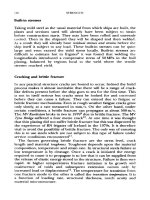
As
with
all
branches
of
engineering, naval architecture
is
changing
dramatically
as a
result
of
modern technology. Computers have made
a
big
impact
on the
design, construction
and
operation
of
ships.
New
materials
and
changing world economics
are
bringing
new
ship
types
into
commercial
use or
resulting
in
changes
in
more established types.
Greater emphasis
on
protection
of the
environment
has led to new
regulations
on
waste disposal
and the
design
of
ships
to
minimize
the
harmful
results
of oil
spillages
and
other accidents.
There
is now
greater
attention
to
safety
of
life
at
sea,
not
least
as a
result
of the
tragic
loss
of
life
in
passenger ferries such
as the
Estonia
and the
Herald
of
Free
Enterprise.
Because
of the
rate
of
change
in the
subject,
new
texts
are
required
not
only
by
those beginning
a
career
in the
profession
but
also
by
those
already
involved
who
wish
to
keep their knowledge up-dated. This book
is
intended only
as an
introduction
to
naval architecture.
It
sets
out to
educate those
who
need some knowledge
of the
subject
in
their
work,
such
as
sea-going engineers
and
those
who
work
in
design
offices
and
production organizations associated
with
the
maritime sector.
It
will
help those
who
aspire
to
acquire
a
qualification
in
naval architecture
up
to
about
the
incorporated engineer level. Most
major
design calcula-
tions
are, today, carried
out by
computer. However,
it is
vital
that
the
underlying
principles
are
understood
if
computer programs
are to be
applied intelligently.
It is
this understanding
which
this book sets
out to
provide
for the
technician.
vii
viii
PREFACE
Apart
from
ships,
many
are
involved
in the
exploitation
of
offshore
energy
resources, harvesting
the
riches
of the sea or in
leisure activities.
Leisure
is an
increasingly important sector
in the
market, ranging
from
small
boats
to
large yachts
and
ferries
and
even underwater passenger
craft
to
show
people
the
marvels
of
marine
life.
All
marine structures
must
obey
the
same basic
laws
and
remain
effective
in the
harsh marine
environment.
Many
of
those working
in
these
fields
will
have
had
their
basic
training
in a
more general engineering setting. This volume presents
the
essential knowledge
of
naval architecture they need
in a
form
which
they
should
find
easy
to
assimilate
as
part
of a
course
of
learning.
Those
who
are
already practitioners
will
find it
useful
as a
reference text.
Acknowledgements
Many
of the figures and
most
of the
worked examples
in
this
book
are
from
Muckle's
Naval
Architecture
which
is the
work this volume
is
intended
to
replace.
A
number
of figures are
taken
from
the
publications
of the
Royal Institution
of
Naval
Architects. They
are
reproduced
by
kind permission
of the
Institution
and
those concerned
are
indicated
in the
captions.
I am
very grateful
to my
son, Simon,
for
his
assistance
in
producing
the new
illustrations.
ix
This page intentionally left blank
1
Introduction
SHIPS
Ships
are a
vital element
in the
modern world. They
still
carry some
95
per
cent
of
trade.
In
1994 there were more than
80 000
ships each
with
a
gross tonnage
of 100 or
more, representing
a
gross tonnage
of
over
450
million
in
total. Although
aircraft
have displaced
the
transatlantic
liners,
ships
still
carry large numbers
of
people
on
pleasure cruises
and
on the
multiplicity
of
ferries operating
in all
areas
of the
globe. Ships,
and
other marine structures,
are
needed
to
exploit
the
riches
of the
deep.
Although
one of the
oldest
forms
of
transport, ships, their
equipment
and
their function,
are
subject
to
constant evolution.
Changes
are
driven
by
changing patterns
of
world trade,
by
social
pressures,
by
technological improvements
in
materials, construction
techniques
and
control
systems,
and by
pressure
of
economics.
As an
example,
technology
now
provides
the
ability
to
build much larger,
faster,
ships
and
these
are
adopted
to
gain
the
economic advantages
those
features
can
confer.
NAVAL
ARCHITECTURE
Naval
architecture
is a
fascinating
and
demanding discipline.
It is
fascinating
because
of the
variety
of floating
structures
and the
many
compromises
necessary
to
achieve
the
most
effective
product.
It is
demanding because
a
ship
is a
very
large capital investment
and
because
of the
need
to
protect
the
people
on
board
and the
marine
environment.
One has
only
to
visit
a
busy
port
to
appreciate
the
variety
of
forms
a
ship
may
take. This variation
is due to the
different
demands placed
on
them
and the
conditions under
which
they
operate.
Thus there
are
fishing
vessels ranging
from
the
small local boat operating
by
day,
to the
ocean going ships
with
facilities
to
deep
freeze
their catches.
There
are
vessels
to
harvest
the
other riches
of the
deep
- for
exploitation
of
l
2
INTRODUCTION
energy
sources,
gas and
oil,
and
extraction
of
minerals. There
are oil
tankers,
ranging
from
small coastal
vessels
to
giant supertankers. Other
huge ships carry bulk
cargoes
such
as
grain, coal
or
ore.
There
are
ferries
for
carrying passengers between ports
which
may be
only
a few
kilometres
or a
hundred apart. There
are the
tugs
for
shepherding
ships
in
port
or for
trans-ocean towing. Then there
are the
dredgers,
lighters
and
pilot boats without
which
the
port could
not
function.
In
a
naval port,
there
will
be
warships
from
huge
aircraft
carriers
through
cruisers
and
destroyers
to
frigates,
patrol boats, mine countermeasure
vessels
and
submarines.
Besides
the
variety
of
function
there
is
variety
in
hull
form.
The
vast
majority
of
ships
are
single hull
and
rely
upon their displacement
to
support their weight.
In
some applications multiple hulls
are
preferred
because they provide large deck areas without excessive length.
In
other
cases higher speeds
may be
achieved
by
using dynamic forces
to
support
part
of the
weight when under
way.
Planing
craft,
surface
effect
ships
and
hydrofoil
craft
are
examples.
Air
cushion
craft
enable shallow
water
to be
negotiated
and
provide
an
amphibious capability. Some
craft
will
be
combinations
of
these specialist
forms.
The
variety
is not
limited
to
appearance
and
function.
Different
materials
are
used
-
steel, wood, aluminium
and
reinforced plastics
of
various
types.
The
propulsion
system
used
to
drive
the
craft
through
the
water
may be the
wind,
but for
most
large
craft
is
some form
of
mechanical
propulsion.
The
driving power
may be
generated
by
diesels, steam turbine,
gas
turbine, some form
of
fuel
cell
or a
combination
of
these.
The
power
will
be
transmitted
to the
propulsion
device
through mechanical
or
hydraulic gearing
or by
using electric
generators
and
motors
as
intermediaries.
The
propulsor itself
will
usually
be
some
form
of
propeller, perhaps ducted,
but may be
water
or
air
jet.
There
will
be
many other systems
on
board
-
means
of
manoeuvring
the
ship, electric power generation, hydraulic power
for
winches
and
other cargo handling
systems.
A
ship
can be a
veritable floating township
with
several thousand
people
on
board
and
remaining
at sea for
several weeks.
It
needs
electrics,
air
conditioning, sewage treatment plant, galleys, bakeries,
shops, restaurants, cinemas, dance halls, concert halls
and
swimming
pools.
All
these,
and the
general layout must
be
arranged
so
that
the
ship
can
carry
out its
intended tasks
efficiently
and
economically.
The
naval
architect
has not
only
the
problems
of the
building
and
town
designer
but a
ship must float, move,
be
capable
of
surviving
in a
very
rough environment
and
withstand
a
reasonable level
of
accident.
It is
the
naval architect
who
'orchestrates'
the
design, calling upon
the
expertise
of
many
other professions
in
achieving
the
best compromise
between
many,
often
conflicting,
requirements.
The
profession
of
naval
INTRODUCTION
3
architecture
is a
blend
of
science
and
art.
Science
is
called upon
to
make
sure
the
ship goes
at the
intended speed,
is
sufficiently
stable
and
strong enough
to
withstand
the
rigours
of the
harsh environment
in
which
it
moves,
and so on. The art is in
getting
a
judicious blend
of the
many
factors involved
so as to
produce
a
product that
is not
only
aesthetically
pleasing
but is
able
to
carry
out its
function
with
maximum
effectiveness,
efficiency
and
economy.
Naval
architecture
is a
demanding profession because
a
ship
is a
major
capital investment that takes many years
to
create
and is
expected
to
remain
in
service
for
perhaps
twenty-five
years
or
more.
It
is
usually part
of a
larger transport system
and
must
be
properly
integrated
with
the
other elements
of the
overall
system.
The
geography
of, and
facilities
at,
some ports
will
restrict
the
size
of
ship
that
can be
accommodated
and
perhaps require
it to
carry special
loading
and
discharging equipment.
An
example
of
this
is the
container ship. Goods
can be
placed
in
containers
at the
factory where
they
are
produced. These containers
are of
certain standard dimen-
sions
and are
taken
by
road,
or
rail,
to a
port
with
specialized handling
equipment where they
are
loaded
on
board.
At the
port
of
destination
they
are
offloaded
on to
land
transport.
The use of
containers
means
that ships need spend
far
less time
in
port loading
and
unloading
and
the
cargoes
are
more secure. Port
fees
are
reduced
and the
ship
is
used
more
productively.
The
designer must create
the
best possible ship
to
meet
the
operator's needs.
In
doing this
he
must know
how the
ship
will
be
used
and
anticipate changes that
may
occur
in
those needs
and
usage over
the
years.
Thus
the
design must
be flexible.
History shows that
the
most
highly
regarded ships have been those able
to
adapt
with
time.
Most
important
is the
safety
of
ship, crew
and
environment.
The
design must
be
safe
for
normal operations
and not be
unduly
vulnerable
to
mishandling
or
accident.
No
ship
can be
absolutely
safe
and
a
designer must take conscious decisions
as to the
level
of
risk
judged acceptable
in the
full
range
of
scenarios
in
which
the
ship
can
expect
to find
itself. There
will
always
be a
possibility that
the
conditions catered
for
will
be
exceeded
and the risk of
this
and the
potential consequences must
be
assessed
and
only
accepted
if
they
are
judged
unavoidable
or
acceptable. Acceptable, that
is, by the
owner,
operator
and the
general public
and not
least
by the
designer
who has
ultimate responsibility. Even where errors
on the
part
of
others
have
caused
an
accident
the
designer should have considered such
a
possibility
and
taken steps
to
minimize
the
consequences.
For
instance,
in
the
event
of
collision
the
ship must have
a
good chance
of
surviving
or,
at
least,
of
remaining afloat long
enough
for
passengers
to be
taken
off
safely.
This brings
with
it the
need
for a
whole range
of
life
saving
4
INTRODUCTION
equipment.
The
heavy
loss
of
life
in the
sinking
of the
Estonia
in
1994
is
a sad
example
of
what
can
happen
when things
go
wrong.
Cargo ships
may
carry materials which would damage
the
environ-
ment
if
released
by
accident.
The
consequences
of
large
oil
spillages
are
reported
all too
often. Other chemicals
may
pose
an
even greater
threat.
The
bunker
fuel
in
ships
is a
hazard and,
in the
case
of
ferries,
the
lorries
on
board
may
carry
dangerous
loads.
Clearly
those
who
design, construct
and
operate
ships have
a
great responsibility
to the
community
at
large.
If
they
fail
to
live
up to the
standards expected
of
them
they
are
likely
to be
called
to
account
1
.
Over
the
years
the
safety
of
life
and
cargo
has
prompted governments
to
lay
down certain conditions that must
be met by
ships
flying
their
flag, or
using their ports. Because shipping
is
world wide there
are
also
international rules
to be
obeyed.
In the
case
of the
United Kingdom
the
government department
affected
is the
Department
of
Transport
and its
Marine
Safety
Agency. International control
is
through
the
International Maritime Organisation.
It is
hoped
that
these
few
paragraphs
have shown that naval
architecture
can be
interesting
and
rewarding.
The
reader
will
find the
various
topics discussed
in
more detail
in
later chapters where
the
fundamental
aspects
of the
subject
are
covered.
The
references
at the
end of
each chapter indicate sources
of
further reading
if it is
desired
to
follow
up any
specific topic.
A
more advanced
general
textbook
2
can
be
consulted. This
has
many more references
to
assist
the
interested
reader.
For
comments
on
references
see the
Appendix.
References
1.
Rawson,
K. J.
(1989) Ethics
and
fashion
in
design.
TRINA.
2.
Rawson,
K. J. and
Tupper,
E. C.
(1994)
Basic
Ship
Theory.
Fourth Edition,
Longman.
2
Definition
and
regulation
DEFINITION
A
ship's hull
form
helps determine most
of its
main attributes;
its
stability
characteristics;
its
resistance
and
therefore
the
power
needed
for a
given speed;
its
seaworthiness;
its
manoeuvrability
and its
load
carrying
capacity.
It is
important, therefore, that
the
hull shape should
be
defined
with
some precision
and
unambiguously.
To
achieve this
the
basic
descriptors used must
be
defined.
Not all
authorities
use the
same
definitions
and it is
important that
the
reader
of a
document checks
upon
the
exact definitions applying. Those used
in
this chapter cover
those used
by
Lloyd's Register
and the
United Kingdom
Ministry
of
Defence.
Most
are
internationally accepted. Standard units
and
notation
are
discussed
in the
Appendix.
The
geometry
A
ship's hull
is
three dimensional and, except
in a
very
few
cases,
is
symmetrical
about
a
fore
and aft
plane. Throughout this book
a
symmetrical
hull
form
is
assumed.
The
hull shape
is
defined
by its
intersection
with
three sets
of
mutually
orthogonal
planes.
The
horizontal planes
are
known
as
waterplanes
and the
lines
of
intersection
are
known
as
waterlines.
The
planes parallel
to the
middle line plane
cut
the
hull
in
buttock
(or
bow
and
buttock) lines,
the
middle line plane itself
defining
the
profile.
The
intersections
of the
athwartships planes define
the
transverse sections.
Three
different lengths
are
used
to
define
the
ship (Figure 2.1).
The
length between perpendiculars
(Ibp),
the
Rule
length
of
Lloyd's Register,
is
the
distance measured along
the
summer load waterplane (the design
waterplane
in the
case
of
warships)
from
the
after
to the
fore
perpendicular.
The
after
perpendicular
is
taken
as the
after
side
of the
rudder
post, where
fitted, or the
line passing
through
the
centreline
of
the
rudder pintles.
The
fore perpendicular
is the
vertical line through
the
intersection
of the
forward
side
of the
stem
with
the
summer load
waterline.
5
6
DEFINITION
AND
REGULATION
The
length overall
(loa)
is the
distance between
the
extreme points
forward
and aft
measured parallel
to the
summer
(or
design) waterline.
Forward
the
point
may be on the
raked stem
or on a
bulbous
bow.
The
length
on the
waterline (Iwl)
is the
length
on the
waterline,
at
which
the
ship happens
to be floating,
between
the
intersections
of the bow
and
after
end
with
the
waterline.
If not
otherwise stated
the
summer
load
(or
design) waterline
is to be
understood.
The
mid-point between
the
perpendiculars
is
called
amidships
or
midships.
The
section
of the
ship
at
this point
by a
plane normal
to
both
the
summer waterplane
and the
centreline plane
of the
ship
is
called
the
midship section.
It may not be the
largest section
of the
ship. Unless
otherwise defined
the
beam
is
usually quoted
at
amidships.
The
beam
(Figure 2.2) most commonly
quoted
is the
moulded beam,
which
is the
greatest distance between
the
inside
of
plating
on the two
sides
of the
ship
at the
greatest width
at the
section chosen.
The
breadth extreme
is
measured
to the
outside
of
plating
but
will
also take account
of any
overhangs
or flare.
The
ship
depth
(Figure 2.2) varies along
the
length
but is
usually
quoted
for
amidships.
As
with
breadth
it is
common
to
quote
a
moulded
depth,
which
is
from
the
underside
of the
deck plating
at the
ship's
side
to
the top of the
inner keel plate. Unless otherwise specified,
the
depth
is
to the
uppermost continuous deck. Where
a
rounded
gunwhale
is
fitted the
convention
used
is
indicated
in
Figure 2.2.
Sheer
(Figure 2.1)
is a
measure
of how
much
a
deck
rises
towards
the
stem
and
stern.
It is
defined
as the
height
of the
deck
at
side above
the
deck
at
side amidships.
DEFINITION
AND
REGULATION
7
Figure
2,2
Breadth
measurements
Camber
or
round
of
beam
is
defined
as the
rise
of the
deck
in
going
from
the
side
to the
centre
as
shown
in
Figure 2.3.
For
ease
of
construction camber
may be
applied only
to
weather decks,
and
straight line camber often replaces
the
older parabolic curve.
The
bottom
of a
ship,
in the
midships region,
is
usually
flat but not
necessarily horizontal.
If the
line
of
bottom
is
extended
out to
intersect
the
moulded breadth line (Figure 2.3)
the
height
of
this intersection
above
the
keel
is
called
the
rise
of
floor or
deadrise.
Many
ships have
a flat
keel
and the
extent
to
which this extends athwartships
is
termed
the
flat
of
keel
or
flat
of
bottom.
In
some ships
the
sides
are not
vertical
at
amidships.
If the
upper
deck
beam
is
less than that
at the
waterline
it is
said
to
have
tumble home,
the
value being half
the
difference
in
beams.
If the
upper deck
has a
greater beam
the
ship
is
said
to
have
flare.
All
ships have
flare at a
distance
from
amidships.
Figure
2.3
Section measurements
8
DEFINITION
AND
REGULATION
The
draught
of the
ship
at any
point along
its
length
is the
distance
from
the
keel
to the
waterline.
If a
moulded
draught
is
quoted
it is
measured
from
the
inside
of the
keel plating.
For
navigation purposes
it
is
important
to
know
the
maximum draught. This
will
be
taken
to the
bottom
of any
projection below keel such
as a
bulbous
bow or
sonar
dome.
If a
waterline
is not
quoted
the
design waterline
is
usually
intended.
To aid the
captain draught marks
are
placed near
the bow
and
stern
and
remote reading devices
for
draught
are
often provided.
The
difference between
the
draughts
forward
and aft is
referred
to as
the
trim.
Trim
is
said
to be by the bow or by the
stern
depending upon
whether
the
draught
is
greater forward
or aft
Often draughts
are
quoted
for the two
perpendiculars. Being
a flexible
structure
a
ship
will
usually
be
slighdy curved
fore
and
aft. This curvature
will
vary
with
the
loading.
The
ship
is
said
to
hog
or sag
when
the
curvature
is
concave
down
or up
respectively.
The
amount
of hog or sag is the
difference
between
the
actual draught amidships
and the
mean
of the
draughts
at
the
fore
and
after
perpendiculars.
Freeboard
is the
difference between
the
depth
at
side
and the
draught,
that
is it is the
height
of the
deck above
the
waterline.
The
freeboard
is
usually
greater
at the bow and
stern than
at
amidships. This helps
create
a
drier
ship
in
waves.
Freeboard
is
important
in
determining
stability
at
large angles (See Chapter
4).
Representing
the
hull form
The
hull
form
is
portrayed graphically
by the
lines
plan
or
sheer
plan
(Figure
2.4). This shows
the
various curves
of
intersection between
the
hull
and the
three sets
of
orthogonal planes. Because
the
ship
is
symmetrical,
by
convention
only
one
half
is
shown.
The
curves showing
the
intersections
of the
vertical fore
and aft
planes
are
grouped
in the
sheer
profile,
the
waterlines
are
grouped
in the
half
breadth
plan;
and the
sections
by
transverse planes
in the
body
plan.
In
merchant ships
the
transverse sections
are
numbered
from
aft to
forward.
In
warships they
are
numbered
from
forward
to aft
although
the
forward half
of the
ship
is
still,
by
tradition, shown
on the
right hand side
of the
body plan.
The
distances
of the
various intersection points
from
the
middle line plane
are
called
offsets.
Clearly
the
three sets
of
curves making
up the
lines plan
are
inter-
related
as
they
represent
the
same three dimensional body. This inter-
dependency
is
used
in
manual fairing
of the
hull form,
each
set
being
faired
in
turn
and the
changes
in the
other
two
noted.
At the end of
the
iteration
the
three sets
will
be
mutually compatible. Fairing
is
usually
now
carried
out by
computer. Indeed
the
form
itself
is
often
Figure
2.4
Lines
plan
10
DEFINITION
AND
REGULATION
generated directly
from
the
early design processes
in the
computer,
Manual fairing
is
done
first in the
design
office
on a
reduced
scale
drawing.
To aid
production
the
lines used
to be
laid off,
and re-
faired,
full
scale
on the floor of a
building known
as the
mould
loft.
Many
shipyards
now use a
reduced scale,
say
one-tenth,
for use in the
building process.
For
computer designed ships
the
computer
may
produce
the set of
offsets
for
setting
out in the
shipyard
or,
more
likely,
it
will
provide computer tapes
to be
used
in
computer aided
manufacturing
processes.
In
some ships, particularly carriers
of
bulk cargo,
the
transverse
cross section
is
constant
for
some fore
and aft
distance
near
amidships. This portion
is
known
as the
parallel
middle
body.
Where
there
are
excrescences
from
the
main hull, such
as
shaft
bossings
or a
sonar dome, these
are
treated
as
appendages
and
faired
separately.
Hull characteristics
Having
defined
the
hull
form
it is
possible
to
derive
a
number
of
characteristics which have significance
in
determining
the
general
performance
of the
ship.
As a floating
body,
a
ship
in
equilibrium
will
displace
its own
weight
of
water. This
is
explained
in
more detail
in
Chapter
4.
Thus
the
volume
of the
hull below
the
design
load
waterline must represent
a
weight
of
water equal
to the
weight
of the
ship
at its
designed load. This
displacement,
as it is
called,
can be
defined
as:
D=pg
where
p - the
density
of the
water
in
which
the
ship
is floating
g
- the
acceleration
due to
gravity
V
= the
underwater volume
It
should
be
noted that displacement
is a
force
and
will
be
measured
in
newtons.
For flotation,
stability,
and
hydrodynamic performance generally,
it is
this displacement,
expressed
either
as a
volume
or a
force, that
is of
interest.
For
rule
purposes
Lloyd's Register also
use a
moulded
displacement
which
is the
displacement within
the
moulded lines
of the
ship between
perpendiculars.
It
is
useful
to
have
a
feel
for the fineness of the
hull form. This
is
provided
by a
number
of
form
coefficients
or
coefficients
of fineness.
These
are
defined
as
follows,
where
V is the
volume
of
displacement:
DEFINITION
AND
REGULATION
11
where
L
pp
is
length between perpendiculars
B
is the
extreme breadth underwater
T is the
mean draught.
Corresponding
to
their moulded displacement Lloyd's Register
use a
block
coefficient
based
on the
moulded displacement
and the
Rule
length.
This
will
not be
used
in
this
book.
where
A
w
is
waterplane area
L
WL
is the
waterline length
B
is the
extreme breadth
of the
waterline.
Midship
section
coefficient,
C
M
where
A
M
is the
midship section area
B
is the
extreme underwater breadth amidships.
Longitudinal
prismatic
coefficient,
Cp
It
will
be
noted that these
are
ratios
of the
volume
of
displacement
to
various
circumscribing rectangular
or
prismatic blocks,
or of an
area
to
the
circumscribing rectangle.
In the
above,
use has
been
made
of
displacement
and not the
moulded dimensions. This
is
because
the
coefficients
are
used
in the
early design stages
and the
displacement
dimensions
are
more
likely
to be
known. Practice varies, however,
and
moulded
dimensions
may be
needed
in
applying some classification
societies' rules.
The
values
of
these
coefficients
can
provide
useful
information about
the
ship form.
The
block coefficient indicates whether
the
form
is
full
or fine and
whether
the
waterlines
will
have large
angles
of
inclination
to
the
middle line
plane
at the
ends.
The
angle
at the bow is
termed
the
angle
of
entry
and
influences resistance.
A
large value
of
vertical
prismatic
coefficient
will
indicate body sections
of
U-form,
a low
value
12
DEFINITION
AND
REGULATION
will
indicate
V-sections.
A low
value
of
midship section
coefficient
indicates
a
high rise
of
floor
with
rounded bilges.
It
will
be
associated
with
a
higher prismatic
coefficient.
Displacement
and
tonnage
Displacement
A
ship's
displacement
significandy
influences
its
behaviour
at
sea.
Displacement
is a
force
and is
expressed
in
newtons
but the
term
mass
displacement
can
also
be
used.
Deadweight
Although
influencing
its
behaviour, displacement
is not a
direct
measure
of a
ship's carrying
capacity,
that
is, its
earning power.
To
measure capacity
deadweight
and
tonnage
are
used.
The
deadweight,
or
deadmass
in
terms
of
mass,
is the
difference
between
the
load displacement
up to the
minimum permitted
freeboard
and the
lightweight
or
light displacement.
The
lightweight
is
the
weight
of the
hull
and
machinery
so the
deadweight includes
the
cargo,
fuel,
water,
crew
and
effects.
The
term
cargo
deadweight
is
used
for
the
cargo alone.
A
table
of
deadweight against draught,
for
fresh
and
salt
water,
is
often
provided
to a
ship's master
in the
form
of a
deadweight
scale.
Tonnage
Ton
is
derived
from
tun,
which
was a
wine
cask.
The
number
of
tuns
a
ship
could carry
was a
measure
of its
capacity. Thus tonnage
is a
volume
measure,
not a
weight measure,
and for
many years
the
standard
ton was
taken
as 100
cubic
feet.
Two
'tonnages'
are of
interest
to the
international community
- one to
represent
the
overall
size
of a
vessel
and one to
represent
its
carrying capacity.
The former
can
be
regarded
as a
measure
of the
difficulty
of
handling
and
berthing
and the
latter
of
earning ability. Because
of
differences
between
systems adopted
by
different countries,
in
making allowances
say
for
machinery spaces, etc., there were many anomalies. Sister ships
could have
different
tonnages merely
because
they
flew
different
flags.
It
was to
remove these anomalies
and
establish
an
internationally
approved system that
the
International Convention
on
Tonnage
Measurement
of
Ships,
was
adopted
in
1969
1
.
It
came into force
in
1982
and
became
fully
operative
in
1994.
The
Convention
was
held
under
the
auspices
of the
International Maritime Organisation
to
DEFINITION
AND
REGULATION
13
produce
a
universally recognised
system
for
tonnage measurement.
It
provided
for the
independent calculation
of
gross
and net
tonnages
and has
been discussed
in
some detail
by
Wilson
2
.
The two
parameters
of
gross
and net tonnage are
used.
Gross
tonnage
is
based
on the
volume
of all
enclosed spaces.
Net
tonnage
is the
volume
of
the
cargo space plus
the
volume
of
passenger spaces multiplied
by a
coefficient
to
bring
it
generally into line
with
previous calculations
of
tonnage.
Each
is
determined
by a
formula.
Gross
tonnage
(G7)
=
47
V
=
total
volume
of all
enclosed spaces
of the
ship
in
cubic
metres
k
1
=
0.2 +
0.02
log
10
V
V
c
=
total volume
of
cargo spaces
in
cubic metres
K
2
= 0.2 +
0.02
log
10
V
c
D
=
moulded depth amidships
in
metres
T =
moulded draught amidships
in
metres
N
1
=
number
of
passengers
in
cabins
with
not
more than
eight berths
N
2
=
number
of
other passengers
N
1
+
N
2
=
total number
of
passengers
the
ship
is
permitted
to
carry.
In
using these
formulae:
(1)
When
N
1
+ N
2
is
less than
13, N
1
and N
2
are to be
taken
as
zero.
(2)
The
factor
(4T/3D)
2
is not to be
taken
as
greater than
unity
and the
term
K
2
V
C
(4T/3D)
2
is not to be
taken
as
less than
0.25GT.
(3)
NT is not to be
less than
0.30GT.
(4)
All
volumes included
in the
calculation
are
measured
to the
inner
side
of the
shell
or
structural
boundary
plating,
whether
or not
insulation
is
fitted,
in
ships constructed
of
metal.
14
DEFINITION
AND
REGULATION
Volumes
of
appendages
are
included
but
spaces open
to the
sea
are
excluded.
(5)
GT and NT are
stated
as
dimensionless numbers.
The
word
ton
is
no
longer used.
Other
tonnages
Special tonnages
are
calculated
for
ships operating through
the
Suez
and
Panama Canals. They
are
shown
on
separate certificates
and
charges
for the use of the
canals
are
based
on
them.
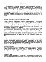
REGULATION
There
is a lot of
legislation concerning ships, much
of it
concerned
with
safety
matters
and the
subject
of
international agreements.
For a
given
ship
the
application
of
this legislation
is the
responsibility
of the
government
of the
country
in
which
the
ship
is
registered.
In the
United
Kingdom
it is the
concern
of the
Department
of
Transport
and
its
executive agency,
the
Marine
Safety
Agency
(MSA).
Authority comes
from
the
Merchant Shipping Acts.
The
MSA
was
formerly
the
Surveyor
General's Organisation.
It is
responsible
for the
implementation
of the
UK
Government's strategy
for
marine
safety
and
prevention
of
pollution
from
ships.
Its
four
primary activities
are
related
to
marine
standards,
surveys
and
certification, inspection
and
enforcement
and
keeping
a
register
of
shipping
and
seamen. Some
of the
survey
and
certification
work
has
been delegated
to
classification societies
and
other recognized
bodies.
Some
of the
matters that
are
regulated
in
this
way are
touched upon
in
other chapters, including subdivision
of
ships, carriage
of
grain
and
dangerous cargoes. Tonnage measurement
has
been discussed above.
The
other
major
area
of
regulation
is the
freeboard demanded
and
this
is
covered
by the
Load
Line
Regulations.
Load lines
An
important insurance against damage
in a
merchant ship
is the
allocation
of a
statutory
freeboard.
The
rules governing this
are
somewhat
complex
but the
intention
is to
provide
a
simple visual check that
a
laden
ship
has
sufficient
reserve
of
buoyancy
for its
intended
service.
The
load line
is
popularly associated with
the
name
of
Samuel
Plimsoll
who
introduced
a
bill
to
Parliament
to
limit
the
draught
to
which
a
ship could
be
loaded. This reflects
the
need
for
some minimum