Intro to Naval Architecture 3E Episode 10 doc
Bạn đang xem bản rút gọn của tài liệu. Xem và tải ngay bản đầy đủ của tài liệu tại đây (1.95 MB, 30 trang )
260
MANOEUVRING
The
spiral manoeuvre
This
is a
manoeuvre aimed
at
giving
a
feel
for a
ship's directional
stability.
From
an
initial straight course
and
steady speed
the
rudder
is
put
over
say 15° to
starboard.
After
a
while
the
ship settles
to a
steady
rate
of
turn
and
this
is
noted.
The
rudder angle
is
then reduced
to 10°
starboard
and the new
steady turn rate noted. This
is
repeated
for
angles
of
5°S,
5°P, 10°P,
15°P,
10°P
and so on. The
resulting steady rates
of
turn
are
plotted against rudder angle.
(a)
Figure
10.4
Spiral
manoeuvre
If
the
ship
is
stable there
will
be a
unique rate
of
turn
for
each
rudder
angle.
If the
ship
is
unstable
the
plot
has two
'arms'
for the
smaller rudder angles, depending upon whether
the
rudder angle
is
approached
from
above
or
below
the
value. Within
the
rudder
angles
for
which
there
is no
unique response
it is
impossible
to
predict
which
way
the
ship
will
turn,
let
alone
the
turn rate,
as
this
will
depend
upon
other disturbing
factors
present
in the
ocean.
The
manoeuvre does
not
give
a
direct measure
of the
degree
of
stability, although
the
range
of
rudder angles over
which
response
is
indeterminate
is a
rough
guide.
To
know
the
minimum
rudder
angle
needed
to
ensure
the
ship
turns
in the
desired direction
is
very
useful.
MANOEUVRING
261
The
pull-out
manoeuvre
This
manoeuvre
1
is
also related
to the
directional
stability
of the
ship.
The
rudder
is put
over
to a
certain angle
and
held
until
the
ship
is
turning
at a
steady rate.
The
rudder
is
returned
to
amidships
and the
change
in the
turn rate
with
time is
noted.
For a
stable ship
the
turn
rate
will
reduce
to
zero
and the
ship takes
up a new
steady straight
line
course.
A
plot
of the log of the
rate
of
turn against time
is a
straight line
after
a
short transition period.
If the
ship
is
unstable
the
turn rate
will
riot
reduce
to
zero
but
there
will
remain some steady rate
of
turn.
The
area under
the
plot
of
turn rate against time gives
the
total heading
change
after
the
rudder angle
is
taken off.
The
smaller this
is the
more
stable
the
ship.
If
the
ship
is
conducting turning trials
it
will
be in a
state
of
steady
turning
at the end of the
run.
If the
rudder
is
centred
the
pull-out
manoeuvre
can be
carried
out
immediately
for
that speed
and
rudder
angle.
MANOEUVRING
DEVICES
Rudder
forces
and torques
Rudder
forces
Rudders
are
streamlined
to
produce high
lift
with
minimum drag. They
are
symmetrical
to
produce
the
same
lift
characteristics whichever
way
they
are
turned.
The
force
on the
rudder,
F,
depends upon
the
cross-
sectional
shape, area
A, the
velocity
Vthrough
the
water
and the
angle
of
attack
a.
The
constant
depends
upon
the
cross
section
and the
rudder
profile,
in
particular
the
ratio
of the
rudder
depth
to its
chord length
and the
degree
of
rounding
off
on the
lower corners.
The
lift
is
also sensitive
to
the
clearance between
the
upper
rudder
surface
and the
hull.
If
this
is
very
small
the
lift
is
augmented
by the
mirror image
of the
rudder
in
the
hull.
f(a)
increases roughly linearly
with
a up to the
stall
angle
which
is
typically
about 35°.
f(a)
will
then decrease.
Various
approximate formulae
have
been proposed
for
calculating
F.
An
early
one
was:
In
this
an
allowance
was
made
for the
effect
of the
propeller
race
by
multiplying
Fby
1.3 for a
rudder immediately behind
a
propeller
and
262
MANOEUVRING
by
1.2 for a
centreline rudder behind
twin
screws.
Other
formulations
based
on the
true speed
of the
ship are:
The
first
two
were
proposed
for
twin
rudders behind
twin
screws
and
the
third
for a
centreline rudder behind
a
single
screw.
If
wind
or
water
tunnel data
is
available
for the
rudder cross section
this
should
be
used
to
calculate
the
lift
and the
centre
of
pressure
position.
Typically
the
rudder area
in
merchant ships
is
between
^
and
^
of the
product
of
length
and
draught.
Rudder
torques
To
establish
the
torque needed
to
turn
a
rudder
it is
necessary
to
find
the
position
on the
rudder
at
which
the
rudder
force
acts. That
position
is the
centre
of
pressure.
For a
rectangular
flat
plate
of
breadth
B
at
angle
of
attack
a,
this
can be
taken
as
(0.195
+
0.305
sin a) B aft of
the
leading edge.
For a
typical
rudder section
it has
been
suggested
2
that
the
centre
of
pressure
for a
rectangular rudder
can be
taken
at
K
X
(chord
length)
aft of the
leading edge, where:
The
open
water
figure
is
used
for
both
configurations
for a
ship going
astern.
For
a
non-rectangular
rudder
an
approximation
to the
centre
of
pressure position
can be
obtained
by
dividing
the
rudder into
a
number
of
rectangular sections
and
integrating
the
individual
forces
and
moments over
the
total area. This method
can
also
be
used
to
estimate
the
vertical location
of the
centre
of
pressure, which dictates
the
bending moment
on the
rudder
stock
or
forces
on the
supporting
pintles.
Example
10.1
A
rudder
with
an
area
of 20
m
2
when turned
to 35° has the
centre
of
pressure
1.2m
from
the
stock centreline.
If the
ship
speed
is 15
knots,
and the
rudder
is
located
aft of the
single propeller,
calculate
the
diameter
of the
stock able
to
take this torque,
assuming
an
allowable stress
of 70
MN/m
2
.
MANOEUVRING
263
Solution
Using
the
simple
formula
from
above
to
calculate
the
rudder
force
and a
factor
of 1.3 to
allow
for the
screw
race:
This
can be
equated
to
qf/r
where
r is the
stock
radius,
q is the
allowable
stress,
and/is
the
second moment
of
area about
a
polar
axis
equal
to
Jtr
4
/^.
Hence
In
practice
it
would
be
necessary
to
take
into account
the
shear
force
and
bending moment
on the
stock
in
checking that
the
strength
was
adequate.
The
bending moment
and
shear
forces
will
depend upon
the
way
the
rudder
is
supported.
If
astern speeds
are
high
enough
the
greatest torque
can
arise then
as the
rudder
is
less
well
balanced
for
movements astern.
Rudder
types
The
rudder
is the
most common
form
of
manoeuvring device
fitted in
ships.
Its
action
in
causing
the
ship
to
turn
has
already
been
discussed.
In
this section
it is
proposed
to
review
briefly
some
of the
more
common
types.
Conventional rudders
These
have
a
streamlined section
to
give
a
good
lift
to
drag ratio
and
are of
double-plate
construction. They
can be
categorized according
to
the
degree
of
balance. That
is how
close
the
centre
of
pressure
is to the
rudder
axis.
A
balanced rudder
will
require less torque
to
turn
it.
They
are
termed
balanced,
semi-balanced
or
unbalanced.
The
other method
of
categorization
is the
arrangement
for
suspending
the
rudder
from
the
264
MANOEUVRING
hull. Some have
a
pintle
at the
bottom
of the
rudder,
others
one at
about
mid
depth
and
others
have
no
lower pintle.
The
last
are
termed
spade
rudders
and it is
this type which
is
most commonly
fitted in
warships.
Different
rudder
types
are
shown
in
Figures 10.5
to
10.7.
The
arrangements
are
self explanatory.
(b)
Figure
10.5 Balanced
rudders
(a)
Simplex;
(b)
Spade
MANOEUVRING
265
Figure
10,6 Unbalanced rudder
Special
rudders
A
number
of
special rudders have been
proposed
and
patented over
the
years.
The aim is
usually
to
improve
the
lift
to
drag ratio achieved.
A.
flap
rudder,
Figure 10.8, uses
a flap at the
trailing edge
to
improve
the
lift
by
changing aerofoil shape.
Typically,
as the
rudder turns,
the flap
goes
to
twice
the
angle
of the
main rudder
but in
some rudders
the
flaps can be
moved independently.
A
variant
is the
Flettner
rudder
which
uses
two
narrow
flaps at the
trailing
edge.
The flaps
move
so as to
assist
the
main rudder movement reducing
the
torque required
of the
steering
gear.
266
MANOEUVRING
Figure
10.7 Semi-balanced rudder
Figure
10.8
Flap
rudder
In
semi-balanced
and
unbalanced rudders
the fixed
structure ahead
of
the
rudder
can be
shaped
to
help augment
the
lateral
force
at the
rudder.
Active
rudders
These
are
usually
spade
type
rudders
but
incorporating
a
faired
housing
with
a
small
electric motor driving
a
small propeller. This
provides
a
'rudder'
force
even
when
the
ship
is at
rest
when
the
hydrodynamic
forces
on the
rudder would
be
zero.
It is
used
in
ships
requiring
good
manoeuvrability
at
very
low
speeds.
MANOEUVRING
267
The
Kitchen
rudder
This
rudder
is a
two-part
tube shrouding
the
propeller
and
turning
about
a
vertical axis.
For
ahead propulsion
the two
halves
of the
tube
are
opened
to
fore
and aft flow. For
turning
the two
halves
can be
moved
together
to
deflect
the
propeller race.
The two
halves
can be
moved
to
block
the
propeller
race
and
reverse
its flow.
Figure
10,9
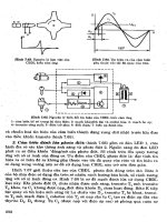
Kitchen
rudder
Vertical
axis
propeller
This
type
of
propeller
is
essentially
a
horizontal disc carrying
a
number
of
aerofoil shaped vertical blades.
As the
disc turns
the
blades
are
caused
to
turn about their vertical axes
so
that they create
a
thrust.
For
normal propulsion
the
blades
are set so
that
the
thrust
is
fore
and
aft.
When
the
ship wishes
to
turn
the
blades
are
adjusted
so
that
the
thrust
is
at an
angle. They
can
produce lateral thrust even
at low
ship
speed.
Lateral
thrust
units
It
is
sometimes desirable
to be
able
to
control
a
ship's head
and
course
independently. This situation
can
arise
in
mine
countermeasure
vessels
which
need
to
follow
a
certain path relative
to the
ground
in
conditions
268
MANOEUVRING
Figure
10.10
Vertical axis
rudder
(a)
Construction
(b)
Operation
MANOEUVRING
269
of
wind
and
tide.
Other
vessels demanding good
positional
control
are
offshore
rigs. This leads
to a
desire
to
have
the
ability
to
produce lateral
thrusts
at the bow as
well
as the
stern.
It has
been seen that
bow
rudders
are
likely
to be
ineffective
because
of
their proximity
to the
neutral
point.
The
alternative
is to put a
thrust unit, usually
a
contra-rotating
propeller,
in a
transverse tube. Such devices
are
called
lateral
thrust
units
or bow
thrust
units
when
fitted
forward.
Their
efficiency
is
seriously
reduced
by a
ship's
forward
speed,
the
thrust being roughly halved
at
about
two
knots. Some
offshore
rigs
have
dynamic
positional control
provided
by a
number
of
computer controlled lateral thrust
units.
SHIP
HANDLING
Several
aspects
of the
handling
of a
ship
are not
brought
out by the
various
manoeuvres discussed above.
Handling
at low
speed
At
low
speed
any
hydrodynamic
forces
on the
hull
and
rudders
are
small
since
they
vary
as the
square
of the
speed.
The
master
must
use
other means
to
manoeuvre
the
ship,
including:
(1)
Using
one
shaft,
in a
twin
shaft
ship,
to go
ahead
while
the
other
goes astern.
(2)
When leaving,
or
arriving
at, the
dockside
a
stern
or
head rope
can
be
used
as a
pivot
while
going ahead
or
astern
on the
propeller,
(3)
Using
the
so-called
paddle
wheel
effect
which
is a
lateral
force
arising
from
the
non-axial
flow
through
the
propeller.
The
force
acts
so as to
cause
the
stern
to
swing
in the
direction
it
would
move
had the
propeller
been
a
wheel running
on a
hard surface.
In
twin
screws
the
effects
generally balance
out
when both
shafts
are
acting
to
provide ahead
or
astern thrust.
In
coming
alongside
a
jetty
a
short burst astern
on one
shaft
can
'kick'
the
stern
in
towards
the
jetty
or
away
from
it
depending
which
shaft
is
used.
(4)
Using
one of the
special devices described above.
For
instance
a
Kitchen
rudder,
a
vertical
axis
propeller
or a
lateral
thruster.
Interaction
between
ships
As
discussed
in
Chapter
8 on
resistance
a
ship creates
a
pressure
field
as
it
moves through
the
water.
The field
shows
a
marked increase
in
pressure
near
the bow and
stern
with
a
suction over
the
central
portion
of the
ship. This pressure
field
acts
for
quite
an
area around
270
MANOEUVRING
the
ship. Anything
entering
and
disturbing
the
pressure
field
will
cause
a
change
in the
forces
on the
ship,
and
suffer
forces
on
itself.
If
one
ship passes close
to
another
in
overtaking
it, the
ships
initially
repel each other. This repulsion
force
reduces
to
zero
as the bow of
the
overtaking ship reaches
the
other's
amidships
and an
attraction
force
builds
up.
This
is at a
maximum soon
after
the
ships
are
abreast
after
which
it
reduces
and
becomes
a
repelling
force
as the two
ships
part company. When running abreast
the
ships experience
bow
outward
moments.
As
they approach
or
break
away
they
suffer
a bow
inward
moment
3
.
Such
forces
are
very
important
for
ships
when
they
are
replenishing
at
sea
4
.
Similar
considerations apply
when
a
ship approaches
a fixed
object.
For
a
vertical
canal bank
or
jetty
the
ship experiences
a
lateral
force
and yaw
moment. Open structure jetties
will
have
much less
effect
than
a
solid one.
In
shallow water
the
reaction
is
with
the sea bed and
the
ship experiences
a
vertical force
and
trimming moment resulting
in
a
bodily sinkage
and
trim
by the
stern. This
can
cause
a
ship
to
ground
in
water
which
is
nominally
several
feet
deeper than
the
draught
5
.
The
sinkage
is
known
as
squat
This phenomenon
has
become more
important
with
the
increasing
size
of
tankers
and
bulk carriers. Squat
is
present even
in
deep
water
due to the
different
pressure
field
around
the
ship
at
speed.
It is
accentuated,
as
well
as
being more
significant,
in
shallow
water.
In a
confined
waterway
a
blockage
effect
occurs once
the
ship's sectional area exceeds
a
certain percentage
of the
waterway's
cross
section. This
is due to the
increased speed
of the
water
which
is
trying
to
move
past
the
ship.
For
narrow channels
a
blockage
factor
mid
a
velocity-return
factor
6
have
been
defined
as:
A
formula
for
estimating squat
at
speed
Vin
open
or
confined
waters
is:
Cg
being
the
block
coefficient.
MANOEUVRING
271
A
simplified
formula
for
open
water
7
is:
Other approximate
approaches
8
are to
take squat
as 10 per
cent
of
the
draught
or as 0.3
metres
for
every
five
knots
of
speed.
DYNAMIC
STABILITY
AND
CONTROL
OF
SUBMARINES
Modern
submarines
can
travel
at
high speed although sometimes their
function
requires them
to
move
very
slowly.
These
two
speed regimes
pose quite
different
situations
as
regards their
dynamic
stability
and
control
in the
vertical
plane.
The
submarine's static stability dominates
the
low
speed performance
but has
negligible influence
at
high
speed.
For
motions
in the
horizontal plane
the
submarine's problems
are
similar
to
those
of a
surface
ship except that
the
submarine, when
deep,
experiences
no
free
surface
effects.
At
periscope
depth
the
free
surface
becomes
important
as it
affects
the
forces
and
moments
the
submarine
experiences,
but
again
mainly
in the
vertical plane.
A
submarine must avoid hitting
the sea bed or
exceeding
its
safe
diving
depth and,
to
remain covert, must
not
break
surface.
It has a
layer
of
water
in
which
to
manoeuvre
which
is
only about
two or
three
ship lengths deep.
At
high speed there
is
little time
to
take corrective
action
should anything
go
wrong.
By
convention submarines
use the
term
pitch angle
for
inclinations about
a
transverse horizontal axis (the
trim
for
surface ships)
and the
term trim
is
used
to
denote
the
state
of
equilibrium
when
submerged.
To
trim
a
submarine
it is
brought
to
neutral
buoyancy
with
the
centres
of
gravity
and
buoyancy
in
line.
The
approach
to the
problem
is
like
that used
for the
directional
stability
of
surface ships
but
bearing
in
mind that:
(1)
The
submarine
is
positively
stable
in
pitch angle.
So if it is
disturbed
in
pitch
while
at
rest
it
will
return
to its
original
trim
angle.
(2)
The
submarine
is
unstable
for
depth changes
due to the
compressibility
of the
hull.
(3)
It is not
possible
to
maintain
a
precise balance between
weight
and
buoyancy
as
fuel
and
stores
are
used
up.
The
last
two
considerations
mean that
the
control surfaces must
be
able
to
provide
a
vertical
force
to
counter
any out of
balance
force
and
moment
in the
vertical
plane.
To
control depth
and
pitch separately
272
MANOEUVRING
Figure
10.11
Submarine
in
vertical plane
requires
two
sets
of
control surface,
the
hydroplanes,
one
forward
and
one
aft.
Consider
a
submarine turning
in the
vertical plane
as in
Figure
10.11.
Taking
the
combined
effects
of the two
sets
of
hydroplanes
as
represented
by a
term
in
6
H
the
equations
of
motion
for the
vertical
plane
are
given
by:
These
are
similar
to the
equations
for the
directional stability
of a
surface
ship.
In
this case
Z and
M
are the
vertical force
and
pitching
moment. Subscripts
w,
q and
#H
denote differentiation
with
respect
to
the
variable concerned.
In
these equations:
mqV'm
a
centrifugal
force
term
mgBQB
is a
statical
stability
term,
BG
being
the
distance between
B
andG.
This
stability term
is
constant
for all
speeds whereas
the
moments
M
vary
with
the
square
of the
velocity.
The
stability term
can
normally
be
ignored
at
speeds
greater than
10
knots. Ignoring this term
for the time
being
and
eliminating
w
between
the two
equations leads
to the
condition that
for the
submarine
to
have positive dynamic
stability:
This
is
termed
the
high
speed
stability criterion.
If
this criterion
is met and
the
submarine
is
statically stable,
it
will
be
stable
at all
speeds.
If the
criterion
is not met
then
a
statically stable submarine
will
develop
a
diverging
oscillation
at
forward
speeds above some critical value.
MANOEUVRING
273
The
equations
can be
manipulated
9
to
derive
a
number
of
interesting
relationships:
(1)
The
steady path
in the
vertical plane cannot
be a
circle unless
BG
is
zero.
(2)
The
rate
of
change
of
depth
is
zero
if
(3)
The
pitch angle
is
zero
if
M$
H
/Z$
H
~
M^/Z^
but the
depth
rate
is
not
zero
but
given
by
<5
H
Z3
H
/^v
(4)
The
ratio
M
W
/Z
W
defines
the
distance
forward
of G of a
point
known
as the
neutral
point.
A
vertical force applied
at
this point
causes
a
depth change
but no
change
in
pitch angle.
(5)
A
second point,
known
as the
critical
point,
is
distant
mgBG/VZ^
aft
of the
neutral point.
A
vertical force
applied
at the
critical
point
will
cause
no
change
of
depth
but
will
change
the
pitch
angle.
A
downward
force
forward
of the
critical point
will
increase depth,
a
downward force
aft of the
critical point
will
reduce depth. Thus
at
this point there
is a
reversal
of the
expected result
of
applying
a
vertical force.
(6)
As
speed drops
the
critical point
moves
aft.
At
some speed,
perhaps
two or
three
knots,
the
critical
point
will
fall
on the
after
hydroplane
position.
The
speed
at
which
this happens
is
termed
the
critical
speed.
Figim
10.12 Neutral
and
critical points
274
MANOEUVRING
MODIFYING
THE
MANOEUVRING
PERFORMANCE
As
with
other aspects
of
ship performance
it is
difficult,
and
sometimes
dangerous,
to
generalize
on the
effect
of
design changes
on a
ship's
manoeuvring
qualities. This
is
because
so
many
factors
interact
and
what
is
true
for one
form
may not be
true
for
another. Broadly however
it
can be
expected that:
(1)
Stern trim improves directional
stability
and
increases turning
diameter.
(2)
A
larger rudder
can
improve directional stability
and
give
better
turning.
(3)
Decrease
in
draught
can
increase turning rate
and
improve
directional stability. This
is
perhaps
due to the
rudder becoming
more dominant relative
to the
immersed hull.
(4)
Higher length
to
beam ratios lead
to a
more stable ship
and
greater
directional stability.
(5)
Quite marked changes
in
metacentric
height, whilst
affecting
the
heel during
a
turn, have little
effect
on
turning rate
or
directional stability.
(6)
For
surface ships
at a
given rudder angle
the
turning circle
increases
in
diameter
with
increasing
speed
but
rate
of
turn
can
increase.
For
submarines turning diameters
are
little
affected
by
speed.
(7)
A
large skeg
aft
will
increase directional
stability
and
turning
circle diameter.
(8)
Cutting
away
the
below
water
profile
forward
can
increase
directional
stability.
By
and
large
the
hull design
of
both
a
surface ship
and a
submarine
is
dictated
by
considerations other than manoeuvring.
If
model tests show
a
need
to
change
the
manoeuvring performance this would normally
be
achieved
by
modifying
the
areas
and
positions
of the
control
surfaces
and
skegs.
SUMMARY
The
reasons
a
ship requires certain levels
of
manoeuvrability have been
discussed
and the
difficulties
in
defining
any
standard
parameters
for
studying
the
matter
pointed
out. Various
standard
manoeuvres
used
in
defining
a
vessel's directional stability
and
turning performance have
been described.
A
number
of
rudder
types
and
other devices
for
manoeuvring
ships have been reviewed.
The
special case
of a
MANOEUVRING
275
submarine moving
in
three
dimensions
has
been touched upon
together
with
the
action
of the
control
forces
in
controlling pitch angle
and
depth.
References
1.
Burcher,
R.
K.
(1991)
The
prediction
of the
manoeuvring characteristics
of
vessels.
The
Dynamics
of
Ships,
The
Royal
Society, London.
2.
Gawn,
R, W.
(1943)
Steering
experiments, Part
1.
TINA,
3.
Newton,
R.
N.
(1960) Some notes
on
interaction
effects
between ships close
aboard
in
deep
water.
First symposium
on
ship manoeuvrability,
David
Taylor
Model
Seisin,
4.
Chislett,
H. W. J.
(1972) Replenishment
at
sea.
TRINA.
5.
Dand,
I. W.
(1981)
On
ship-bank
interaction.
TRINA.
6.
Dand,
I. W. and
Ferguson,
A. M.
(1973)
The
squat
of
full
ships
in
shallow
water.
TRINA.
7.
Barrass,
C. B.
(1978) Ship squat,
Polytech
International
8.
Dand,
I. W.
(1977)
The
physical causes
of
interaction
and its
effects.
Nautical
Institute
Conference
on
Ship
Handling,
9.
Nonweiler,
T. R. F.
(1961)
The
stability
and
control
of
deeply submerged submarines.
TRINA.
11
Vibration,
noise
and
shock
Ships
must
be
designed
so as to
provide
a
suitable environment
for the
continuous,
efficient
and
safe
working
of
equipment
and
crew.
Also
the
environment should
be one in
which crew
and
passengers
will
be
comfortable.
Vibration, noise
and
shock
are all
factors
in
that
environment.
A
ship responds
to any
applied
force.
For
some responses,
for
instance those
of
roll, pitch
and
heave
in a
seaway,
it is
acceptable
to
regard
the
ship
as a rigid
body.
In all
cases however there
will
be
some
flexing
of
the
structure
and the
total response
will
include movements
of
one
part
of the
structure relative
to
others. These
can be
termed
the
elastic
body responses
or
degrees
of
freedom
and
they
can be
very
important.
Even
in
ship motions slamming must
be
treated
as a
dynamic,
vibratory response.
The
vibratory stresses
can
increase
the
overall
hull stresses quite considerably
and
must
be
taken into
account,
particularly
in
fatigue studies. Vibration, noise
and
shock
are all
manifestations
of the
ship's elastic responses.
VIBRATION
In
this chapter general vibrations
of
ships
are
considered.
The
most
common
sources
of
vibration excitation
are
propellers
and
main
machinery.
All
vibration
is
undesirable.
It can be
unpleasant
for
people
on
board
and can be
harmful
to
equipment.
It
must
be
reduced
as
much
as
possible
but it
cannot
be
entirely eliminated.
The
designer
of
systems
and
equipment
to be fitted
must allow
for the
fact
that they
will
have
to
operate
in a
vibratory environment,
fitting
special anti-vibration
mounts,
if
necessary,
for
especially sensitive items.
Vibration
levels
of
machinery
can be
used
to
decide when
a
machine
needs attention
and
often
vibration measuring devices
are fitted as a
form
of
'health
monitoring'.
If
vibration levels start
to
rise
the
cause
can
be
investigated.
A
ship
is a
complex structure
and a
full
study
of its
vibration modes
and
levels
is
very
demanding. Indeed,
in
some cases
it is
necessary
to
276
VIBRATION,
NOISE
AND
SHOCK
27?
resort
to
physical modelling
of
parts
of the
ship
to
confirm results
of
finite
element analyses. However
the
basic
principles
involved
are not
too
difficult
and
these
are
explained.
Simple
vibrations
The
simplest case
of
oscillatory motion
is
where
the
restoring force
acting
on a
body
is
proportional
to its
displacement
from
a
position
of
stable equilibrium. This
is the
case
of a
mass
on a
spring which
is the
fundamental
building block
from
which
the
response
of
complex
structures
can be
arrived
at, by
considering them
as
combinations
of
many
masses
and
springs.
In the
absence
of any
damping
the
body,
once disturbed, would oscillate
indefinitely.
Its
distance
from
the
equilibrium
position
would
vary
sinusoidally
and
such motion
is
said
to
be
simple
harmonic.
This
type
of
motion
was met
earlier
in the
study
of
ship motions
in
still water.
The
presence
of
damping,
due say to
friction
or
viscous
effects,
causes
the
motion
to die
down
with
time.
The
motion
is
also
affected
by
added
mass
effects
due to the
vibrating body
interacting
with
the
fluid
around
it.
These
are not
usually significant
for
a
body vibrating
in air but in
water they
can be
important
There
are
many
standard texts
to
which
the
reader
can
refer
for a
mathematical
treatment
of
these motions.
The
important
findings are
merely
summarized
here.
The
motion
is
characterized
by its
amplitude,
A, and
period,
T.
For
undamped motions
the
displacement
at any time, t, is
given
by:
where:
M
is the
mass
of the
body,
k
is the
force
acting
per
unit displacement,
and
d
is a
phase angle.
The
period
of
this motion
is
T=
2n(M/K)°-
5
,
and
its
freqitency
is
n
=
l/T.
These
are
said
to be the
system's
natural
period
and
frequency.
Damping
All
systems
are
subject
to
some damping,
the
simplest case
being
when
the
damping
is
proportional
to the
velocity.
The
effect
is to
modify
the
period
of the
motion
and
cause
the
amplitude
to
diminish
with
time.
278
VIBRATION,
NOISE
AND
SHOCK
The
period
becomes
T
d
=
&r/
[(A/M)
-
(^/2JW)
2
]°
5
,
frequency
being
l/T
d
,
where/i
is a
damping
coefficient
such that damping
force
equals
ju
(velocity).
Successive
amplitudes
decay
according
to the
equation
As
the
damping increases
the
number
of
oscillations about
the
mean
position
will
reduce until
finally the
body does
not
overshoot
the
equilibrium
position
at
all.
The
system
is
then said
to be
dead
beat.
Regular
forced
vibrations
Free vibrations
can
occur when
for
instance,
a
structural member
is
struck
an
instantaneous blow. More generally
the
disturbing force
will
continue
to be
applied
to the
system
for a
longish
period
and
will
itself
fluctuate
in
amplitude.
The
simplest type
of
disturbing force
to
assume
for
analysis
purposes
is one
with
constant amplitude
varying
sinusoi-
dally
with
time.
This would
be the
case where
the
ship
is in a
regular
wave
system.
The
differential
equation
of
motion, taking
x as the
displacement
at time t,
becomes:
The
solution
of
this equation
for x is the sum of two
parts.
The first
part
is the
solution
of the
equation
with
no
forcing
function.
That
is,
it
is the
solution
of the
damped oscillation previously
considered.
The
second part
is an
oscillation
at the
frequency
of the
applied
force.
It
is
x =
B
sm(a)t
-
y).
After
a time the first
part
will
die
away
leaving
the
oscillation
in the
frequency
of the
forcing
function.
This
is
called
a.
forced
oscillation.
It is
important
to
know
its
amplitude,
B, and the
phase angle,
y.
These
can
be
shown
to be:
In
these expressions
A is
called
the
tuning
factor
and is
equal
to
a)/
(k/M)
0-5
.
That
is the
tuning
factor
is the
ratio
of the frequency of the
applied force
to the
natural
frequency of the
system. Since
k
represents
the
stiffness
of the
system,
F
0
/k
is the
displacement which would
be
caused
by a
static
force
F
0
.
The
ratio
of the
amplitude
of the
dynamic
VIBRATION,
NOISE
AND
SHOCK
279
Figure
11,1
Magnification
factor
displacement
to the
static displacement
is
termed
the
magnification
factor,
Q.
Q
is
given
by:
Curves
of
magnification
factor
can be
plotted against tuning
factor
for
a
range damping
coefficients
as in
Figure
11.1.
At
small values
of A,
Q
tends
to
unity
and at
very
large values
it
tends
to
zero.
In
between these
extremes
the
response
builds
up to a
maximum value which
is
higher
the
lower
the
damping
coefficient.
If the
damping were zero
the
response
would
be
infinite.
For
lighdy
damped
systems
the
maximum
displacement
occurs
very
close
to the
system's
natural
frequency
and
the
tuning
factor
can be
taken
as
unity.
Where
the
frequency
of the
applied
force
is
equal
to the
system's natural
frequency
it is
said that
there
is
resonance.
It is
necessary
to
keep
the
forcing frequency
and
natural
frequency
well
separated
if
large amplitude vibrations
are to be
avoided.
At
resonance
the
expression
for the
phase angle
gives
y
=
tan"
1
oo,
giving
a
phase
lag of
90°.
In
endeavouring
to
avoid resonance
it is
important
to
remember that
many
systems have several natural frequencies associated
with
different
deflection profiles
or
modes
of
vibration.
An
example
is a
vibrating beam
that
has
many modes,
the first
three
of
which
are
shown
in
Figure
11.2.
All
these modes
will
be
excited
and the
overall response
may
show more
than
one
resonance peak.
Figure
11.2
Vibration
modes
280
VIBRATION,
NOISE
AND
SHOCK
Irregular
forcing
function
In
the
above
the
forcing
function
was
assumed sinusoidal
and of
constant
amplitude.
The
more general case would
be a
force
varying
in
an
irregular way.
In
this case
the
force
can be
analysed
to
obtain
its
constituent
regular components
as was
done
for the
waves
in an
irregular
sea.
The
vibratory
response
of the
system
to the
irregular
force
can
then
be
taken
as the sum of its
responses
to all the
regular
components.
SHIP
VIBRATION
The
disturbing forces
A
ship
is an
elastic structure
and
will
vibrate when subject
to
oscillating
forces.
The
forces
may
arise
from
within
the
ship
or be
imposed upon
it
by
external
factors.
Of the
former
type
the
unbalanced forces
in
main
and
auxiliary
machinery
can be
important Rotating machinery such
as
turbines
and
electric motors generally produce forces
which
are of low
magnitude
and
relatively high
frequency.
Reciprocating machinery
on
the
other hand produces larger magnitude forces
of
lower frequency.
Large
main propulsion diesels
are
likely
to
pose
the
most serious
problems
particularly where, probably
for
economic reasons,
4 or 5
cylinder
engines
are
chosen. These
can
have large unbalance
forces
at
frequencies
equal
to the
product
of the
running
speed
and
number
of
cylinders.
These forces
can be at
frequencies
of the
same
order
as
those
of
the
hull vibrations. Thus quite severe vibration
can
occur unless
the
engines
are
very
well
balanced. Auxiliary diesels tend
to run at
higher
speeds. Their frequencies
are
higher
and may
excite local vibrations.
Vibration
forces
transmitted
to the
ship's structure
can be
much
reduced
by flexible
mounting systems.
In
more critical cases vibration
neutralizes
can be fitted in the
form
of
sprung
and
damped weights
which
absorb energy
or
active
systems
can be
used
which
generate
forces
equal
but in
anti-phase
to the
disturbing forces.
Misalignment
of
shafts
and
propeller imbalance
can
cause
forces
at a
frequency
equal
to the
shaft
revolutions.
With
modern production
methods
the
forces
involved should
be
small.
A
propeller
operates
in a
non-uniform
flow and is
subject
to
forces
varying
at
blade rate
frequency,
that
is the
product
of the
shaft
revolutions
and the
number
of
blades. These
are
unlikely
to be of
concern unless there
is
resonance
with
the
shafting
system
or
ship
structure.
Even
in
uniform
flow a
propulsor induces pressure variations
in the
surrounding water
and on
the
ship's hull
in the
vicinity.
The
variations
are
more pronounced
in
non-uniform
flow
particularly
if
cavitation
occurs. Stable
cavitation
over
VIBRATION,
NOISE
AND
SHOCK
281
a
relatively
large
area
is
equivalent
to an
increase
in
blade
thickness
and
the
blade rate pressures increase accordingly.
If
cavitation
is
unstable
pressure
variations
may be
many times greater.
The
number
of
blades
directly
affects
frequency
but has
litde
effect
on
pressure amplitude.
The
probability
of
vibration problems
in
single screw ships
can be
reduced
by
using bulbous
or U
sections rather than
V in the
after
body,
avoiding
near
horizontal buttock lines above
the
propeller,
and by
providing
good
tip
clearance between
propeller
and
hull. Good
tip
clearance
is
important
for all
ships although smaller clearances
are
generally
acceptable
the
greater
the
number
of
blades. Shallow
immersion
of the
propeller
tips should
be
avoided
to
reduce
the
possibility
of air
drawing. Generally
the
wake distribution
in
twin
screw
ships
is
less
likely
to
cause vibration problems.
If
A-brackets
are
used
the
angle between their arms must
not be the
same
as
that between
the
propeller blades
or the
propeller
will
experience enhanced pressure
fluctuations
as the
blades
pass through
the
wake
of the
arms.
A
ship
in
waves
is
subject
to
varying hull pressures
as the
waves
pass.
The
ship's rigid body responses were dealt
with
under seakeeping.
Some
of the
wave
energy
is
transferred
to the
hull
causing main hull
and
local vibrations.
The
main hull vibrations
are
usually classified
as
springing
or
whipping.
The
former
is a
fairly
continuous
and
steady
vibration
in the
fundamental hull mode
due to the
general pressure
field. The
latter
is a
transient caused
by
slamming
or
shipping green
seas. Generally vertical vibrations
are
most important because
the
vertical
components
of
wave
forces
are
dominant. However, horizontal
and
torsional vibrations
can
become large
in
ships
with
large deck
openings
or of
relatively
light scandings such
as
container ships
or
light
aircraft
carriers.
The
additional bending stresses
due to
vibration
may
be
significant
in
fatigue because
of
their
frequency.
The
stresses caused
by
whipping
can be of the
same
order
of
magnitude
as the
wave
bending stresses.
The sMp
responses
Having
considered
the
various disturbing forces
likely
to be
met,
it is
necessary
to
consider
the
ship's oscillatory responses
and
their
frequencies.
Vibrations
are
dealt
with
as
either
local
vibrations
or
main
hull
vibrations.
The
former
are
concerned
with
a
small
part
of the
structure,
perhaps
an
area
of
deck.
The
frequencies
are
usually higher,
and the
amplitudes lower,
than
the
main hull vibrations. Because
there
are so
many
possibilities
and the
calculations
can be
complex they
are not
usually
studied directly during design except where large excitation
forces
are
anticipated. Generally
the
designer avoids machinery
which
282
VIBRATION, NOISE
AND
SHOCK
generate disturbing frequencies close
to
those
of
typical ship type
structures.
Any
faults
are
corrected
as a
result
of
trials
experience.
This
is
often more economic than carrying
out
extensive design calculations
as
the
remedy
is
usually
a
matter
of
adding
a
small amount
of
additional
stiffening.
Main
hull vibrations
are a
different
matter.
If
they
do
occur
the
remedial action
may be
very
expensive. They must therefore
be
looked
at in
design.
The
hull
may
bend
as a
beam
or
twist
like
a rod
about
its
longitudinal axis. These
two
modes
of
vibration
are
called
flexural and
torsional
respectively. Flexing
may
occur
in a
vertical
or
horizontal plane
but the
vertical
flexing is
usually
the
more worrying.
Except
in
lightly structured ships
the
torsional mode
is not
usually
too
important.
Flexuml
vibrations
When
flexing in the
vertical
or
horizontal planes
the
structure
has an
infinite
number
of
degrees
of
freedom
and the
mode
of
vibration
is
described
by the
number
of
nodes
which exist
in the
length.
The
fundamental
mode
is the
two-node
as
shown
in
Figure
11.3.
This yields
a
displacement
at the
ends
of the
ship since there
is no
rigid
support there. This
is
often referred
to as a
free-free
mode
and
differs
from
that which would
be
taken
up by a
structural beam
where
there would
be
zero displacement
at one end at
least.
The
next
two
higher modes have three
and
four nodes.
All are
free-free
and can
occur
in
both planes. Associated
with
each mode
is a
natural
Figure
11,3
(a)
Two-node;
(b)
Three-node;
(c)
Four-node
VIBRATION,
NOISE
AND
SHOCK
283
Table
11.1
Typical
ship
vibration frequencies
Shift
type
Tanker
Passenger
ship
Cargo
ship
Cargo
ship
Destroyer
Length
(m)
227
136
85
130
160
Condition
of
loading
Light
Loaded
Light
Loaded
Light
Loaded
Average
action
2
node
59
52
104
150
135
106
85
85
Frequency
<
Vertical
3 4
:
node
node
nc
121 188
2<
108 166
2$
177
290
283
210
168
180 240
yf
vibration
f
5
2
tde
node
IS
103
10
83
155
230
200
180
135
120
larizontal
3 4
node
nodf.
198 297
159
238
341
353
262
200
frequency
of
free vibration,
the
frequency being higher
for the
higher modes.
If the
ship were
of
uniform
rigidity and
uniform mass
distribution along
its
length
and was
supported
at its
ends,
the
frequencies
of the
higher modes would
be
simple
multiples
of the
fundamental.
In
practice ships
differ
from
this although perhaps
not
as
much
as
might
be
expected,
as is
shown
in
Table
11.1
1
.
It
will
be
noted that
the
greater mass
of a
loaded ship leads
to a
reduction
in
frequency.
Torsional
vibration
In
this case
the
displacement
is
angular
and a
one-node mode
of
vibration
is
possible. Figure
11.4
shows
the first
three modes.
Coupling
It
is
commonly assumed
for
analysis purposes that
the
various modes
of
vibration
are
independent
and can be
treated separately.
In
some
circumstances, however, vibrations
in one
mode
can
generate
vibration
in
another.
In
this case
the
motions
are
said
to be
coupled.
For
instance
in
a
ship
a
horizontal vibration
will
often
excite torsional vibration
because
of the
non-uniform distribution
of
mass
in the
vertical
plane.
284
VIBRATION, NOISE
AND
SHOCK
b
C
Figure
11.4
(a)
One-node;
(b)
Two-node;
(c)
Three-node
Flexing
of
a
beam
Before proceeding to the ship it is instructive to consider the flexural
vibration of a simple beam. Take a beam of negligible mass of length
Z,
supported at its ends and carrying
a
mass Mat its centre. Under static
conditions the deflection at mid span will be
MgZ3/48EL
If the beam is deflected
y
from its ~quilibrium position the restoring
force will be
y(
48EI)
/
13.
Thus
48EI/p
is equivalent to the spring stiffness
k
considered earlier.
It
follows that the frequency of vibration will be:
0.5
-(-)
I
48EI
Om5
=
1.103($)
zn
MP
It can be shown that if the mass
M
is uniformly distributed along the
beam the frequency of vibration becomes:
where
n
is any integer. For
n
=
1,
the frequency
is
1.57(EI/M13)0*5.
The
frequency in which
a
beam vibrates depends upon the method of
support. For vibrations in the free-free mode the frequency becomes:
0.5
where
n
=
4.73,7.85
and
10.99
for the
two-,
three- and four-node modes
respectively.