Plastics Engineered Product Design 1 Episode 8 pptx
Bạn đang xem bản rút gọn của tài liệu. Xem và tải ngay bản đầy đủ của tài liệu tại đây (1.07 MB, 40 trang )
260
Plastics Engineered Product Design
of the pipe industry for steel conduit and pipe
(AWWA
M-11, ASTM,
and
ASME).
Deflection relates
to
pipe stiffness
(El),
pipe radius,
external loads that
will
be imposed on the pipe, both the dead load of
the dirt overburden as well as the live loads such as wheel and rail
traffic, modulus of
soil
reaction, differential soil stress, bedding shape,
and type of backfill.
To
meet the designed deflection of no more than
5%
the pipe wall
structure
could
be
either a straight wall pipe
with
a
thickness of about
1.3 cm
(0.50
in.) or
a
rib wall pipe that provides the same stifhess.
It
has
to
be determined if the wall structure selected is of sufficient
stiffness
to
resist the buckling pressures of burial or superimposed
longitudinal loads. The ASME Standard of a four-to-one safety factor
on critical buckling is used based on many years
of
field experience.
To
calculate the stiffness or wall thickness capable of meeting that design
criterion one must know what anticipated external loads
will
occur (Fig.
4.26).
As
reviewed the strength
of
KTR pipe in its longitudinal and hoop
directions are not equal. Before a final wall structure can be selected,
it
is necessary
to
conduct a combined strain analysis in both the
longitudinal and hoop directions of the RTR pipe. This analysis will
consider longitudinal direction and the hoop direction, material’s
allowable strain, thermal contraction strains, internal pressure, and
pipe’s ability
to
bridge
soft
spots in the trench’s bedding. These values
are determinable through standard ASTM tests such as hydrostatic
testing, parallel plate loading, coupon test, and accelerated aging tests.
Stress-strain
(S-S)
analysis of the materials provides important
information. The tensile
S-S
curve for steel-pipe material identifies its
yield point that is used as the basis in their design. Beyond this static
loaded yield point (Chapter
2)
the steel
will
enter into the range of
plastic deformation that would lead
to
a total collapse of the pipe. The
allowable design strain used is about
two
thirds of the yield point.
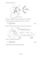
~~~~r~
4.26
Buckling analysis based on conditions such as dead loads, effects
of
possible
flooding, and the vacuum load
it
is expected
to
carry
4
*
Product
design
261
RTR pipe designers also use a
S-S
curve but instead of a yield point,
they use the point of first crack (empirical weep point). Either the
ASTM hydrostatic or coupon test determines it. The weep point is the
point
at
which the RTR matrix (plastic) becomes excessively strained
so
that minute fractures begin
to
appear in the structural wall. At this
point it is probable that in time even a more elastic liner on the inner
wall will be damaged and allow water or other liquid to weep through
the wall. Even with this situation, as is the case with the yield point of
steel pipe, reaching the weep point is not catastrophic.
It
will continue
to withstand additional load before it reaches the point of ultimate
strain and failure. By using a more substantial, stronger liner the weep
point will be extended on the
S-S
curve.
The filament-wound pipe weep point is less than
0.009
in./in. The
design is
at
a strain of
0.0018
in./in. providing
a
5
to
1
safety factor.
For transient design conditions a strain of
0.0030
in./in. is used
providing
a
3
to
1
safety factor.
Stress or strain analysis in the longitudinal and hoop directions is
conducted with strain usually used, since it is easily and accurately
measured using strain gauges, whereas stresses have
to
be calculated.
From
a
practical standpoint both the longitudinal and the hoop analysis
determine the minimum structural wall thickness of the pipe. However,
since the longitudinal strength of RTR pipe
is
less than it is in the hoop
direction, the longitudinal analysis is first conducted that considers the
effects of internal pressure, expected temperature gradients, and ability
of
the pipe to bridge voids in the bedding. Analyzing these factors
requires that several equations be superimposed, one on another.
All
these longitudinal design conditions can be solved simultaneously, the
usual approach is to examine each individually.
Poisson’s ratio (Chapter
3)
can have an influence since a longitudinal
load could exist. The Poisson’s effect must be considered when
designing long or short length of pipe. This effect occurs when an
open-ended cylindcr is subjected to internal pressure.
As
the diameter
of the cylinder expands, it also shortens longitudinally. Since in a buried
pipe movement is resisted by the surrounding soil,
a
tensile
load
is
produced within the pipe. The internal longitudinal pressure load in the
pipe is independent
of
the length of the pipe.
Several equations can be used to calculate the result of Poisson’s effect
on the pipe in the longitudinal direction in terms of stress or strain.
Equation provides
a
solution for
a
straight run of pipe in terms
of
strain. However, where there is
a
change in direction by pipe bends and
thrust blocks
are
eliminated through the use
of
harness-welded joints,
a
262
Plastics Engineered Product Design
different analysis is necessary. Longitudinal load imposed on either side
of an elbow is high. This increased load is the result of internal pressure,
temperature gradient, and/or change in momentum of the fluid.
Because of this increased load, the pipe joint and elbow thickness may
have
to
be increased to avoid overstraining.
The extent
of
the tensile forces imposed on the pipe because of cooling
is
to
be determined. Temperature gradient produces the longitudinal
tensile load. With an open-ended cylinder cooling, it attempts
to
shorten longitudinally. The resistance of the surrounding soil then
imposes a tensile load. Any temperature change in
the
surrounding soil
or medium that the pipe may be carrying
also
can produce
a
tensile
load. Engineering-wise the effects of temperature gradient on a pipe
can be determined in terms of strain.
Longitudinal analysis includes examining bridging if it occurs where the
bedding grade’s elevation or the trench bed’s bearing strength varies,
when
a
pipe projects from
a
headwall, or in
all
subaqueous installations.
Design of the pipe includes making it strong enough
to
support the
weight of its contents, itself, and its overburden while spanning
a
void
of
two
pipe diameters.
When a pipe provides
a
support the normal practice is to solve all
equations simultaneously, then determine the minimum wall thickness
that has strains equal
to
or less than
the
allowable design strain. The
result is obtaining the minimum structural wall thickness. This
approach provides the designer with a minimum wall thickness on
which
to
base the ultimate choice of pipe configuration.
As
an example,
there is
the
situation of the combined longitudinal analysis requiring a
minimum of
5/8
in.
(1.59
cm) wall thickness when the deflection
analysis requires a
1/2
in.
(1.27
cm) wall, and the buckling analysis
requires
a
3/4
in.
(1.9
cm) wall.
As
reviewed the thickness was the
3/4
in.
wall. However with the longitudinal analysis
a
5/8
in. wall is enough to
handle the longitudinal strains likely to
be
encountered.
In deciding which wall thickness, or what pipe configuration (straight
wall or ribbed wall) is
to
be used, economic considerations are involved.
The designer would most likely choose the
3/4
in. straight wall pipe if
the
design analysis was complete, but
it
is
not since there still remains
strain analysis in the hoop direction. Required is to determine if the
combined loads of internal pressure and diametrical bending deflection
will excccd
the
allowable design strain.
There was a tendency in the past to overlook designing of joints. The
performance of the whole piping system is directly related
to
the
performance
of
the
joints rather than just as an internal pressure-seal
pipe. Examples of joints are bell-and-spigot joints with an elastomeric
seal or weld overlay joints designed with the required stiffness and
longitudinal strength. The bell
type
permits rapid assembly of
a
piping
system offering an installation cost advantage.
It
should be able to
rotate at least
two
degrees without
a
loss of flexibility. The weld type is
used
to
eliminate the need for costly thrust blocks.
__1 1.1
Spring
."_
_I-
WJ
-
There is
a
difference when comparing the plastic
to
metal spring shape
designs. With metals shape options
are
the usual torsion bar, helical
coil, and flat-shaped leaf spring. The TPs and TSs can be fabricated into
a
variety of shapes
to
meet different product requirements.
An
example
is TP spring actions with
a
dual action shape (Fig.
4.27)
that is injection
molded. This stapler illustrates a spring design with the body and
curved spring section molded in a single part. When the stapler is
depressed, the outer curved shape is in tension and the ribbed center
section is put into compression. When the pressure is released, the
tension and compression forces are in turn released and
the
stapler
returns
to
its original position.
Other thermoplastics are used
to
fabricate springs. Acetal plastic has
been used as
a
direct replacement for conventional metal springs as well
providing the capability
to
use different spring designs such as in zigzag
springs, un-coil springs, cord locks with molded-in springs, snap fits,
etc.
A
special application is where TP replaced
a
metal pump in a
PVC
plastic bag containing blood. The plastic spring hand-operating pump
(as well as other plastic spring designs)
did
not contaminate the blood.
RP
leaf springs have the potential in the replacements for steel springs.
These unidirectional fiber
Ws
have been used in trucks and automotive
suspension applications. Their use in aircraft landing systems dates back
to the early
1940s
taking advantage of weight savings and
cigurib
:%.27
TP
Delrin acetal plastic molded stapler (Courtesy
of
DuPont)
SPRING
SECTION
264
Plastics Engineered Product Design
performances. Because of the material’s high specific strain energy
storage capability as compared
to
steel, a direct replacement of multileaf
steel springs by monoleaf composite springs can be justified on a
weight-saving basis.
The design advantages of these springs is
to
fabricate spring leaves
having continuously variable widths and thicknesses along their length.
These leaf springs serve multiple functions, thereby providing a
consolidation of parts and simplification of suspension systems. One
distinction between steel and plastic is that complete knowledge of
shear stresses is not important in a steel part undergoing flexure,
whereas
with
RP
design shear stresses, rather than normal stress
components, usually control the design.
Design of spring has been documented in various
SAE
and MTM-STP
design manuals. They provide the equations for evaluating design
parameters that are derived from geometric and material considerations.
However, none of this currently available literature
is
directly relevant
to
the problem of design and design evaluation rcgarding
RP
structures. The design of any
RP
product is unique because the stress
conditions within a given structure depend on its manufacturing
methods, not just its shape. Programs have therefore been developed
on the basis of the strain balance within the spring
to
enable suitable
design criteria
to
be met. Stress levels were then calculated, after which
the design and manufacture of
RP
springs became feasible.
Leaf
Spring
RP/composite leaf springs constructed of unidirectional glass fibers in a
matrix, such as epoxy resin, have been recognized as a viable replace-
ment for steel springs in truck and automotive suspension applications.
Because
of
the material’s high specific strain energy storage capability
compared with steel, direct replacement of multi-leaf steel springs by
mono-leaf composite springs is justifiable on a weight saving basis.
Other advantages
of
RP
springs accrue fiom the ability to design and
fabricate
a
spring leaf having continuously variable width and/or
thickness along its length. Such design features can lead to new suspension
arrangements
in
which the composite leaf spring
will
serve multiple
functions thereby providing part consolidation
and
simplification of the
suspension system.
The spring configuration and material of construction should be
selected
so
as to maximize the strain energy storage capacity per unit
mass without exceeding stress levels consistent with reliable, long life
operation. Elastic strain energy must be computed relative
to
a
4
-
Product design
265
particular stress state. For simplicity,
two
materials are compared, steel
and unidirectional glass fibers in
an
epoxy matrix having
a
volume
fraction of
0.5
for the stress state of uniaxial tension. If
a
long bar of
either material is loaded axially the strain energy stored per unit volume
of material is given by
U=(l&*/2€)
(in-lb/in3)
(4-36)
where
6,
is the allowable tensile stress and
E
is Young’s modulus for the
material.
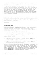
In Table
4.9
the appropriate
E
for each material has been used and a
conservative value selected for
6,.
On a volume basis the
RP
is about
twice as efficient as steel in storing energy; on a weight basis it is about
eight times as efficient.
‘?hi+-
~i-9
Glass
fiber-epoxy
RP
leaf
spring design
Material
oA
(ksi)
U(I
b/in2)
U/w*
(in)
Steel
G
lass/e
poxy
90
60
135
470
325
4880
w
=
specific weight
The
RP
has an advantage because
it
is an anisotropic material
that
is
correctly designed for
this
application whereas steel is isotropic. Under
a different loading condition (such as torsion) the results would be
reversed unless the
RP
were redesigned for that condition. The above
results are applicable to the leaf spring being reviewed because the
principal stress component in the spring will be a normal stress along
the length of the spring that is the natural direction for fiber
orientation.
In
addition
to
the influence of material type
on
elastic energy storage, it
is
also
important
to
consider spring configuration. The most efficient
configuration (although not very practical as a spring) is the uniform
bar in uniaxial tension because the stresses are completely homogeneous.
If the elastic energy storage efficiency is defined as the energy stored per
unit volume, then
the
tensile bar has an efficicncy of
100%.
On that
basis a helical spring made of uniform round wire would have an
efficiency of
32%
(the highest of any practical spring configuration)
while
a
leaf
spring
of uniform rectangular cross section would be only
11%
efficient.
The low efficiency of this latter configuration is due
to
stress gradients
through the thickness (zero at the mid-surface and maximum
at
the
266
Plastics Engineered Product Design
upper and lower surfaces) as well as along the length (maximum at
mid-
span and zero at the tips). Recognition of
this
latter contribution
to
inefficiency led
to
development of so-called constant strength beams
which for a cantilever of constant thickness dictates a geometry of
uiangular plan-form. Such a spring would have an energy storage
efficiency of
33%.
A
practical embodiment of this principle is the multi-
leaf spring of constant thickness, but decreasing length plates, which for
a
typical five leaf configuration would have an efficiency of about
22%.
More sophisticated steel springs involving variable leaf thickness bring
improvements of energy storage efficiency, but are expensive since the
leaves must be forged rather than cut &om constant thickness plate.
However,
a
spring leaf molded of the
RP
can have
both
thickness and
width variations along its length. For instance, a practical
RP
spring
configuration having a constant cross-sectional area and appropriately
changing thickness and width will have an energy storage efficiency of
22%.
This approaches the efficiency of a tapered multi-leaf configuration
and
is accomplished with
a
material whose inherent energy storage
efficiency is eight times better than steel.
In this design, the dimensions of the spring are chosen in such
a
way
that the maximum bending
stresses
(due
to
vertical loads) are uniform
along the central portion
of
the spring. This method of selection of the
spring dimensions allows the unidirectional long fiber reinforced plastic
material
to
be used most effectively. Consequently, the amount of
material needed for the construction of the spring is reduced and the
maximum bending stresses are evenly distributed along the length of
the spring. Thus, the maximum design stress in the spring can be
reduced without paying a penalty for an increase in the weight of the
spring. Two design equations are given in the following using the
concepts described above.
To
develop design formulas for
RP
springs,
we
model a spring as a
Figure
4-28
RP
spring
model
4
-
Product
design
267
-
circular arc or as a parabolic arc carrying a concentrated load
2FV
at
mid-length (Fig.
4.28).
The governing equation for bending of the spring
11M
p
R
E/
=-
(4-37)
where
R
=
radius of curvature of unloaded spring;
p
=
radius of
curvature of deformed spring;
M
=
bending moment,
E
=
Young’s
modulus; and
I
=
moment of inertia of spring cross section.
Using the coordinate system shown in Fig,
4.28,
equation
4-37
is
rewritten as
where the coordinate
y
is
used
to
denote the deformed configuration of
the spring. Once the maximum allowable design stress in the spring is
chosen, equation
4-38
will be used
to
determine the load carrying
capability of the spring. Due to the symmetry of the spring
at
x
=
0,
only half of the spring needs
to
be analyzed.
It
should be noted that
equation
4-38
is
only
an approximate representation of the deformation
of the spring. However, for small values of
A/Z,
it
is
expected
to
give
reasonably good prediction of the spring rate. Here
il
is the arc height
and
2i/Z
is the chord length of the spring. Although a nonlinear relation
can
be
used in place of equation
4-38,
it
would be difficult
to
derive
simple equations for design purposes.
For this particular design, the thicknesses
of
the spring decreases front
the center
to
the
two
ends of the spring. Hence, the cross-sectional area
of the spring varies along its length. The maximum bending stresses at
every cross section of
the
spring from
x
=
0
to
x
=
a,
are assumed
to
be
identical (Fig.
4.28).
The value of
a,
is a design parameter that is used
to
control the thickness and the load carrying capability of the spring. If
a,
is the maximum allowable design stress, then the thickness
of
the
spring for
0
&
I
a,
is determined by equating the maximum bending
stress in the spring
to
a,,
thus:
(4-39)
where
v
is Poisson’s ratio, and
b
and
h
are the width and thickness of
the spring, respectively.
The factor
(I
-
v2)
is introduced
to
account for the fact that
b
could be
several times larger than
h.
If
b
and
h
are of the same order of
magnitude, a zero value of
v
is
suggested
to
be used with equation
4-
268
Plastics Engineered Product Design
39.
This equation shows that the thickness of the spring should be a
function of
Fv
a,,
1,
and
b.
Once
F,,,
a,,
and
I
are fixed, then the value of
h
is inversely proportional to the square root of the width of the spring.
For
x
>a,,
the thickness of the spring is assumed
to
remain constant.
The minimum value of
h
is governed by the ability of the unidirectional
composite
to
carry shear stresses. Using equation
4-38
and the
appropriate boundary and continuity conditions, the following
equation for the determination
of
the spring rate is obtained,
(4-40)
where
L,
is the spring rate per unit width of the spring in lb per in. of
vertical deflection. In deriving equation
4-40,
the maximum bending
stress
a,
is assumed to develop when
y
=
0
at
which the center of the
spring rate has undergone a deflection equal
to
h.
If the actual design
value of
2F,,
is less than or greater than
bkb,
the appropriate value of
a,
to be used in equation
4-74
can be determined easily from the
maximum design stress by treating
a.
as a linear function of
2Fv
A
constraint on the current fabricating method of the
RP
leaf spring is
that
the cross-sectional area of the spring has
to
remain constant along
the length
of
the spring. This imposes
a
restriction on the use of
variable cross-sectional area design since additional work is required to
trim a constant cross-sectional area spring
to
fit
a
variable cross-
sectional area design. Unless the design stresses in the spring are
excessively high, it is preferable
to
use the less labor-intensive constant
cross-sectional area spring. This section describes the design formulae
for this type
of
spring design.
Using the same coordinate system and symbols as shown in Fig.
4.28,
equations
4-37
and
4-38
remain valid for the constant cross-sectional
area spring. The mid-section thickness of the spring
h,,
is related
to
the
maximum bending stress
a,
by:
6(1
-
v2)FvI
h;
=
bo
00
(4-41)
where
bo
is the corresponding mid-section width
of
the spring.
Imposing the constant cross-sectional area constraint,
6oho
=
bh
(4-42)
the thickness
of
the spring at any other section is given by:
(4-43)
The corresponding width of the spring is then obtained
from
equation
4-42.
Based on equations
4-42
and
4-43
that the width of the spring
will continue to increase as
it
moves away from the mid-section. In
general there is
a
limitation on the maximum allowable spring width.
Using
b,,
to
denote the maximum width, the value of
x
beyond which
tapering
of
the spring is not allowed can be determined by imposing
the constant cross-sectional area constraint. One can use
a,,
to
denote
this
value of
x,
then:
a.
=
I
[I-?]
(4-44)
Thus, equation
4-43
holds only for
x
1.
Beyond
x
=
a,
the thickness
of
the spring remains constant and is given by:
6(1
-
V)F
(I
h=
"
X2%
boho~o
(4-45)
An
implication of equations
4-43
and
4-44
is that the maximum
bending stresses will remain constant along the length of the spring for
[XI
>a,.
Equation
4-38
with the appropriate boundary and continuity
conditions, the spring rate,
k,
can be shown
to
be:
3
El0
RA41
-
vz)[l
+
2(1
-
b,lb,)l
k=
(4-46)
where
I,
is the moment
of
inertia of the cross-section of the spring at
mid-section. In the design of
a
spring, the values of
ba,,
1,
R,
h,
and
k
are usually given and it is required to determine the values
of
h,,
for
a
desirable value of
a,.
The following equation has been obtained for the
determination of
h,:
(4-47)
Once
ho
is
determincd, the corresponding value of
bo
is then obtained
from equation
4-37.
In equation
4-47,
the value of
o,,
corresponds to a
center deflection equal to
A.
If the actual design value of
2Fv,
is less
than or greater than
kA,
the appropriate value of
a,
to
be used in
equation
4-47
can be determined easily from the maximum design
stress by treating
a,
as
a
linear function
of
2Fv
Consider, as an example,
the
design of
a
pair of longitudinal rear leaf
springs for a light truck suspension. The geometry of the middle
surface
of
the springs is given as:
I
=
23in
A
=
6in
R
=
44.08 in
b,
=
4.5 in
270
Plastics Engineered Product Design
The design load per spring is
2200
Ib and a spring rate of
367
Ib/in. is
required.
If
oo
is set equal to
53
hi
in
equation
4-47,
two
possible design
values of
bo
are obtained. Using equation
4-41,
the corresponding values
of
bo
are determined. Thus, there are
two
possible constant cross-sectional
area designs for
this
particular spring:
(S)
bo
=
1.074
in,
bo
=
2.484
in.
and
(SS)
bo
=
1.190
in.,
bo
=
2.023
in.
A
value of Young’s modulus of
5.5
x
lo6
psi is used in the design of these springs. This corresponds
to
the
modulus of a unidirectional
RP
with
50~01%
of
glass
fibers. If a value of
a,
less than
53
hi is used in the design, negative and complex values of
bo
are obtained &om equation
4-47.
This indicates that it is impossible
to
design a constant cross-sectional
area spring to
fit
the given design parameters with
a
maximum bending
stress of less than 53 ksi. If a constant width design is required, it can be
shown from equation
4-40
that a spring with a constant width of
2.484
in. and
a
maximum thickness of
1.074
in.
wdl
satisfl all the design
specifications. The corresponding value of
a.
is
18
in. If a constant
width of greater than
2.484
in. is allowed, then a maximum design
stress of less than 53-ksi can be obtained.
The above example shows that
two
plausible constant cross-sectional
area designs are obtained
to
satisfl all the design requirements. If the
spring were subjected only
to
vertical loading, the second design would
be selected since it involves less material. However, if the spring is
expected
to
expericnce other loadings in addition to the vertical load,
then it is necessary
to
investigate the response of the spring
to
these
loadings before
a
decision can be made.
‘l‘he effects
of
these loadings can be determined easily using Castighano’s
Theorem, together with numerical integration. For illustration, a com-
parison summation of the responses of the
two
constant cross-sectional
area spring designs are reviewed:
1.
Rotation
due
to
axle
torque,
MT
:
The rate of rotation of the center
portion
of
the spring due
to
the
axle torque,
MT,
is: design
(S)
=
1.901
x
I
O5
in-lb/radians and design
(SS)
=
1.895
x
lo5
in-lb/
radians.
If
an
axle torque of
15,000
in-lb is used for
MT,
the rotation and
the maximum bending stresses for these
two
springs are
in
table
form:
Rotation, degree Maximum stress
design
(li)
4.5 15.7
design
4.5 15.7
4
-
Product
design
271
The responses of these
two
designs
to
the
axle
torque are,
for
all
practical purposes, identical.
As
in the case of transverse loading,
the maximum bending stresses are uniform along the springs for
[
x]
I
a,.
2.
Effect
of
longitudinal
force,
FL:
The longitudinal force
FL,
will
produce a longitudinal and vertical displacement of the spring.
Using
LL
and
Lv,
to denote the corresponding spring rate associated
with
FL,
results in:
kL
kV
design
(5)
2663
Iblin.
1033
Iblin.
design
(ssl
2516
Iblin.
1008
Iblin.
Assuming that a maximum value of
FL
equal to the design load is
expected
to
be carried by the spring, the deflection and
the
maximum stress experienced by the spring are:
Longitudinal Vertical
Maximum
disp., in.
disp., in. stress,
ksi
design
(5)
0.83 2.13 13.8
design
(SS)
0.87 2.18 13.8
The responses of the
two
designs to the longitudinal force are
essentially identical, The maximum bending stresses are uniform
along the springs for
[
x]
I
cc,.
3.
Effect of
twisting
torque,
ML:
In the usual suspension applications,
leaf springs may be subjected
to
twisting, for example, by an
obstacle under one wheel of
an
axle. For the
two
springs studied
here, the rate
of
twist is: design
(S)
=
1.47
x
IO4
in-lb/radians and
design
(SS)
=
1.23
x
lo4
in-lb/radians.
In addition, due to the geometry of the spring, the twisting torque
ML
will cause the spring to deflect in the transverse direction. The
rate of transverse deflection is: design
(S)
=
3319
in-lb/in.and
design
(SS)
=
2676
in-lb/in.
If a maximum total angle of twist
of
10
degrees is allowed, the
response
of
the spring
will
be:
Twisting torque Lateral deflection Maximum shear
in-lb
in.
stress, ksi
design
(5)
2559
0.77
2.55
design
(55)
2150 0.80 2.58
In calculating the effect of the
twisting
torque, thc transverse shear
modulus of the unidirectional
RP
has been used. For an
RP
with
272
Plastics Engineered Product Design
50~01% of glass fibers, the modulus has
a
value of
4.6
x
lo5-psi. The
maximum shearing stress occurs at
[XI
=
a,.
For dcsigns
(S)
and
(s),
the values
of
a,
are
10.3
in. and 12.66 in., respectively. The
values
of
the bending stresses associated with the twisting torque are
negligibly small.
4.
Effect of tramverse force,
FT:
As
in the case of the twisting torque,
the transverse force,
FT,
will cause the spring
to
twist as well as
to
deflect transversely. The spring rates associated with the transverse
force are:
Twist (in-lblradian] Deflection (Iblin)
design
(5)
3319 600
design
Iss)
2676
458
Assuming that
a
maximum value of
FT
is equal
to
0.5
times the
design load expected
to
be carried by the spring, the deflection and
the maximum stress experienced by the spring will be:
Angle
of
Transverse Max. bending
Max. shear
twist (degree)
deflection (in.) stress (ksi)
stress (ksi)
design
(5)
19 1.83
11.5 6.05
design
(SI
23.6
2.40
15.6 7.38
The angle
of
twist and the maximum shear stresses associated with
this lateral force are rather high. In practice, the spring will have
to
be
properly constrained
to
reduce the angle of twist and the
maximum shear stress
to
lower values. Assuming
that
a
maximum
angle of twist
of
no more than
10
degrees is allowed, the deflection
and the maximum stresses experienced by the spring are:
Angle
of
Transverse Max. bending Max. shear
twist (degree)
deflection (in.) stress (ksi)
stress (ksi)
design
10
1.14
11.5
3.93
design
(ssl
10 1.31 15.6 4.09
The maximum bending stresses occur at the center of the spring
while the maximum shear stresses occur at the ends
of
the spring.
Based
on
the above numerical simulations, it appears
that
both
designs respond approximately the same to all different
types
of
loadings. However, design
(S)
will be preferred since it provides
a
better response
to
the lateral and twisting movement
of
the vehicle.
The maximum bending stress
that
will be experienced by the spring is
obtained
by
assuming a simultaneous application of the vertical and the
longitudinal forces together with the axle torque.
A
maximum bending
stress
of
82.5
ksi is obtained. This bending stress is uniform along the
spring for
[x]
I
q,.
In view of
the
infrequent occurrence of this
maximum bending stress, it is expect that the service life
of
the spring is
guaranteed
to
be long in service. However,
a
maximum shearing stress
close
to
6.3
ksi can
be
reached when the spring is subjected
to
both
twisting torque and transverse force at the same time.
The
value of this
shearing stress may be
too
high for long life application. However,
a
more complete assessment
of
the suitability
of
the design can
only
be
obtained through interaction with the vehicle chassis designers.
Special Spring
As
RP
leaf springs find more applications, innovations in design and
fabrication will follow.
As
an example, certain processes are limited
to
producing springs having the same cross-sectional area from end
to
end.
This
leads to
an
efficient utilization
of
material
in
the energy storage
sense. However, satisfying
the
requirement that the spring become
increasingly thinner towards
the
tips can present
a
difficulty in
that
the
spring width
at
the tip may exceed space limitations in some
applications. In that case, it
will
be necessary
to
cut the spring
to
an
allowable width after fabrication. There arc special processes such
as
basic filament winding that can fabricate these type structures.
A
similar post-molding machining operation is required
to
produce
variable thickness/constant width springs. In both instances end
to
end
continuity of the fibers is lost by trimming
the
width. This is of
particular significance near the upper and lower faces of
the
spring that
are subject
to
the highest
levels
of tensile and compressive normal
stresses.
A
practical compromise solution is illustrated in Fig.
4.29.
Here
excess material is forced out
of
a
mid-thickness region during molding
that maintains continuity
of
fibers in the highly
stressed
upper and
Spring
with
a
practical loading solution
5
I_./pI
*
0
,>c;
274
Plastics Engineered Product Design
Figure
4.30
Spring has a bonded bracket
lower face regions.
A
further advantage is that
a
natural cutoff edge is
produced. The design of such a feature into the mold must be done
carefully
so
that the molding pressure (desirable for void-free parts) can
be maintained.
An
area of importance is that of attaching the spring
to
the vehicle.
Since the
RP
spring is a highly anisotropic part especially designed
as
a
flexural element, attachments involving holes or poorly distributed
clamping loads may be detrimental. For example, central clamping of
the spring with
U
bolts
to
an axle saddle
will
produce local strains
transverse
to
the fibers that in combination with transverse strains due
to
normal bending may result in local failure in the plastic matrix. The
use of a hole for a locating bolt in the highly stressed central clamped
region should
also
be avoided.
Load
transfer
from
the tips of the
RP
spring
to
the vehicle is particularly
difficult if it is via transverse bushings
to
a
hanger bracket or shackles
since the bushing axis is perpendicular
to
all
the reinforced fibers. One
favorable design
is
shown in Fig.
4.30.
This
design utilizes a molded
random fiber
RP
(SMC;
Chapter
1)
bracket that is bonded
to
the
spring. Load transfer into this part from the spring occurs gradually
along the bonded region and results in shear stresses that are
conservative for the adhesive as well as both composite parts.
Can
ti
lever Spring
The
cantilever spring (unreinforced or reinforced plastics) can be
employed
to
provide a simple format fkom a design standpoint.
Cantilever springs, which absorb energy by bending, may be treated as
a
series of beams. Their deflections and stresses
are
calculated as short-
term individual beam-bending stresses under load.
The
calculations arrived at for multiple-cantilever springs
(two
or more
beams joined in a zigzag configuration, as in Fig.
4.31)
are similar to,
4
-
Product
design
275
__I___
-
P
c!gurn
43
2
Multiple-cantilever zigzag beam
spring (Courtesy
of
Plastics
FALLO)
but may not be as accurate as those for
a
single-beam spring. The top
beam is loaded
(F)
either along its entire length or
at
a
fixed point. This
load gives
rise
to
deflection
y
at
its
fiee
end and moment
M
at
the fixed
end. The second beam load develops a moment
M
(upward)
and
load
F
(the
effective portion of load
F,
as determined by
the
various angles) at
its
free
end. This moment results
in
deflection
y2
at
the
free
end and
moment
M2
at
the
fixed end (that is,
the
free end
of
the next beam).
The third beam is loaded by
Mz
(downward) and force
F2
(the
effective
portion of
Fl).
This
type
action continues.
Total deflection,
y,
becomes
the
sum of the deflections of the individual
beams. The bending stress, deflection, and moment
at
each point can
be
calculated by using standard engineering equations.
To
reduce stress
concentration,
all
corners should be fully radiused. The relative lengths,
angles, and cross-sectional areas can
be
varied
to
give the desired spring
rate
F/y
in the available space. Thus, the
total
energy stored in
a
cantilever spring is equal to:
fc
=
'12
Fy
(4-48)
where
F
=
total load
in
Ib,
y
=
deflection in., and
E,
=
energy
absorbed by the cantilever spring, in-lbs.
Torsional
Beam
Spring
Torsional beam spring design absorbs
the
load energy by its twisting
action through an angle zero. Fig.
4.32
is an example of its behavior is
that
of
a
shaft in torsion
so
that
it is considered
to
have failed
when
the
strength of the material in shear is exceeded.
For
a
torsional load the shear strength used in design should be
the
value obtained from the industry literature (material suppliers,
etc.)
or
one half the ultimate tensile strength, whichever
is
less. Maximum shear
276
Plastics Engineered Product Design
Figure
4.32
Example
of
a
shaft
under torque
stress on a shaft in torsion is given by the following equation using the
designations from Fig.
4.32:
z
=
TJJ
(4-49)
where
T=
applied torque in in-lb,
c=
the distance from the center
of the shaft to the location on the outer surface of shaft where the
maximum shear stress occurs, in. and
J
=
the polar
moment of inertia, in.4.
Using mechanical engineering handbook information the angular
rotation
of
the shaft is caused by torque
that
is developed by:
e
=
TUGJ
(4-50)
where
L
=
length of shaft, in.,
G=
shear modulus, psi
=
€/2
(1
+
v),
E-
tensile modulus of elasticity, psi, and
v
=
Poisson’s ratio.
The energy absorbed by a torsional spring deflected through angle
0
equals:
E*
=
’I2
M,
x
8
(4-51)
where M,=the torque required for deflection Bat the free end of the
spring, in-lb.
Hinge
____.
-
Since many different plastics are flexible (Chapter
1)
they are used
to
manufacture hinges. They can operate in different environ-
ments. Based on the plastic used they can meet
a
variety of load
performance requirements. Land length
to
thickness ratio is usually
at
least
3
to
1.
Hinges can be fabricated by using different processes such as injection
molding, blow molding, compression molding, and cold worked.
So
called “living hinges” use the
TP’s
molecular orientation to provide
the
bending action in the plastic hinge. With proper mold design (proper
melt flow direction, eliminate weld line, etc.) and process control
fabricating procedures these integral hinge moldings operate efficiently.
4
-
Product
design
277
~~.IILII
x
Otherwise problems in service immediately or shortly after initial use
delamination occurs. Immediate post-mold flexing while it is still hot is
usually required
to
ensure its proper operation.
Hinges depend not only on processing technique but using the proper
dimensions based on the type plastic used. Dimensions can differ if the
hinge is
to
move
45"
to
180".
If the web land length is too short for the
180"
it will self-destruct due
to
excessive loads
on
the plastic's land.
Press
fit
~lll_llll
Press fits that depend
on
having
a
mechanical interface provide a fast,
clean, economical assembly. Common usage is
to
have a plastic hub or
boss that accepts either a plastic or metal shaft or pin. Press-fit
procedure tends
to
expand the hub, creating tensile or hoop stress. If
the interference is
too
great, a high strain and stress will develop. Thus
it
may fail immediately, by developing
a
crack parallel
to
the
axis
of
the
hub
to
relieve the stress, which is
a
typical hoop-stress failure. It could
survive the assembly process, but fail prematurely in use for a variety of
reasons related
to
its high induced-stress levels. Or
it
might undergo
stress relaxation sufficient
to
reduce the stress
to
a lower level that can
be maintained (Chapter
2).
Hoop-stress equations for press-fit situations
are
used. Allowable design
stress or strain will depend upon the particular plastic, the temperature,
and other environmental considerations. Hoop stress can be obtained
by multiplying the appropriate modulus. For high strains,
the
secant
modulus
will
give the initial stress; the apparent or creep modulus
should be used for longer-term stresses. The maximum strain
or
stress
must be below the value that will produce creep rupture in the material.
There could be a weld line in the hub that can significantly affect the
creep-rupture strength of most plastics.
Complications could develop during processing with press fits in that a
round hub or boss may not be the correct shape. Strict processing
controls are used
to
eliminate these type potential problems. There is a
tendency for
a
round hub
to
be slightly elliptical in cross-section,
increasing the stresses
on
the part. For critical product performance and
in view of what could occur, life-type prototyping testing should be
conducted under actual service conditions in critical applications.
The consequences of stress occurring will depend upon many factors,
such as temperature during and after assembly
of
the press
fit,
modulus
of the mating material, type
of
stress, usage environment and probably
278
Plastics
Engineered Product Design
the most important is the type of material being used. Some substances
will creep or
stress
relaxes, but others
wilI
fracture or craze if the strain
is
too
high. Except for light press fits,
this
type
of
assembly design can
be risky enough for the novice, because
a
weld line might already
weaken
the
boss.
Associated with press
fit
assembly methods are
others
such as molded-in
inserts usually used
to
develop good holding power between the insert
and
the
molded plastic.
Snap
fit
l__l
__I
-
Snap fits are used in all kinds of products ranging fi-om toys
to
highly
loaded mechanical tools. There are both temporary and permanent
assemblies, principally in injection and blow molded products. The
following guidelines are recommended regarding the position of the
snap joint
to
the
injection molded gate
and
thc choice
of
the wall
thicknesses
in
the area of flow
to
the place
of
joining:
(1)
there should
be no binding seams at critical points;
(2)
avoid binding seams created
by stagnation
of
the melt during filling;
(3)
the plastic molecules and
the filler should be oriented in the direction
of
stress; and
(4)
any
uneven distribution
of
the filler should not occur
at
high-stress points.
Use
of snap
fits
provides an economical approach where structural and
nonstructural members can be molded simultaneously with the finished
product and provide rapid assembly when compared with such other
joining processes as screws.
As
in other product design approaches
(nothing is perfect), snap fits have limitations such as those described in
Table
4.10.
Snap fits can be rectangular or of a geometrically more complex cross-
section. The design approach for the snap
fit
beam is that either its
thickness or width tapers from the root
to
the hook. Thus, the load-
bearing cross-section at any location relates more
to
the local
load.
Result is that the maximum strain
on
the plastic can
be
reduced and less
material will be used. With this design approach, the vulnerable cross-
section is always
at
the root.
Geometry for snap joints should be chosen in such
a
manner that
excessive increases in stress do not occur. The arrangement of the
undercut should be chosen in such
a
manner that deformations of the
molded product from shrinkage, distortion, unilateral heating, and
loading do not disturb its functioning
Snap fits can be applied
to
any combination of materials, such as plastic
?Pi
'
",
:*
Snap
fit
behaviors
Advantages
Compact, space-saving form
Takes
over other functions like bearing, spring cushioning, fixing
Higher forces can also be transmitted with proper designing
Small number of individual parts
Assembly of a construction system with little expenditure
of
production facilities and time
Can be easily integrated into the structural member
Disadvantages
Influence of environmental effects (such as distortion due to temperature differences)
on
the functioning
Effects of processing
on
the properties of the
snap
joints
(orientation of the molecules
and of the filler, distribution of the filler, binding seams, shrinkage, surface, roughness and
structure)
The fixing of the joined parts is weaker than in welding, bonding, and screw joining
The conduct of force at the joining place is lesser than in areal joining (bonding, welding]
and plastic, metal and plastics, glass and plastics, and others. All types of
plastics can be used. Their strength comes from its mechanical
interlocking, as well as from friction. Pullout strength in a snap
fit
can
be made hundreds
of
times larger than its snap in force. In the assembly
process, a snap
fit
undergoes an energy exchange,
with
a clicking sound.
Once assembled, the components in a snap
fit
are not under load,
unlike the press fit, where the component
is
constantly under the stress
resulting from the assembly process. Therefore, stress relaxation and
creep over
a
long period may cause
a
press
fit
to fail, but the strength of
a
snap
fit
will not decrease with time. They compete with screw joints
when used as demountable assemblies. The
loss
of friction under
vibration can loosen bolts and screws where as
a
snap
fit
is vibration
proof.
The
interference in
a
snap
fit
is the total deflection in the
nvo
mating
members during the assembly process. Note that
too
much interference
will create difficulty in assembly, but
too
little will cause
low
pullout
strength.
A
snap
fit
can also fail from permanent deformation or the
breakage of its spring action components.
A
drastic change
in
the
amount
of
friction., created by abrasion or
oil
contamination, may ruin
the snap. These conditions influence the successfd designing of snap
fits that basically depend on observing their shape, dimensions,
materials, and interaction of
the
mating parts.
280
Plastics
Engineered
Product
Design
Most common snaps are the cantilever type, the hollow-cylinder type
(as in the lids of pill bottles) and the distortion
type.
Cantilever
category includes any leaf-spring components, and the cylinder type is
used also
to
include noncircular section tubes. These snaps include
those in any shape that is deformed or deflected
to
pass over
interference. The shapes of the mating parts in a hollow cylinder snap is
the same, but the shapes of the mating parts in a distortion snap are
different, by definition.
Snap fits flex like
a
spring and quickly return, or
at
least nearly return
to
its unflexed position. Target is
to
provide sufficient holding power
without exceeding the elastic limits of the plastics. Using the
engineering beam equations one can calculate the maximum stress
during assembly. If it stays below the yield point of the plastic, the
flexing beam will return
to
its
original position. However, for certain
designs there
will
not be enough holding power, because of the low
forces or small deflections.
It
has been found that with many plastics
the calculated flexing stress can far exceed the yield point stress if the
assembly occurs
too
rapidly. The flexing finger
will
just momentarily
pass through its condition of maximum deflection or strain, and the
material
will
not respond as if the yield stress had been greatly
exceeded.
Another popular approach
to
evaluate the design
of
snap fits is
to
calculate their strain rather than their
stress.
Then compare this value
with the allowable dynamic strain limits for the particular plastics. In
designing the beams it is important
to
avoid having sharp comers or
structural discontinuities that can cause stress risers. Tapered finger
provides a more uniform stress distribution, which makes it advisable
to
use where possible.
Tape
I-
-
e
Plastic tapes are used
to
meet many different requirements that range
from being flexible
to
strong, water
to
chemical and other environ-
mental resistance,
soft
to
wear resistance, and
so
on. This review is on
the overall performance of tapes. Even though tape is a market in its
own, there are other markets such as for belts that have some similar
features that they both meet rigid and versatile requirements.
One of many different performing types
is
a low-profile long conveyor
belts with prolonged high-speed operating life
and
minimal maintenance
for use
in
plants,
in
underground mines, etc. The conveyors can have
4
*
Product
design
281
I
* &
different belts for different applications including part accumulation, hot
or cold processes, or chemical resistance. Closed-top and open-mesh
versions are available. There are accumulation belts that use
a
blend
of
acetal
and
Teflon and meets
FDA
standards.
It
can withstand
temperatures up
to
180°C.
For higher temperatures,
a
flat
or cleated
line of nylon belts operates at temperatures as high as
375°F.
Chemical-
resistant applications can use a flat, side walled, or cleated belt that
resists bleaches and acids while functioning. For electronic applications,
the
flat
or cleated static-conductive belt made from polypropylene
meets FDA standards for Class
11
type
charges.
This review
on
tapes highlights
the
historically Du Pont’s research
leading
to
DymetrolO elastomeric tape that began in
1974.
The
General Motors Corp. in the USA had developed
a
new lightweight
window regulator,
to
replace the heavy metal segment window
regulators, but cold not make it work adequately with the metal and
plastic tapes used at
that
time. Using its plastics processing know-how,
Du
Pont developed what is now known as highly engineered oriented
elastomeric tape, or as the Dymetrol mechanical drive tape, and General
Motors have been using it since
1979
in manual and electric window
car regulators. Today
this
tape with its applications has evolved into
a
multi-tape/multi-application
proposition that include safety passive
restrainers, windshield wiper linkages, sliding car roofs, garage door
openers, vending machines, etc.
This high modulus material composition provides tape with steep
stress/strain characteristics. In other words higher dimensional stability
under applied loads or higher tensile loading capability at
the
same
elongation (vs. the standard material composition tapes). High modulus
material composition tapes also have higher stiffness, resulting in
a
much-improved push vs. pull load transfer efficiency.
In
practice this
means for instance that window regulator mechanisms can
be
constructed
with
tape lifiing the window as well in the compressive as
in the tension mode which provides
the
automotive design engineer
with more possibilities and flexibility to conceive car doors with
optimum cost, performance and design characteristics.
Another novelty
is
the abrasion resistant material composition option
that confers much improve abrasion resistance and somewhat lower
coefficient of friction. The mechanical drive tape will also transfer
tension and compressive forces when used
in
non-linear directions.
Contributing factors
are
not only the tape’s axial stiffness, providing the
push and pull, but also its torsional and edge-bend flexibility.
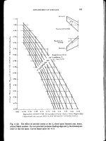
Fig.
4.33
shows the flexibility
of
high modulus vs. standard tape
282
Plastics Engineered Product Design
__1_1___
Figure
4-33
Dymetrol mechanical drive tape: (a) flexural modules and
(b)
beam flexure versus
tape thickness (unpunched)
TAPE
THICKNESS.
mi*lm.(w.
50
10
15
20
25
TAPE
15.2
x
1.9
m
-
6
x
3.9
rn
HOLE
-
8
rm
HOW
PrXH
'HIa
IIXIUWS.
DYWTWL
15.2
mm
vide
100
(0.60"
1
10.2
rm
wid.
(0.40")
400
B
e!
100
.
3
04-
LOO
a
0
a,.s ,
-40
-20
-0
20
40
60
80
lo@
2oro~mi(oo
(b)
O
TAPETMCIQIWS.rnlu
b
)
TeWCUTuD
coo
materials and
also
the effect of punching and of temperature on tape
stiffness. Naturally tape thickness and width
also
affect
a
tape's stiffness.
The obvious user benefit
of
this tape flexibility is greater versatility in
the design of energy transfer mechanisms, since allowing for push/pull
in non-linear modes, thereby advantageously replacing more complex
movement transmission devices such as lever arm systems, pulleys, or
gear systems. By using this feature, a cigarette vending machine offers a
5
0%
increase in brand choice without increase in machine dimensions.
Metal wire cable may rapidly fail in energy transfer mechanisms due
to
its frequently inadequate alternate flex cycle life, and spiral metal cable
due
to
its spiral collapse, these mechanical drive tapes have proved
to
be
extremely tough.
From these data, taken from various points of the tape's stress/strain
curve, it can be concluded that the strength of the mechanical drive
tapes. and in particular of the high modulus materials composition, is
appreciable and adequate indeed for the low
to
medium load transfer
service applications
to
which it addressed itself, and more than what is
needed for window regulators for instance. The user benefit here
naturally is long-term performance dependability or tape driven energy
transfer mechanisms and proved for instance by the low
GM
car after-
sale replacement rates of tape driven window regulators. Another
example is the. use of tape
to
drive outdoor venetian blinds in which
the previous drive device failed frequently causing expensive repair.
Contributing significantly
to
this tape toughness is its property
to
4
Product
design
283
recover from strain caused by permanent or intermittent operating
stress, even after exposure
to
temperatures as high as
80°C.
There is virtually no creep and very little permanent deformation.
Similar tests have hrthermore shown
that
there is not much more
deformation even after
8000
hours exposure
to
4000
psi. The
added
benefit of this
low
creep and strain recovery characteristic of tape is
that
it confers operating shock absorbency and smoothness
to
energy
transfer mechanisms, not or less provided by other energy transmission
devices since featuring steeper stress/strain characteristics or no
stress
elasticity
at
all.
Packaging
I_
-
Plastics are used
to
package many different forms and shapes of products.
Their performance requirements
are
very diversified ranging from
relatively
no
strength
to
extremely high strength, flexible
to
rigid, non-
permeable
to
permeable (in many different environments), and
so
on.
They require design performance requirements that include many
reviewed in this book. There is extensive literature on the subject of
packaging and
all
their ramifications.
Packaging industry and its technology is the major outlet for plastics
wherc it consumes about
30wt%
of
all
plastics (yearly sales above
$40
billion) with building and construction in second place consuming
about 20wt%. If plastic packaging were not
used,
the amount of
packaging contents (food, soaps,
etc.
)
discarded from
USA
households
would more than double. Plastics are the most efficient packaging
materials due
to
their higher product-to-package ratio as compared
to
other materials. One ounce
of
plastic packaging can hold about
34
ounces of product.
A
comparison of product delivered per ounce of
packaging material shows
34.0
plastics, 21.7 aluminum,
6.9
paper,
5.6
steel, and
1.8
glass.
When packaging problems
are
tough, plastics often
are
the answer and
sometimes the only answer. They can perform tasks no other materials
can and provide consumers
with
products and services
no
other
materials can provide.
As
an example plastics have extended
the
life
of
vegetables after they are packaged.
If plastic packaging were not used, the amount of packaging contents
(food, etc.) discarded from
USA
households would more than double.
Plastics are the most efficient packaging materials due to their higher
product-to-package ratio as compared
to
other materials.
One
ounce
of
284
Plastics Engineered Product Design
plastic packaging can hold about
34
ounces of product.
A
comparison
of product delivered per ounce of packaging material shows
34.0
plastics,
21.7
aluminum,
6.9
paper,
5.6
steel, and
1.8
glass.
Different designs and processing techniques are used
to
produce many
different packaging products. These different products show how
innovative designs have created different products based
on
plastic
behaviors and they’re processing capabilities. Most of these products
are extruded film and sheet that are usually thermoformed. Other
processes are used with injection molding and blow molding being the
other principal types used.
The largest market at
35%
of the total
is
for carded blister packs. The
second major product is window packaging at
24%.
The others are
clamshell packaging
at
20%, skin packaging at
18%,
and others at
3%.
The following information provides examples of packaging products
that meet different performance requirements that relates to the
capability of the plastic used:
aseptic
in food processing;
bag-in-box
refers
to
a sealed, sprouted plastic film bag inside a molded rigid
container;
beverage can
with aluminum cans dominating the
USA
market for
soft
drink containers with about
70%
of the market,
PET
plastic and glass compete for second place-note that most aluminum
cans have an inside coating, usually epoxy,
to
protect its contents fiom
the
aluminum;
beverage container
with carbonated
soft
drinks being the
largest market
at
about
50%
followed by beer at about
25%,
fruit juices
and drinks, and milk;
beer bottle
potential in bioriented stretched plastic
bottles in
USA
is on the horizon using coinjection or coextruded
plastics such as PET plastic and/or
PEN
plastic using various barrier
plastics or systems;
biological substance
that are classified as hazardous
requiring specialty packaging where plastics play an important role
to
meet strict requirements;
blister
also called blister carded packaging;
bubble pack
is plastic cushioning material used in packaging;
contour
packaging
is also called skin packaging;
dual-ovenable tray
are used for
frozen foods;
electronic packaging
with plastic ease of processing and
low cost has given them a wide application in solving problems in
electronic packaging;
film
breathable
identified as controlled-
atmospheric packaging (cap);
food packaging
with
plastics provides the
most efficient packaging materials due
to
their higher product-to-
package ratio as compared
to
other materials;
food
oxygen scavenger
impregnated plastics with chemically reactive additives that absorb
oxygen, ethyl, and other agents
of
spoilage inside the package once
it
has been sealed;
grocery bag; hot fill package
injection
&
blow molded
bottles, thermoformed containers, etc.;
modified atmosphere packagina
(mat) is
a
packaging method that uses special mixtures
of
gases
(carbon