Plastics Engineered Product Design 1 Episode 9 pptx
Bạn đang xem bản rút gọn của tài liệu. Xem và tải ngay bản đầy đủ của tài liệu tại đây (1.08 MB, 40 trang )
300
Plastics
Engineered Product Design
I
”
Figure
6.46
Schematic
of
strip
hybrids
ONE
WAY
STRIPS
TWO
WAY
STRIPS
they may be used jointly
to
satisfjr
two
or more design requirements
simultaneously, for example, fi-equency and impact resistance.
Comparable plots can be generated for other structural components.
such as plates or shells.
Also
plots can be developed for other behavior
variables (local deformation, stress concentration, and stress intensity
factors) and/or other design variables, (different composite systems).
This procedure can be formalized and embedded within a structural
synthesis capability
to
permit optimum designs
of
intraply hybrid
composites based on constituent fibers and matrices.
Low-cost, stiff, lightweight structural panels can be made by
embedding strips
of
advanced unidirectional composite (UDC) in
selected locations in inexpensive random composites. For example,
advanced composite strips from high modulus graphite/resin, intcr-
mediate graphite modulus/resin, and Keviar-49 resin can be embedded
in planar random E-glass/resin composite. Schematics showing
two
possible locations
of
advanced UDC strips in a random composite are
shown in Fig.
4.44
to
illustrate the concept.
It
is important
to
note that
the embedded strips do not increase either the thickness or the weight
of the composite. However,
the
strips increase the cost.
It
is important that the amount, type and location of
the
strip
reinforcement
be
used judiciously. The determination
of
all
of
these is
part of the design and analysis procedures. These procedures would
require composite mechanics and advanced analyses methods such as
finite element. The reason is that these components are designed
to
meet several adverse design requirements simultaneously. Henceforth,
planar random composites reinforced with advanced composite strips
will be called strip hybrids.
Chamis and Sinclair give
a
detailed
description of strip hybrids.
Here,
the discussion is limited
to
some
design guidelines inferred from several structural responses obtained by
using finite element structural analysis. Structural responses of panels
structural components can be used
to
provide design guidelines for
sizing and designing strip hybrids for aircraft engine nacelle, windmill
nuF:'
5
,:5
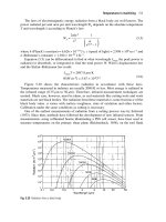
Structural responses
of
strip hybrid plates with fixed edges
2Bb
BY
VOL,
20
BY
20
BY
a05
in.
0-
hL
0
CONCENTRATED LOAD AT CENTER.
10
Ib
BUCKLING
Iblin.
LOAD,
,ok,
0
-21
I
I
0
20
40
0
2060
REINFORCING
STRIP
MODULUS, msi
BUCKLINC LOAD LOWEST FREO
blades and auto body applications. Several examples are described
below
to
illustrate the procedure.
The displacement and base material stress of the strip hybrids for
the
concentrated load, the buckling load, and the lowest natural fiequency
are plotted versus reinforcing strip modulus in Fig.
4.45.
As
can be seen
the displacement and stress and the lowest natural frequency vary
nonlinearly with reinforcing strip modulus while
the
buckling load
varies linearly. These figures can be used
to
select reinforcing strip
moduli for sizing strip hybrids
to
meet several specific design
requirements. These figures are restricted
to
square fixed-end panels
with
20%
strip reinforcement
by
volume. For designing more general
panels. suitable graphical data has to be generated.
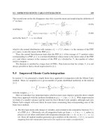
The maximum vibratory stress in the base material of the strip hybrids
due
to
periodic excitations with three different frequencies is plotted
versus reinforcing strip modulus in Fig.
4.46.
The maximum vibratory
stress in the base material varies nonlinearly and decreases rapidly
with
reinforcing strip modulus
to
about
103
GPa
(15
x
lo6
psi).
It
decreases
mildly beyond this modulus. The significant point here is that the
modulus of the reinforcing strips should be about
103
GPa
(15
x
lo6
psi)
to
minimize vibratory stresses (since they may cause fatigue
failures) for
the
strip
hybrids considered.
For
more general
strip
hybrids, graphical data with different percentage reinforcement and
different boundary conditions are required.
The maximum dynamic stress in the base material of the strip hybrids
302
Plastics Engineered Product Design
.46
Maximum stress in base material die to periodic vibrations
PERIODIC
FORCING
FREO,
ksi
I
\
\
cos
I
I
I
I
I
I
I
0
5
10
15
M
25
30 35
REINFORCING
STRIP
MODULUS.
msi
7
Maximum impulse
stress
at center
STRESS.
ksi
LT
9
IMPULSIVE FORCE
TRACE,
msec
0
5
10
15
20
25
30 35
cs-,8-37(10
REINFORCING STRIP MODULUS,
msi
due to an impulsive load is plotted in Fig.
4.47
versus reinforcing strip
modulus for
two
cases:
(1)
undamped and
(2)
with
0.009%
of critical
damping. The points to be noted from
this
figure are:
(a)
the dynamic
displacement varies nonlinearly with reinforcing strip modulus and
(b)
the damping is much more effective in strip hybrids with reinforcing
strip
moduli less than
103
GPa
(15
x
lo6
psi). Corresponding
displacements are shown in Fig.
4.48.
The behavior of the dynamic
displacements is similar
to
that of the stress
as
would be expected.
Curves
comparable to those in Figs
4.46
and
4.47
are needed
to
size
-l:~<a,(.
6
,it
Maximum impulse displacement
01
s
PLACEMENTS,
In.
IMPULSIVE
FORCE
TRACE.
mrec
0
5
10
I5
20
25
30
35
REINFORCING STRIP MODULUS,
msi
and design strip hybrid panels
so
that impulsive loads will not induce
displacements or stresses in the base material greater than
those
specified in the design requirements or are incompatible with the
material operational capabilities.
The
previous discussion and
the
conclusions derivcd thcrcfrom
were
based on panels of equal thickness. Structural responses for panels with
different thicknesses can be obtained from the corresponding responses
in Fig.
4.47
as follows (let
t
=
panel thickness):
1
2.
The buckling load varies directly with
9.
3.
The natural vibration frequencies vary directly with
t.
No
simple relationships exist for scaling the displacement and
stress
due
to
periodic excitation or impulsive loading.
Also,
all of
the
above
responses vary inversely with the square of the panel edge dimension.
Responses for square panels with different edge dimensions but with all
edges
fixed can be scaled from
the
corresponding curve in Fig.
4.45.
The significance of the scaling discussed above is that the curves in Fig.
4.45
can be
used
directly
to
size square strip hybrids for preliminary
design purposes.
The effects
of
a
multitude
of
parameters, inherent in composites, on the
structural response and/or performance of composite structures,
The displacement due
to
a concentrated static load varies inversely
with
t3
and the stress varies inversely with
9.
304
Plastics Engineered Product Design
and/or structural components are difficult
to
assess
in
general. These
parameters include several fiber properties (transverse and shear
moduli), in situ matrix properties, empirical or correlation factors used
in the micromechanical. equations, stress allowables (strengths),
processing variables, and perturbations of applied loading conditions.
The difficulty in assessing the effects of these parameters on composite
structural response arises from the fact
that
each parameter cannot be
isolated and its effects measured independently of the others.
Of
course, the effects of single loading conditions can be measured
independently. However. small perturbations of several sets of com-
bined design loading conditions are not easily assessed by measurement.
An
alternate approach
to
assess the effects of this multitude of
parameters is the use of optimum design (structural synthesis) concepts
and
procedures. In
this
approach the design
of
a composite structure is
cast as a mathematical programming problem. The weight or cost of
the structure is the objective (merit) function that is minimized subject
to
a given set
of
conditions. These conditions may include loading
conditions, design variables that are allowed
to
vary during the design
(such as fiber
type,
ply angle and number of plies), constraints on
response (behavior) variables (such as allowable stress, displacements,
buckling loads, frequencies, etc.) and variables that are assumed
to
remain constant (preassigned parameters) during the design.
The
preassigned parameters may include fiber volume ratio, void ratio,
transverse and shear fiber properties, in situ matrix properties, empirical
or correlation factors, structure size and design loads. Once the
optimum dcsign for a given structural component has been obtained,
the effects of the various preassigned design parameters on the optimum
design are determined using sensitivity analyses. Each parameter is
perturbed about its preassigned value and the structural component is
re-optimized. Any changes in the optimum design are a direct measure
of the effects
of
the parameter being perturbed. This provides a formal
approach to quantitatively
assess
the effects
of
the numerous parameters
mentioned previously on the optimum design
of
a structural component
and
to
identie which of the parameters studied have significant effects
on the optimum design of the structural component
of
interest. The
sensitivity analysis results
to
be described subsequently were obtained
using the angle plied composite panel and loading conditions as shown
in Fig.
4.49.
Sensitivity analyses are carried out
to
answer, for example, the following
questions:
1.
What
is
the
influence
of
the preassigned filament elastic properties
on the composite optimum design?
4
-
Product
design
305
Figure
4.49
Schematic
of
composite panel used in structural synthesis
2.
What is the influence of the various empirical factors/correlation
3.
Which of the preassigned parameters should be treated with care or
4.
What is the influence of applied load perturbations on the
The load system for the standard case consisted of three distinct load
conditions as specified in Fig.
4.49.
The panel used is
20
in.
x
16
in.
made from an
[(+e),],.
angle plied laminate. The influence
of
the
various preassigned parameters and the applied loads on optimum
designs is assessed by sensitivity analyses. The sensitivity analyses consist
of perturbing the preassigned parameters individually by some fixed
percentage of that value which was used in
a
reference (standard) case.
The
results obtained were compared
to
the standard case for comparison
and assessment of their effects.
Introductory approaches have been described
to
formally evaluate
design concepts
for
select structural components made fiom composites
including intraply hybrid composites and strip hybrids. These approaches
consist of structural analysis methods coupled with composite micro-
mechanics, finite element analysis in conjunction with composite
mechanics, and sensitivity analyses using structural optimization. Specific
cases described include:
1.
Hybridizing
ratio
effects on the structural response (displacement,
buckling, periodic excitation
and
impact) of a simply supported
beam made from intraply hybrid composite.
2.
Strip modulus effects on the structural response of a panel made
coefficients on the composite optimum design?
as design variables for
the
multilayered-filamentary composite?
composite optimum design?
306
Plastics Engineered Product Design
re
Graphite fiber
RP
automobile (Courtesy of
Ford
Co.)
PRODUCTION INSTRUMENT
PANEL
a
INTERIOR\
FRP FRONT SEAT
AME (BACK ONLY)
CTlON QUARTER
15GAL NYLON
OPENING PANEL
GrFRP REAR SUSPENSION
ARMS
-
UPR
a
LWR
NGAGED UPPER
3.
2
3L
14
ENGINE
C-3 AUTO TRANS
a
LOWER
CONTROL
ARMS
GRAPHITE COMPOSITES
TIRES
FR
78-14
(UNIQUE LIGHTWEIGHT)
LlGWTYElOHT
VEHICLE
DEPT
ENGlMERlNG
AND
RESEARCH
STAFF
from strip hybrid composite and subjected
to
static and dynamic
loading conditions.
Various constituent material properties, fabrication processes and
loading conditions effects
on
the optimum design of a panel subject
to
three different sets of biaxial in-plane loading conditions.
Automobile
Plastics play
a
very important role in vital areas of transportation
technology by providing special design considerations, process
freedom, novel opportunities, economy, aesthetics, durability, corrosion
resistance, lightweight, he1 savings, recyclability, safety, and
so
on.
Designs include lightweight and low cost principally injection molded
thermoplastic car body
to
totally eliminate metal structure
to
support
the body panels such as the concept in Fig.
4.50.
Other processes
include thermoforming and stamping. With more fuel-efficiency
regulation new developments in lightweight vehicles is occurring with
plastics. Plastics used include
ABS,
TPO,
PC,
PC/ABS,
PVC,
PVC/ABS,
PUR,
and
RPs.
Different cars, worldwide have been designed and fabricated such as
those
that follow.
(1)
Chrysler’s light-weight (50wt% reduction)
Composite Concept Vehicle (CCV) uses large injection molded glass
fiber-TP structural body panels with only a limited amount of metal
underneath/assembled by adhesive bonding
or
fusion welding.
(2)
Ford has plastic parts in its 2001 Explorer Sport Trac sport utility
vehicle replaces the steel open cargo area with
RP (SMC), and other
cars.
(3)
Daimler-Benz's (Stuttgart, Germany) light-weight 2-seat
coupe, called the Smart car, has injection molded outer body
panels/unitizes TP body ties together the front fender, outer door
panels, fiont panels, rear valence panels, and wheel arch in
one
wrap-
around package.
(4)
GM focusing
with
plastics in their electric vehicle.
(5)
Asha/Taisun of Singapore producing taxi cabs for China with
thermoformed body panels mounted on a tubular stainless steel space
frame.
NA
Bus Industries of Phoenix is delivering buses in
USA
and
Europe with all
RP
bodies. Brunswick Tech. Inc. of Brunswick, ME
produces-weight30
fi
RJ?
buses except for the metallic engine. Sichuan
Huatong Motors Group's (Chengdu, China) 4-door/5-passenger
midsize vehicle all-plastic car, called Paradigm, has glass fiber-TS
polyester
RP
sandwich chassis and thermoformed coextruded
ABS
body panels/chassis features single thermoformed lower tub and an
upper skeleton X-brace roof/monocoque structure where body panels
are stitched-bonded to the chassis, forming a unitized structure.
Truck
Since mid
1040s
plastics and
RPs
have been used in trucks and trailers.
In use are long plastic floors, side panels, translucent roofs, aeronautical
ovcr-thc-cabin structures, insulated refrigerated trucks, etc. (that were
initially installed on Strick Trailers by DVR during the late
1940s).
The
lighter weight plastic products permitted trailers to carry heavier loads,
conserve
fuel,
refrigerated trucks traveled longer distance (due
to
improved heat insulation), etc. Different plastics continued
to
be used
in the different truck applications
to
meet static and dynamic loads that
includes high vibration
loads.
Pickup trucks make use of
100
Ib
box
containers using TPs and for the tougher requirements
RPs
are used.
Aircraft
Plastics continue
to
expand their use in primary and secondary
aeronautical structures that include aircraft, helicopters,
and
balloons,
to
missiles
space structures. Lightweight durable plastics
and
high
performance reinforced plastics
(RPs)
save on fuel while resisting
all
kinds
of static and dynamic loads (creep, fatigue, impact, etc.)
in
different and
extreme environments. Certain military planes contain up
to
60wt%
308
Plastics Engineered Product Design
ure
4.51
McDonald-Douglas
AV-8B
Harrier plastic parts (Courtesy
of
McDonald-Douglas)
0
Aluminum
Titanium
0
Other
Horizontal
stabilizer
(full span),
Composites
Wing Skin
(full
span)
Outriaaer
\
"/
Flap slot door
/?,
Aileron
I/
Seals
id fence
nd strakes
\Sine wave
spars and ribs
Fotward fuselage
plastics. Other airplanes take advantage of plastics performances such as
the
McDonald-Douglas AV-8B Harrier with over
26
%
of this aircraft's
weight using carbon fiber-epoxy reinforced plastics; other plastics also
used (Fig. 4.51). Aircraft developments
at
the present time
are
extensively using cost-effective reinforced plastics and hybrid composites.
A historical event occurred during
1944
at
U.
S.
Air Force, Wright-
Patterson
AF
Base, Dayton, OH with
a
successful all-plastic airplane
(primary and secondary structures) during its first flight. This
BT-19
aircraft was designed, fabricated, and flight-tested in the laboratories of
WPEFB using
RPs
(glass fiber-TS polyester hand lay-up that included
the use
of
the
lost-wax process sandwich constructions for the
fabrication of monocoque fuselage, wings, vertical stabilizer, etc.
Sandwich (cellular acetate foamed core) construction provides meeting
the static and dynamic loads that the aircraft encountered in flight and
on the ground. This project was conducted in case the aluminum that
was used to build airplanes became unavailable. The wooden airplane,
the
Spruce
Goose
built by Howard Hughes was also a contender for
replacing aircraft aluminum.
Extensive material testing was conducted
to
obtain new engineering
data applicable
to
the
loads the sandwich structures would encounter;
4
.
Product
design
309
.52
Example of orientation of fibers (fabrics)
in
the all-plastic airplane wing
construction
data was extrapolated for long time periods. Short term creep and
fatigue tests conducted proved
to
be exceptionally satisfactory. Later
50
of this
type
of aircraft were built by Grumman Aircraft that also resulted
in more than satisfactory technical performance going through
different maneuvers.
In order
to
develop and maximize load performances required in the
aircraft structures, glass fabric reinforcement laminated construction
(with varying thickness) was oriented
in
the required patterns (Chapter
2).
Fig.
4.52
shows an example of the fabric lay-out pattern for the wing
structure.
It
is
a
view of
a
section of the wing after fabrication and ready
for attachments, etc.
Developments
of
aircraft turbine intake engine blades
that
started
during the early
1940s
may now reach fulfillment. Major problem in
the past has been
to
control the expansion of the blades
that
become
heated during engine operation. The next generation of turbine fan
blades should significantly improve safety and reliability, reduce noise,
and lower maintenance and fuel costs for commercial and military
planes because engineers will probably craft them from carbon fiber
RJ?
composites. Initial feasibility tests by University of California
at
San
Diego (UCSD) structural engineers,
NASA,
and the U.S. Air Force
show these carbon composite fan blades are superior
to
the metallic,
titanium blades currently used.
Turbine fan blades play
a
critical role in overall functionality of an
airplane. They connect
to
the turbine engine located in the nacelle,
a
3
10
Plastics Engineered Product Design
large chamber that contains wind flow to generate more power. These
usually
6
ft
long blades create high wind velocity and
80%
of the plane’s
thrust.
It
is reported that the leading cause of engine failure is damaged
fan
blades. Failure may occur fiom thc ingestion of external objects, such as
birds,
or
it may be related
to
material defects. If it’s a metallic blade and
it breaks,
it
can tear through the nacelle as well as the fuselage and
damage fuel lines and control systems. When this happens, the safety of
the aircraft and its passengers is threatened, and the likelihood of a
plane crash increases.
In contrast, if an
RP
blade breaks, it simply crumbles to bits and does
not pose a threat
to
the structure of the plane. However, breakage is
less likely because composite materials are tougher and lighter than
metallic blades and exhibit better fatigue characteristics.
A
multiengine
plane can shut down an engine and continue
to
fly
if a blade is lost and
no
other damage has occurred.
A
composite blade disintegrates into
many small pieces because it is reallyojust brittle graphite fibers held
together in a plastic.
A
titanium blade, however, will fail at the blade
root,
causing large,
4-
to
6-foot blades
to
fly through the air.
As
designed, the
RP
blades are essentially hollow with
an
internal rib
structure. These rib like vents direct, mix, and control airflow more
effectively which reduces the amount of energy needed
to
turn the
blades and cuts back
on
noise. Most engine noise actually comes from
wind turbulence that collides with the nacelle.
By
directing air out the
back
of
the fan blades, the noise can be reduced by
a
factor of
two.
And
by drawing more air into the blades, engine efficiency is improved by
20%.
There also exists embedded elastic dampening materials in the blades,
which minimizes vibrations
to
improve resiliency. Because the blade is
lighter and experiences lower centrifugal forces, hrther enhanced the
blade’s durability occurs. Small-scale wind tunnel tests show they last
10
to
15
times longer than any existing blade. The
No.
1
maintenance
task is the constant process of taking engines apart
to
check the blades.
These
new
blades should lend themselves
to
more efficient production
techniques. If you use titanium, you need
to
buy a big block of
it
and
machine it down
to
size, wasting a
lot
of material.
As
reported, this is
very time consuming, and
one
has
to
worry about thermal warping.
The
RP
allows for mass production. It is fabricated into
a
mold, making
thc process more precise and ensuring the blades are identical.
NASA
will test the new blades in large-scalc wind tunnels
at
the
NASA
Glenn
Research Center in Cleveland. If successfid, they could
see
installation
by
2004.
Ovcr
the
years innovations in aircraft designs have given rise
to
more
new plastic developments and have kept the plastics industry profits at a
higher level than any other major market principally since they can meet
different load and environmental conditions. Virtually all plastics have
received the benefit of the aircrafi industry’s uplifting influence.
Marine Application
From ships
to
submarines
to
mining the sea floor worldwide, certain
plastics and
RPs
can survive the sea environment. This environment can
be considered more hostile than that on earth or in space. For water
surface vehicles, many different plastics have been used in designs in
successful products in both fresh and the more hostile seawater. Boats
have been designed and fabricated since at least the
1940s.
Anyone can
nom7 observe that practically all boats, at least up
to
9
m
(30
fi)
are
made from RPs that are usually hand lay-up moldings from glass
rovings, chopper glass pray-ups, and/or glass fiber mats with TS
polyester resin matrices. Because of the excellent performance of many
plastics in fksh and sea water, they have been used in practically all
structural and nonstructural applications from ropes
to
tanks
to
all
kinds of instrument containers.
Boat
In addition
to
their use in boat hull construction, plastics and
RPs
have
been used in a variety of shipboard structures (internal and external).
They are used generally
to
save weight and
to
eliminate corrosion
problems inherent in the use of aluminum and steel or other metallic
constructions.
Plastic
use
in boat construction is in both civilian and military boats
[28
to
188
fi.
(8.5
to
55
m)]. Hulls with non-traditional structural shapes
do
not have longitudinal or transverse framing inside the hull. Growth
continues where
it
has been dominating in the small boats and
continues with the longer boat boats. The present big boats that are at
least up
to
188
fi
long have been designed and built in different
countries
(USA,
UK,
Russia, Italy, etc.). In practically all of these boats
low
pressure
RP
molding fabrication techniques were used.
Examples of a large boat are the
U.S.
Navy’s upgraded minehunter
fleet, the “Osprey” class minehunter that withstands underwater
explosions. Design used longitudinal or transverse framing inside the
piece hull.
It
has a one piece
RP
super structure. Material of
construction
used
was glass fiber-TS polyester plastic. The designer and
fabricator was Interimarine S.P.A., Sarzana, Italy. The unconventional,
3
1
2
Plastics Engineered Product Design
Figure
4.53
Examples
of
materials
for
deep submergence vehicles
unstiffened hull with its strength and resiliency was engineered
to
deform elastically as it absorbs
the
shock waves of
a
detonated mine. Its
design requirements included
to
simplify inspection and maintenance
from within
the
structure.
Underwater
Hdl
On
going
R&D
programs continue to be conducted for deep
submergence hulls. Materials of construction are usually limited
to
certain steels, aluminum, titanium, glass, fiber
RPs,
and other
composites (Fig.
4.53).
There
is
a factor relating material’s strength-to-
weight characteristics
to
a geometric configuration for
a
specified
design depth. Ratio showing the weight of the pressure hull
to
the
weight of the seawater displaced
by
the submerged hull is the factor
referred
to
as
the
weight displacement
(W/D)
ratio. Submergence
materials show
the
variation of the collapse depth of spherical hulls with
the
weight displacement of
these
materials.
All
these materials, initially,
would permit building the hull
of
a
rescue vehicle operating
at
1800
m
(6000
fi)
with
a collapse depth of
2700
m
(9000
ft).
When analyzing materials for an underwater search vehicle operating at
6000
m
(20,000
fi)
with collapse depth of
9000
m
(30,000
fi),
metals
are not applicable. Materials considered are glass and
RP.
The strength-
to-weight values for metals potentially are not satisfactory. One
of
the
advantages of glass is its high compressive strength; however, one
of
its
major drawbacks is its lack of toughness and destructive effect
if
any
twist, etc. occurs other
than
the compression load.
It
also has difficulty
if the design requires penetrations and hatches in the glass
hull.
A
solution could be filament winding
RP
around the glass or using a
4
-
Product
design
31
3
tough plastic skin.
These glass problems show
that
the
RP
hull is very attractive on weight-
displacement ratio, strength-weight ratio, and for its fabrication
capability. By using the higher modulus and lower weight advanced
designed fibers (high strength glass, aramid, carbon, graphite, etc.)
additional gains will occur.
Depth limitations of various hull materials in near-perfect spheres
superimposed the familiar distribution curve of ocean depths.
To
place
materials in their proper perspective, as reviewed, the common factor
relating
their
strength-to-weight characteristics
to
a
geometric con-
figuration for
a
specified design depth is the ratio showing the weight of
the pressure hull
to
the
weight of the seawater displaced by the
submerged hull. This factor is referred
to
as the weight displacement
(W/D) ratio. The portions the vehicles above the depth distribution
curve correspond to hulls having a
0.5
W/D ratio; portion beneath
showing the depth attainable by heavier hulls with a
0.7
W/D.
Based on test programs the ratio of
0.5
and
0.7
is not arbitrary. For
small vehicles they can be designed with W/D ratios of
0.5
or less, and
vehicle displacements can become large as their W/D approach
0.7.
Ry
using this approach these values permits making meaningful compari-
sons of the depth potential for various hull materials. With the best
examination data reveals that for the metallic pressure-hull materials,
best results would permit operation to
a
depth of about 18,288 m
(20,000
ft)
only
at
the expense of increased displacement.
RPs
(those
with just glass fiber-TS polyester plastic) and glass would permit
operation
to
20,000
fi
or more with minimum displacement vehicles.
The design of a hull is a very complex problem. Under varying sub-
mergence depths there can be significant working of the hull structure,
resulting in movement of the attached piping and foundation. These
deflections, however slight, set up high stresses in the attached
members. Hence, the extent
of
such strain loads must be considered in
designing attached components.
Missile
and
Rocket
Different plastics, particularly high performance plastics and
Rl's
are
required in missiles
(Fig.
4.54)
and rockets as well as outer space
vehicles. Parts in
a
missile are very diverse ranging from structural and
nonstructural members, piping systems, electrical devices, exhaust
insulators, ablative devices, personnel support equipment, etc.
3
14
Plastics Engineered Product Design
Missile in flight includes the use
of
plastics
ll_ _l~l-l
__I_
-^
El
ectri ca
I/E
I
ectro
n
ic
-
.
-
I
-
a*''-
With the diverse electrical properties of plastics, extensive use of plastics
has been made since the first plastics was produced. Plastics permits the
operation of many electrical and electronic devices worldwide.
As
it has
been said many times most of the electrical/ electronic equipment and
devices used and enjoyed today would not be practical, economical,
and/or some even possibly exist without plastics. Plastics offer the
designer a great degree of freedom in the design and particularly the
fabrication of products requiring specific electrical properties and
usually requiring special and accurately fabricated products. Their
combination of mechanical and electrical properties makes them an
ideal choice for everything from micro electronic components and fiber
optics
to
large electrical equipment enclosures.
Development
of
many different polymers and plastic compounds (via
additives, fillers, and reinforcements) continues
to
expand the
use
of
plastics in electrical applications. By including fillers/additives, such
as
glass in plastics, electrical properties can considerably extend perfor-
mances
of
many plastics (Fig.
4.55).
The electrical propcrtics of plastics vary from being excellent insulators
to
being quite conductive in different environments. Depending
on
the
application, plastics may be formulated and processed
to
exhibit a single
property or a designed combination
of
electrical, rncchanical, chemical,
r-
-
Dielectric
constant
%
additives
or
fillers
3
1
6
Plastics Engineered Product Design
thermal, optical, aging properties, and others. The chemical structure
of polymers and the various additives they may incorporate provide
compounds
to
meet many different performance requirements.
Plastic provides ideas for advancing electrical and electronic systems
&om conducting electricity to the telephone to electronic communication
devices. Thousands of outstanding applications use plastics in electrical
products. The users’ and designers’ imaginations have excelled in
developing new plastic products.
Shielding Elect
ri
ca
I
Device
With the extensive use of plastics in devices such as computers, medical
devices, and communication equipment the issue of electromagnetic
compatibility
(EMC)
exists that in turn relate
to
electromagnetic
interference
(EMI)
and
radio-frequency interference
(RFI).
EMC
identifies types of electrical device’s capability
to
hnction
normally without interference by any electrical device. These devices are
designed to
minimize
risks associated
with
reasonably foreseeable environ-
mental conditions. They include magnetic fields, external electrical
influences, electrostatic discharge, pressure, temperature, or variations
in pressure and acceleration, and reciprocal interference with other
devices normally used in investigations or treatment.
EM1
or
RFI
as well as static charge
is
the
interference related
to
accumulated electrostatic charge in a nonconductor.
As
electronic
products become smaller and more powerful, there is a growing need
for higher shielding levels
to
assure their performance
and
guard against
failure. From
the
past
40
dB
shielding,
the
60
dB is becoming the
normal higher value. There is
EM1
shielding-effectiveness
(SE)
that
defines the ratio of the incident electrical field strength
to
the
transmitted electrical field strength. Frequency range is from
30
MHz
Many plastics are electrical insulators because they are nonconductive.
They do not shield electronic signals generated by outside sources or
prevent electromagnetic energy from being emitted &om equipment
housed in a plastic enclosure. Government regulations have been set up
requiring shielding when the operating frequencies are greater than
10
kHz.
The plastic shielding material used may include the use
of
additives.
Designs may include board-level shielding of circuit, bondable gaskets,
and locating all electrical circuits in one location
so
only that section
requires appropriate shielding. Designers of enclosures for electronic
to
1.5
GHz
(ASTM
D
4935-89).
4
.
Product
design
31
7
-
devices should be aware of changes in EMC that tend
to
continually
develop worldwide.
Conductive plastics provide EMI/RFI shielding by absorbing
electromagnetic energy (EME) and converting it into electrical or
thermal energy. They also function by reflecting EME. This action
ensures operational integrity and EMC with existing standards.
Conductive plastics are generally designed
to
meet specific performance
requirements (physical, mechanical, etc.) in addition to EMI/RFI or
static control. Often these plastics have
to
perform structural functions,
meet flammability or temperature standards, and provide wear or
corrosive resistant surfaces, etc.
The usual plastics alone lack sufficient conductivity
to
shield EM1 and
RFI
interference. Designers can reduce or eliminate sufficiently electro-
magnetic emissions from plastic housings like those of medical devices
and computers just by shielding the inner emission sources with metal
shrouds in the so-called tin can method. The same effect can be
obtained by designing electronics to keep emissions below standard
limits or by incorporating shielding into the plastic housing itself.
Designers will often employ all these strategies in a single design. What
is
most important is to attempt
to
locate
all
the shielding in
a
relatively
small volume within the larger housing and then tin can it to provide
a
simplified solution rather than spreading it out.
Every electronic system has some level of electromagnetic radiation
associated
with
it. If
this
level is strong enough to cause other
equipment
to
malfunction, the radiating device
will
be
considered
a
noise source and usually subjected
to
shielding regulations. This is
especially true when EM1 occurs within the normal fkequencies of
communication.
When
the electronic noise is sufficient to cause
malfbnctioning in equipment such as data processing systems, medical
devices, flight instrumentation, traffic control, etc. the results could
prove damaging and even life threatening. Reducing the emission of
and susceptibility
to
EM1
or
radio fkequency interference (RFI)
to
safe
levels is thus the prime reason to shield medical devices (and other
devices) in whatever type of housing exist, including plastic.
In addition to compounding additives for shielding, there
is
the
technology of applying conductive coatings, such as vacuum systems or
paint systems (sprays, etc.). Other methods include the use of
conductive foils or molded conductive plastics, silver reduction, vacuum
metalization, and cathode sputtering. Although zinc-arc spraying once
accounted for about half the market, others have surpassed it. Other
conductive coatings are also used. Unlike other shielding methods,
31
8
Plastics Engineered Product Design
conductive coatings are usually applied
to
the interiors of housings and
do not require additional design efforts to achieve external aesthetic
goals.
All
systems offer trade-offs in shielding performance, the physical
properties of the plastics, ease in production, and cost.
Designers have
to
confirm the suitability of
a
material’s shielding
performance for each system through such conventional means as
screen-room or open-field testing. Each approach
to
shielding should
also be subjected
to
simulated environmental conditions,
to
determine
the shield’s behavior during storage, shipment,
and
exposure
to
humidity. Some times comparison of shielding materials becomes
difficult. ASTM has a standard that defines the methods for stabilizing
materials measurement, thus allowing relative measurements
to
be
repeated in any laboratory. These procedures permit relative
performance ranking,
so
that comparisons of materials can also be
made.
Organizations involved in conducting and/or preparing specifications/
standards
on
the electrical properties on plastics include the Under-
writers Laboratories
(UL),
American Society for Testing and Materials
(ASTM), Canadian Standards Association (CSA), International
Electrotechnical Commission (IEC), International Organization for
Standardization
(ISO),
and American National Standards Institute
UL
has a combination of methods for environmental conditioning and
adhesion testing
to
evaluate various approaches
to
shielding and
to
determine the plastic
types
that are suitable. The primary concern is
safety. Should
a
metalized plastic delaminate or chip off, an electrical
short is formed
that
could cause
a
fire.
(ANSI).
Radome
Radome (radiation dome) is used
to
cover
a
microwave electronic
communication antenna.
It
protects the antenna from the environment
such as the ground, underwater, and in the air vehicles.
To
eliminate
any transmission interference, it would be desirable not
to
use
a
radome
since transmission loss of up
to
5%
occurs with
the
protective radome
cover material. The radome is made
to
be as possibly transparent
to
electromagnetic radiation and structurally strong. Different materials
can be used such as plastics, wood, rubber-coated air-supported fabric,
etc.
To
meet structural load requirements such as an aircraft radome
to
ground radomes subjected
to
wind loads,
use
is made of
RPs
that are
molded
to
very tight thickness tolerances. Fig.
4.56
shows
a
schematic
of
a
typical ground radome that protects an antenna from the
4
-
Product
design
31
9
~~
_I_
%I
5
Antenna
(1
50ft) protected
by
a plastic radome
environment (withstand over
150
mph winds and temperatures from
arctic
to
tropical conditions, sand/dirt, etc.) using RP-honeycomb
sandwich curved panels This schematic represents protecting in service
150
ft
(46
m) antennas. Since
that
time the most popular is the use of
glass fiber-TS polyester
RPs.
The shape of
the
dome, that is usually
spherical, is designed not
to
interfere with the radiation transmission.
The
use
of
the secondary load structure
RP
aircraft radomes have been
used since the early
1940s.
At
that
time
the
problem of rain erosion
developed on their front of
the
radome.
It
first appeared on
the
RP
“eagle wing” radome located below the
B-29
bomber aircraft.
It
had
an
airfoil-shaped radome that was
6
m
(20
ft)
long located about
0.5
m
(1
1
ft)
below its wing. On its initial flight over the Pacific Ocean upon
encountering rain,
the
RP
radome (and its radar capacity) was completely
destroyed.
This
introduced the era of rain erosion damage
to
plastics
in
using
a
rain erosion elastomeric plastic coating (Chapter
2).
320
Plastics Engineered Product Design
Medical
Plastic devices of all types have become vital in the medical industry.
Products range from disposables (medical supplies, drug delivery
devices, ointments, etc.
)
to non-disposables and packages
to
containers
to
body parts. Packaged drugs include premeasured single-dose
disposable units. The diversified properties and behaviors of plastics
have developed into an important market for plastics.
Plastic applications are very diversified ranging fiom band-aids
to
parts
of
the heart. Many examples exist
in
addition
to
those being reviewed.
1.
Abiomed (Danvers,
MA)
is
the
manufacturer of the self-contained
artificial heart. Of the six patients who received the grapefiuit-sized
plastic and titanium heart, three remain alive
(2003).
2.
Developments have found certain plastics existing in the environ-
ment
of
living tissues.
3.The heart valve that is often used in surgery
to
correct heart
deficiencies was
a
contribution to medicine. In order for it to be
successful it required ingenuity in design that would fbnction as
a
replacement for
the
mitral valve
and
to
perform as
weil
as the one
replaced long enough
to
justie the risk involved
in
the operation.
It
also included using a bioplastic material that would function in the
highly complex environment
of
the human circulatory system with-
out being degraded and without causing harm to the circulatory
system.
4.Many developments occur in the area of implants that include the
use of plastics. Examples include pacemaker, surgical prosthesis
devices
to
replace limbs, use
of
plastic tubing
to
support damaged
blood vessels, and work with the portable artificial kidney.
5.There are applications based on the membrane qualities of plastics.
They can control such
things
as
the
chemical constituents that
pass
from one part of a system
to
another,
the
electrical surface potential
in
a system, the surface catalytic effect on a system, and in some cases the
reaction
to
specific
influences such
as
toxins
or
strong radiation.
6.
Polyelectrolytes plastics are chemically active. They have been used
to make artificial mechanical power muscle materials. They create
motion by
the
lengthening and shortening
of
fibers made
fiom
the
chemically active plastic by changing the composition
of
the
surrounding liquid medium, either directly or by the use of
electrolytic chemical action.
It
is
no a competitor
to
thermal energy
sources, but it is potentially valuable in detector equipment that
4
Product
design
321
-
would be sensitive
to
the changing composition of
a
water stream or
other environmental flow situation.
7.There is
the
application of extruded high- and low-pressure plastic
balloons used in angioplasty catheters.
Use
of these balloons has
extended
into
many applications such
as
other catheters (dilatation,
heat transfer, laser, cryogenic, etc.), photodynamic therapy devices,
drug delivery devices, etc.
8.Plastics in bioscience have potential
to
be used for mechanical
implants in living systems (includes animals and plants) where they
can serve as repair parts or as modifications of the system.
9.
Kidney applications involve more than the mechanical characteristics
of potential plastic
use.
The kidney machine consists of large areas
of
a
semi-permeable membrane, a cellulosic material in some
machines, where the kidney toxins are removed from the body
fluids by dialysis based on the semi-permeable characteristics
of
the
plastic membrane. Different plastics are being study for use in this
area, but the basic unit is a device
to
circulate
the
body fluid
through the dialysis device
to
separate toxic substances fiom the
blood.
The
mechanical aspects of the problem are minor but do
involve supports for the large amount
of
membrane required.
10.Surgical implants are essentially plastic repair parts for worn out
parts of the body.
It
is possible
to
conceive of major replacements
of
an entire organ such as a kidney or a heart by combining the plastic
skills
with
tissue regeneration efforts that may extend life. This is
used
to
time
the
heart action. Extensively used are plastic
corrugated, fiber (silicone or
TP
polyester) braided aortas.
11. Different customized developments exist and are being used.
An
example is
a
porous (foam
type)
ultrahigh-molecular-weight
poly-
ethylene
(UHMWPE)
that
is an FDA-compliant material. Its
porosity
and
pore size can be adjusted per the end-users’
requirements. The porosity is uniform in
all
three
(X,
Y,
Z)
axes,
which is vital
to
constant liquid flow in filtration and separation.
It
is
already used in
a
wide range of medical and laboratory filtration and
separation applications by providing customizing processing where
chemical
purity
of the material is maintained (no additives
are
used).
UHMWPE
is
a chemically resistant, long-chain polymer of ethylene
with an extremely high molecular weight
of
3.1
million amu
or
above. Because of its high molecular weight, the polymer maintains
abrasion resistance and
strength
even when
it
is made porous for
filtration or separation applications. The porous form, which can be
pleated, is easily handled in manufacturing.
It
can be precision skived
322
Plastics Engineered Product Design
into films as thin as
0.002
in. (skiving consists of shaving off a thin
film layer from a large block of solid plastic, usually a round billet).
Doctors with long, intensive training as basic scientists make them
uniquely suitable as product designers. They become involved in
designing new products that in turn could require the plastic industry
in developing new/modified plastics. With all this action in developing
medical products and devices the
FDA
usually requires approval that
takes time.
Surgical Product
The wide range of forms (film, tube, or fiber) and mechanical
properties available in plastics continues
to
make them attractive
candidates for such uses (Fig.
4.57).
These plastics are required
to
possess desired physical/mechanical properties and the assurance that
they may be successfully utilized in the body.
To
be successful plastic
implants involve the cross-fertilization of different disciplines (chemists,
designers, physician, fabricator, etc.).
Developing of surgical implants confronts major problems because
human bodies have extremely complex environments. They could be
identified as having the most horrible environmental situation on earth.
In addition different human bodies have different environmental require-
ments. Thus what can survive in one body usually does not survive in
other bodies. This type of reaction requires extensive R&D
to
ensure
that a medical product can survive and meet its requirements in all
human or specific bodies.
Dental Product
Dentures continue
to
be an important and major market for plastics.
Use
is made of acrylics
(PMMAs)
that includes
full
dentures, partial
dentures, teeth, denture reliners, fillings and miscellaneous
uses.
PMMAs
provide strength, exceptional optical properties,
low
water
absorption and solubility, and excellent dimensional stability. In the past
plastics used included nitrocellulose, phenol-formaldehyde, and vinyls
as denture base materials. Results, however, were not satisfactory
because these plastics did not have the proper requisites of dental
plastics. Since then,
PMMAs
have kept their lead as the most useful
dental plastics, although many new plastics have appeared
and
othcrs
are being tested.
Todate plastics are not very usehl as filling materials with only about
2wt%
of all fillings using plastics. The low mechanical properties
of
Ithi*
.
~
*‘
:”:
Examples
of
surgical implants
(Courtesy
of
Plastics
FALLO)
1.
LENS IMPLANT
2.
CONTACT LENS
3.
IN
VIVO ARTIFICIAL
HEARINO SYSTEM
4.
DENTAL STRUCTURES
5. EXTERNAL PROTHESIS
6.
ARTIFICIAL LARYNX
7.
ARTIFICIAL SKIN
8. HEART VALVES
0.
ARTIFICIAL HEART
IO.
KIDNEY-DIALYSIS SYSTEM
11.ARTIFICIAL BLOOD
12. INTRAAORTIC BALLOON
13. ANGIOPLASTY CATHETER
14.
VASCULAR QRAFTS
15. SUTURES
16.
POSTMASTECTOMY
17.
ARTIFICIAL HIP, KNEE
18. ARTIFICIAL FINGER,
19.
TORN LIGAMENTS
20.
NATURAL-ACTION FOOT
21. AORTA
TOE
JOINTS
plastics in comparison with metals limit their application where stresses
are great.
It
is
interesting
to
note development efforts has taken place in
the
use
of whiskers for reinforcing dental plastic, metal,
and
ceramic
fillings. Some preliminary test results on the addition
of
randomly
distributed chopped, short whiskers
to
a coating plastic have reversed
the
previous proportional loss
of
strength with powder additions.
Although this is far from theoretical, it is already quite significant in that
it allows
the
addition
of
pigment
for
coloring purposes and
a
restoration
of
the loss
of
strength with whisker additions.
324
Plastics Engineered Product Design
Health
Care
Here they have made many major contributions
to
the contemporary
scene. Health-care professionals depend
on
plastics for everything from
intravenous bags
to
wheelchairs, disposable labware
to
silicone body
parts, and
so
on.
The diversity
of
plastics allows them
to
serve in many
ways, improving and prolonging lives [such as
a
braided, corrugated
(Du
Pont’s Dacron polyester) TP aorta tube].
Thousands of biodegradable plastics have been analyzed.
An
example is
at
the Massachusetts Institute of Technology (MIT) test program that
may save lives in the form
of
a medical implant. Tests include its
effectiveness as a drug-releasing implant in brain cancer patients, These
implants, roughly the size of
a
quarter, are being placed in patients’
brains
to
release the chemotherapy drug BCNU (Carmustine). Todate
these biocompatible implants have been found
to
be safer
than
injections, which can cause the BCNU
to
enter the bone marrow or
lungs, where the drug is toxic.
Use
is being made of the polyanhydride plastic that was designed
shapewise
so
that water would trigger its degradation but would not
allow
a drug
to
be released all
at
once. The implant degrades from the
outside, like a bar of soap, releasing the drug at a controlled rate even as
it becomes smaller. The rate at which the drug is released is determined
by the surface shaped area of the implant and the rate of plastic
degradation that is customized
to
release drugs
at
rates varying from
one
day
to
many years. This design approach also holds promise for use
with different drugs for various other-medical systems. Interesting
that
in the past these plastics were used with explosives for
use
in
a
war.
When
the plastic degraded by water or sunlight, the device would
explode.
Recreation
Plastics provide structurally sound, durability, and safe equipment for
sports and recreation facilities. The broad range of properties available
from plastics has made them part of all
types
of sports and recreational
equipment worldwide for land, water, and airborne activities. Roller-
skate wheels have become abrasion- and wear-resistant polyurethane,
tennis rackets are molded
from
specially reinforced plastics (using glass,
aramid, graphite, and/or hybrid fibers),
skis
are laminated
with
RPs,
RP
pole-vaults extensively used
to
go
“higher”, and many more.