HANDBOOK OF CARDIAC PACING – PART 7 pdf
Bạn đang xem bản rút gọn của tài liệu. Xem và tải ngay bản đầy đủ của tài liệu tại đây (287.3 KB, 16 trang )
88 Handbook of Cardiac Pacing
10
Ta b le 10.3. Common postoperative orders
1. PA and Lateral chest X-ray within 2 hrs for lead placement and to evaluate for
pneumothorax
2. Ice pack to incision site
3. IV antibiotics (usually one additional dose)
4. Oral and parenteral analgesics
5. Maintain head of bead > 30° angle
6. Resumption of diet
7. Vital signs frequently at first then tapering to routine
8. Wound dressing check for drainage and hematoma
9. Respiratory status evaluation (for pneumothorax)
10. Monitor ECG rhythm for arrhythmias, capture and appropriate sensing
11. Restrict movement of ipsilateral arm for 24 hours
12. Full pacemaker evaluation prior to discharge with activation of any special features
and adjustment of the sensor if present
Ta b le 10.4. Predischarge teaching
Wound care instructions include the following:
1. Continually assess wound for signs and symptoms of infection.
2. Keep wound clean and dry for 1 week.
3. Cover the incision with plastic when bathing.
4. Remove steri-strips after 7 days. Do not wait until they fall off.
Activity restrictions:
1. No lifting greater than 10 pounds for 2 weeks.
2. No repetitive arm extension over the head for 2 weeks.
3. If the patient is pacemaker dependent, driving should be restricted for 2 weeks
or as determined by the physician. Otherwise, 48 hours is usually sufficient to
allow the patient to recover from any anesthesia and for the incisional pain to
subside
Restrictions against electromagnetic interference:
1. Arc welding
2. MRI
3. Diathermy
4. Therapeutic radiation over the pacemaker
5. Electronic article surveillance scanners
6. Metal detectors
7. Supermarket checkout scanners
8. Cell phones
9. Electric blankets
Contact the pacemaker clinic if:
1. Symptoms prior to implant return
2. The pulse rate seems too slow or too fast
3. Dizziness, lightheadedness, or syncope occurs
4. Unusual shortness of breath or chest pain develops
5. Muscle twitching around the pacemaker is present
89Preoperative, Operative and Postoperative Considerations
10
Virtually all household electrical items and power tools are safe for patients to
use. Sources of high electrical energy, such as arc welders, power generators, large
electromagnets and the high voltage ignition system of a gasoline engine, may
create enough EMI to affect pacemaker function. MRI scanners are a problem for
pacemakers due to the high energy radiofrequency energy fields that they gener-
ate. They are not likely to suck the pacemaker and wires through the chest as there
is very little ferrous metal in these devices other that the reed switch. Metal detec-
tors and article surveillance systems are a problem only if the pacemaker is held
directly against the scanner. Metal detectors may be triggered at airports by an
implanted device. Showing the security personnel the identification card is usu-
ally sufficient to satisfy them that the patient is not a terrorist; however, a hand
search may be conducted to be sure. Electric blankets may occasionally cause
enough EMI to cause the pacemaker to revert to the interference mode, though
this is relatively uncommon.
Finally, the issue of cell phones is constantly raised. The portable phones that
are used in the home present no problem to a pacemaker. Cell phones may affect
some models of pacemakers. There is significant variability between manufactur-
ers as to the resistance to EMI from these phones. In addition, the newer digital
phones that have been used in Europe and are now being introduced into the
United States are more likely to cause inhibition of a pacemaker than the analog
phones currently in use. Studies have shown that if the phone’s antenna is 6 inches
or more away from the pacemaker that it is very unlikely to affect the operation of
the pacemaker. When patients have a hand held cellular phone we recommend
that it be held to the ear opposite the site of the pacemaker implant. It is just as
important that the phone not be placed in a pocket over the pacemaker while the
phone power is on. This is because a cellular phone is in constant contact with the
local transmitters even if it is not “off the hook”.
General instructions regarding the patients disease and symptoms are also re-
viewed prior to discharge. The indications for the pacemaker implant and basics
of pacemaker function are reviewed. Most patients have several common ques-
tions that will need to be answered. These include:
1. Can I cook with a microwave?
2. What about using household appliances and tools?
3. How long will my pacemaker last?
4. When can I drive?
5. How will I know if my pacemaker malfunctions?
6. What about airport security checks?
7. What happens to my pacemaker when I die?
Most of these questions have been addressed in the preceding section. We tell
patients that the microwave oven will only harm the pacemaker if the pacemaker
is placed into the oven. Since most patients will not fit in a microwave oven the
pacemaker is unlikely to be affected. Older pacemakers were not encased in metal
(which reflects microwaves), and older ovens were not sealed as well as the newer
ones. It is therefore very uncommon to have a pacemaker affected by this com-
mon appliance, even though restaurants and many snack areas in hospitals still
90 Handbook of Cardiac Pacing
10
display a large sign warning pacemaker patients about the presence of the micro-
wave oven. Most modern pacemakers will last in the range of five to ten years. We
tell our patients this and explain that it will depend on how the pacemaker is
finally programmed and how often they are paced. Obviously a pacemaker that is
inhibited 90% of the time will last longer than one that paces 90% of the time.
Some patients and family members have concerns about the pacemaker continu-
ing to operate after death has occurred. The thought of the person being dead yet
the pacemaker continuing to make the heart beat is a chilling thought. The fact is
that the pacemaker will continue to deliver an impulse to the heart but no con-
traction will occur as the muscle ceases to function. We get an occasional urgent
call from monitored units to turn off the pacemaker because a patient has ex-
pired. We ask them to turn off their ECG monitor if the pacemaker spikes bother
them. In rare cases a patient may be near death with the pacemaker simply pro-
longing the imminent event. The family and physician may then decide that turn-
ing off the pacemaker is appropriate.
Prior to discharge a temporary pacemaker identification card that is present in
the registration material is given to the patient. This includes the model, serial
number and dates of implant for the pacemaker and lead(s). It also has the name
of the following physician and a contact phone number. A copy of the programmed
parameters is given as a reference for the patient. It is also useful for health care
professionals should the patient require medical care elsewhere. It is essential that
the pacemaker and leads be registered with their manufacturers. This assists other
physicians in identifying the device and allows the company to track the device
should there be a recall or alert. Registration is also mandated by Federal law
through the Safe Medical Devices Act of 1990.
91Evaluation of Pacemaker Malfunction
11
Handbook of Cardiac Pacing, by Charles J. Love. © 1998 Landes Bioscience
Evaluation of Pacemaker Malfunction
Evaluation of Pacemaker Malfunction 91
Dual Chamber Pacing 99
ACCUFIX/ENCOR Leads 102
EVALUATION OF PACEMAKER MALFUNCTION
The first step in evaluating pacemaker malfunction is to determine if the func-
tion of the device is truly abnormal or if one is seeing normal function of the
device. By far the largest number of consults we see for malfunctioning pacemak-
ers are for devices that are functioning properly. With the advent of so many “spe-
cial features,” it is easy for even a person experienced with pacemakers to misin-
terpret the normal operation of a pacemaker. Before one spends a great deal of
time attempting to troubleshoot a pacemaker it is imperative that the normal func-
tion of the pacemaker be understood. This is accomplished by obtaining some
basic information about the patient, the device implanted and the programmed
parameters (Table 11.1). Many patients carry an identification card that has the
information related to the implanted devices. Patients occasionally lose their card
or do not bring it with them. As a secondary method to identify the device a chest
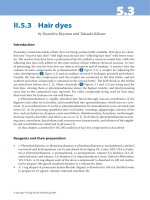
X-ray may be taken. Pacemakers have a logo, code or distinct radiographic “skel-
eton” that may be matched to a reference text (Fig. 11.1). If the manufacturer can
be identified, a call to the manufacturer’s patient registration department can pro-
vide the basic information needed. Table 11.2 provides phone numbers in the
United States for some of the pacemaker companies.
As with any medical problem, the history is usually the key to determining the
cause of a problem or at least to significantly narrowing the diagnostic options. If
the problem occurs shortly after implant then lead dislodgment, insufficiently
tightened set screws, or poor lead placement should be suspected as a cause rather
than battery depletion or lead fracture. Conversely, an older device is more likely
to be compromised by lead failure and battery depletion rather than lead
dislodgment.
The presence or absence of symptoms is very important. This will determine if
urgent action is required or if the luxury of a more leisurely approach to problem
solving is appropriate. The first step in a grossly symptomatic patient is to estab-
lish a stable cardiac rhythm. If the patient is severely bradycardic and the pace-
maker programmer is not available or programming changes to the device are
ineffective, temporary transvenous pacing should be established as soon as possible.
92 Handbook of Cardiac Pacing
11
Ta b le 11.1. Basic troubleshooting data requirements
Pacemaker model
Pacemaker serial number
Lead model(s)
Lead serial numbers(s)
Date of implant for each component
Current programming
Measured data
Lead impedance(s)
Battery voltage and / or impedance
Indication for pacing
Chest X-Ray (if needed or indicated)
Fig. 11.1. Radiographic logos can be used to identify a device quickly. Either a code that can be deci-
phered by using a book or calling a manufacturer, or a model number may be present. In this radio-
graph the model number 262-14 is clearly seen, instantly identifying the pacemaker.
If necessary, external pacing may be used until a more definitive solution is a-
vailable.
A tachycardia driven by the pacemaker presents a more difficult situation. In
most cases application of a magnet or a programming change will terminate the
rapid rhythm. In rare cases the pacemaker will not respond and urgent surgical
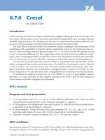
intervention may be required for “runaway pacemaker” (Fig. 11.2). This uncom-
mon malfunction is caused by a major component failure in the pacing circuit.
The vast majority of rapid pacing rates are caused by a DDD or VDD device tracking
93Evaluation of Pacemaker Malfunction
11
Ta b le 11.2. Phone numbers for pacemaker and ICD manufacturers
Biotronic 800-547-0394
Cardiac Control Systems (CCS) 800-227-7223
Cardiac Pacemakers, Inc (CPI) 800-227-3422
Cordis 800-777-2237
Ela 800-352-6466
In Control 425-861-9301
Medtronic 800-328-2518
Sulzer-Intermedics 888-432-7801
Pacesetter, St. Jude 800-777-2237
Te lectronics 800-777-2237
Ve ntritex 800-777-2237
Vitatron 800-848-2876
Fig. 11.2. Runaway pacemaker. This strip shows VVI pacing at 180 bpm (the runaway protect limit on this
device). The pacemaker was programmed to the DDD mode with an upper rate limit of 120 bpm. Thera-
peutic radiation delivered to the pacemaker in a pateint with breast cancer resulted in circuit failure and
rapid pacing. Even magnet application did not slow the pacing rate. The device was replaced emergently.
atrial fibrillation or flutter. The pacemaker will try to track the rapid atrial rate to
the upper rate limit of the pacemaker. Placing a magnet over the device will drop
the pacing rate to the magnet rate of the device until it can be programmed to a
nontracking mode such as DDI or VVI. Sensor-driven devices may cause rapid
pacing as well. In one case we found a patient who was experiencing a wide com-
plex tachycardia and a tonic-clonic seizure. The wide complex tachycardia was the
result of a vibration based sensor-driven pacemaker responding to the seizure.
Note that it is still quite possible for a patient with an intact AV node to have an
atrial arrhythmia with rapid ventricular response. Unfortunately the pacemaker
is of little help in this situation. Many times the patient and others expect that we
will be able to reduce the intrinsic heart rate by reprogramming of the device.
This is not true and represents a misunderstanding of the function of a pace-
maker.
After the condition of the patient is stabilized, the history obtained, and the
initial data concerning the device is obtained, the ECG is evaluated. An approach
to determining the general function of the pacing system is detailed in Table 11.3.
94 Handbook of Cardiac Pacing
11
Absence of a pacing output may be caused not only by output problems but
also by oversensing. An easy way to remember this is that “oversensing causes
underpacing, and undersensing causes overpacing.” If the pacemaker is sensing
an electrical event, the pacemaker will be inhibited. Often times this is a prema-
ture ectopic beat that may be isoelectric on a single monitor lead. For this reason
multi-lead recordings are needed to evaluate the system properly. Oversensing
can be diagnosed quickly by placing a magnet over the device. If pacing resumes
while the magnet is in place then oversensing is a problem. If there is no pacing
with the magnet on, then either the pacemaker is not putting out a pulse or the
pulse is not reaching the heart.
Once the nature of the problem is identified, consideration of the possible
causes is necessary so that appropriate corrective action may take place. It must
also be understood that a failing pacemaker may manifest any of the following
malfunctions due to the unpredictable nature of circuit failure or the effects of
low battery voltage on the circuit. Causes of true pacemaker failure are noted in
Tabl e 11.4.
N
ONCAPTURE
This potentially life threatening problem is identified by the presence of pace-
maker pulse artifact without capture (QRS or P wave) following the impulse
(Fig. 11.3). Causes of noncapture are listed in Table 11.5.
Corrective Action
Increase pacemaker output if possible. Where appropriate, revise or replace
lead or pacemaker, correct metabolic imbalances. For pseudo-noncapture adjust
the sensitivity to a more sensitive setting.
Ta b le 11.3. Approach to the ECG
1. Pacing
a. Spike present
1) Verify appropriate rate interval
2) Verify appropriate depolarization response
a) capture
b) pseudofusion
c) fusion
b. Spike absent
1) Apply magnet (magnet function must be enabled)
(Note: a ventricular pacemaker spike falling in the absolute refractory period of
the myocardium will NOT result in capture.)
2) Observe on 12 lead ECG for pace artifact and capture.
2. Sensing
a. Patient must have periods of nonpaced rhythm
b. Appropriate escape interval—Hysteresis
3. Compare function to known technical information, observing for end of service
indications and other variations.
95Evaluation of Pacemaker Malfunction
11
Ta b le 11.4. Causes of pacemaker failure
Battery depletion
Defibrillation near or over the device
Use of electrocautery near or on the device
Random component failure
Severe direct trauma to the device
Therapeutic radiation directed at or near the device
Known modes of failure for devices on recall or alert
Fig. 11.3a. Atrial noncapture. In this dual chamber device, atrial capture is lost as can be seen by the
absence of a P wave, and the sudden appearance of a wide complex QRS.
Fig. 11.3b. Ventricular noncapture. Paced output occurs without depolarizing the ventricle resulting in an
asystolic pause. This pacemaker was programmed to VVI at 70 bpm.
Ta b le 11.5. Common causes of noncapture
Exit block (high-capture threshold)
Inappropriate programming to a low output or pulse width
Lead dislodgment
Lead fracture
Lead insulation failure
Loose connection to pacemaker
Low battery output
Severe metabolic imbalance
Drug effect
“Pseudo-noncapture” (pacing during the refractory period due to undersensing of the
preceding complex)
96 Handbook of Cardiac Pacing
11
UNDERSENSING
Recognized by the presence of pulse artifact occurring after an intrinsic event
which occurs but does not reset the escape interval (Fig.11.4). This may or may
not capture depending on where in the cardiac cycle the pace output falls. Causes
of undersensing (thus “overpacing”) are listed in Table 11.6.
Corrective Action
Increase pacemaker sensitivity. Where appropriate, revise or replace the lead.
If the problem is very infrequent then careful observation may be acceptable.
OVERSENSING
Recognized by inappropriate inhibition of the pacemaker in a single chamber
system (Fig.11.5). This may be seen as total inhibition of output or as prolonga-
tion of the escape interval. Myopotentials cause a form of oversensing seen
Ta b le 11.6. Causes of undersensing
Poor lead position with poor R-wave or P-wave amplitude
Lead dislodgment
Lead fracture
Lead insulation failure
Severe metabolic disturbance
Defibrillation near pacemaker
Myocardial infarction of tissue near electrode
Ectopic beats of poor intracardiac amplitude
DVI-committed function
Safety pacing
Fig. 11.5. Myopotential inhibition. As the patient begins to use the arm on the same side of the pacemaker,
the electrical signals of the pectoralis are sensed and mistaken to be QRS signals. The device is inhibited
until the patient relaxes. Note the muscle artifact on the baseline of this rhythm strip.
Fig. 11.4. Undersensing. This pacemaker is not sensing any of the intrinsic complexes (pacing asynchro-
nously). The device is programmed to VVI at 45 bpm with a very low sensitivity setting. Note that the 3rd
paced output fails to capture as it occurs during the refractory period of the ventricle.
97Evaluation of Pacemaker Malfunction
11
Ta b le 11.7. Causes of oversensing
Myopotentials
Electromagnetic interference
T-wave sensing
Far-field R-wave sensing (atrial lead)
Lead insulation failure
Lead fracture
Loose fixation screw
Crosstalk
Fig. 11.6. Myopotential tracking. This pacemaker is tracking the patient’s sinus rhythm. As the patient
begins to use the arm on the same side of the pacemaker, the atrial channel of the pacemaker senses the
electrical impulses generated by the pectoralis muscle. The pacemaker “tracks” the myopotentials instead
of the P-waves resulting in loss of AV synchrony and rapid ventricular pacing. If the myopotentials inhibit
the ventricular channel, asystole may result.
predominantly in unipolar pacemakers. Inhibition is usually caused by sensing
noncardiac muscle activity. Myopotentials are typically caused by arm movements
or lifting for prepectoral implants, and by sitting up for abdominal implants. In-
hibition may also be caused by the ventricular lead sensing the T-wave. This “fools”
the device into believing a cardiac event has occurred. Output is therefore inhib-
ited as long as these signals continue. Dual chamber systems may exhibit tracking
of electrical signals such as myopotentials. This is caused by the same mechanisms
as is inhibition as just discussed (inhibition may occur in either the atrium, ven-
tricle or both with a dual chamber pacemaker). However, rapid pacing may be the
result of oversensing of electrical signals on the atrial channel that are not strong
enough to be sensed on (and thus inhibit) the ventricular channel. The atrial chan-
nel is usually set to a more sensitive value than the ventricular one. What happens
is that an AVI is started each time oversensing occurs triggering a ventricular out-
put at a rate up to the programmed URL. This is demonstrated by tracking of
myopotentials on a unipolar system as shown in Figure 11.6. Additional causes of
oversensing are listed in Table 11.7.
Corrective Action
Decrease the sensitivity of the device. For far-field or T-wave sensing, prolon-
gation of the refractory period will correct the problem. The sensing polarity may
98 Handbook of Cardiac Pacing
11
Fig. 11.7. Retrograde conduction. In this example the pacemaker is programmed to VVI. There is a retro-
gradely conducted and inverted P-wave in the T-wave. This can lead to pacemaker syndrome and pace-
maker mediated (endless loop) tachycardia.
be reprogrammed to bipolar if the option is available and the patient has a bipolar
lead. In some cases surgical intervention may be needed to repair the lead, replace
the lead, or change to a bipolar system. See the section on crosstalk below for
additional information.
D
IAPHRAGM PACING AND EXTRACARDIAC STIMULATION
This is relatively unusual but may be caused by either an atrial lead stimulating
the phrenic nerve or by direct stimulation of the diaphragm or chest wall muscle
by the ventricular lead. Extracardiac stimulation occurs due to poor lead place-
ment and/or high output setting of the pacemaker. Occasionally perforation by
the lead of the myocardium may cause this as well. Unipolar pacemakers and leads
with failed outer insulation may also cause local tissue stimulation.
Corrective Action
Decrease output if possible to do so and still maintain an adequate safety mar-
gin for capture. Revision of a culprit lead may be necessary.
PACEMAKER SYNDROME
This can occur in patients with sinus rhythm who receive VVI pacing systems
or in patients with dual chamber devices where the atrial lead does not properly
capture or sense. When the atrial contribution to ventricular filling is lost by pac-
ing the ventricle alone, the cardiac output drops and the patient feels fatigued and
uncomfortable whenever the pacemaker is pacing. They may have palpitations or
chest pulsations due to the “cannon A waves” caused by the atrium contracting
against the closed mitral and tricuspid valves. The classic patient to develop pace-
maker syndrome is one with retrograde AV node conduction. The latter occurs
when the ventricle is paced and contracts. The depolarization impulse travels in a
retrograde manner up the bundle of His through the AV node to the atrium. The
atrium then contracts against the mitral and tricuspid valves which are closed due
to the ventricular contraction. The late atrial contraction causes retrograde blood
flow in the venous system with “cannon A waves”, dyspnea, fatigue and even syn-
cope. Clues to this phenomenon can be seen on the surface ECG.
In many cases an inverted P-wave can be seen in the T-wave (Fig. 11.7). This
represents the retrograde conduction and the ineffective as well as detrimental
99Evaluation of Pacemaker Malfunction
11
atrial contraction. Patients without retrograde conduction may also have a form
of pacemaker syndrome due to loss of consistent atrioventricular synchrony. Ex-
acerbating factors predisposing a patient to this problem relate to loss of ventricu-
lar compliance. The latter is seen in patients with hypertension, ischemic disease,
hypertrophic disease and those who are elderly.
Corrective Action
For VVI devices, reduce the pacing rate or program hysteresis on to allow more
time in sinus rhythm. If this does not provide a satisfactory solution, then a change
to an atrial or dual chamber device is indicated. If the problem is due to a mal-
functioning atrial lead on a dual chamber system, then either reprogram to elimi-
nate the problem or correct the lead surgically.
DUAL CHAMBER PACING
Many pacing problems are shared between single and dual chamber systems.
However, there are a number of behaviors and malfunctions that are unique to
the dual chamber pacemakers.
P
ACEMAKER MEDIATED TACHYCARDIA (PMT)
PMT (also referred to as endless loop tachycardia or ELT) is an abnormal state
caused by the presence of an accessory pathway (the pacemaker). It is essentially
identical to the tachycardia seen in patients with Wolff-Parkinson-White syndrome.
PMT often begins with a premature ventricular beat that is either spontaneous or
pacemaker induced (Fig 11.8a). The electrical impulse travels retrogradely up the
bundle of His to the AV node and then to the atrium (Fig 11.8b). If this retrograde
P-wave occurs after PVARP has ended, it will be sensed by the pacemaker. This
will start an AV interval, after which the pacemaker will deliver an impulse into
the ventricle (Fig 11.8c). This starts the cycle over again. It will continue until one
of the following occurs: 1) the retrograde P-wave blocks at the AV node, 2) the
retrograde P-wave falls within PVARP, 3) a magnet is applied to the pacemaker
(disabling sensing) or 4) the device is reprogrammed to a longer PVARP. The pa-
tient may cause transient AV-block by using standard vagal maneuvers to block
the AV node terminating the tachycardia. Though not commonly used, adenosine
may be given IV to break the tachycardia. PMT may be initiated or restarted by
anything that causes a ventricular beat to occur before an atrial beat. This includes
a PVC, PJC, loss of atrial sensing or atrial capture, and myopotential tracking or
inhibition in the atrium.
PMT may be prevented by appropriate programming of the PVARP such that
any retrograde P-waves will fall within this interval and therefore not be sensed by
the atrial channel. Unfortunately, in patients with prolonged AV-nodal conduc-
tion, the long PVARP that is necessary to prevent PMT may severely limit the
100 Handbook of Cardiac Pacing
11
maximum tracking rate of the device due to the resulting long TARP. Some pace-
makers have special options to prevent PMT, allowing a shorter PVARP to be pro-
grammed. One option is the ability to use a short baseline PVARP that automati-
cally extends after any cycle following a sensed R-wave that is not preceded by a
Pwave (presumably a PVC). This event prolongs the PVARP for only one cycle
then reverts back to the shorter one. Another variation of this method is to turn
off atrial sensing completely for the cycle following a PVC. This is described as
DVI on PVC since there is no atrial sensing for the one cycle. It was once known as
DDX by one manufacturer. Finally, some devices provide an automatic termina-
tion algorithm if PMT is suspected. When the pacemaker is at its upper rate for a
specified number of beats the device may insert a single long PVARP. This action
will terminate the PMT if it is present.
Fig. 11.8. Pacemaker mediated tachycardia (PMT). A PVC occurs (A) causing the ventricle to contract.
The electrical impulse is conducted in a retrograde manner through the AV node (B) causing the atrium
to contract. The retrograde P wave is sensed by the pacemaker which then starts an AV interval. At the end
of the AV interval a pace stimulus is delivered to the ventricle (C) and the cycle continues.
101Evaluation of Pacemaker Malfunction
11
Fig. 11.9. Crosstalk. This pacemkaer is programmed to DDD at 80 bpm with an AVI of 200 ms. Note the
paced atrial events with no paced ventricular events and a shorter AA interval. The AEI begins shortly
after the atrial pace, advancing the next atrial output by the AVI. This results in a pacing rate above the
base rate. If there is no ventricular escape rhythm crosstalk may result in asystole.
CROSSTALK
This is a potentially dangerous or lethal problem in patients who are pace-
maker dependent. Crosstalk occurs when the ventricular sensing amplifier senses
the atrial pacing impulse and interprets the atrial pace as an intrinsic ventricular
beat. The ventricular output is then inhibited and, if the patient has no ventricu-
lar escape, asystole occurs (Fig.11.9). This is seen on the ECG strip as paced atrial
P-waves without a ventricular output. Typically the atrial pacing interval is equal
to the AEI. This is because the AVI is terminated by the ventricular sensing of the
atrial pacing pulse, resetting the pacemaker for the next cycle. However, in an
atrial based system the AVI will be allowed to complete before the next AEI starts
thus maintaining the programmed pacing rate. Crosstalk is most likely to occur
when the atrial output is set very high and the ventricular sensitivity is also set
very high.
The prevention of this problem is critical. Most modern pacemakers are very
resistant to crosstalk. This problem may be prevented by avoiding settings that
predispose the system to crosstalk, and by programming an appropriate blanking
period. Additional features may be present to prevent or reduce the effect of
crosstalk.
“Safety Pacing” (also known as “Ventricular Safety Standby” and “Non-
physiologic AV Delay”) allows a brief period of ventricular sensing during the
early postatrial output period. This interval that follows the blanking period is
known as the “crosstalk sensing window”. If an event is sensed in this period of
time a ventricular pace is committed at a short AV-delay (usually 100-120 msec).
This provides ventricular pacing support should crosstalk actually be present. The
ventricular pulse will not fall on the “vulnerable period” should a PVC or other
intrinsic atrial beat be present (Fig. 11.10). Please note that this feature does not
prevent crosstalk. It is meant only to prevent the result of crosstalk. If safety pac-
ing is present the cause should be identified and corrected as soon as possible.
102 Handbook of Cardiac Pacing
11
Fig. 11.10a. Safety pacing during crosstalk. This strip is from the same patient as described in Fig. 11.9,
however safety pacing is enabled. Instead of paced P waves with no ventricular output, the pacemaker
paces at the end of the crosstalk sensing period (see text). The ventricular pace occurs between 110 and
120 msec after the atrial output regardless of the programmed AVI. This feature guards against inappro-
priate inhibition of the ventricular output.
Fig. 11.10b. Safety pacing with PVC. In this example a PVC occurs during the crosstalk sensing period.
The pacemaker is not able to differentiate between crosstalk and an actual cardiac event during this pe-
riod. It therefore will deliver a safety pace (SP). The short AVI used in safety pacing insures that this pulse
falls into the refractory period of the ventricle and not onto the vulnerable area of the ST segment.
ACCUFIX/ENCOR LEADS
A unique design for preformed atrial J-leads from Cordis and Telectronics uses
a small piece of spring wire either under the insulation of the lead or within the
conductor coil(s) of the lead. The purpose of this spring wire is to assist in main-
taining the “J” shape of the lead. In a significant number of patients this spring
wire has been known to fracture. This can result in perforation of the insulation
by the spring wire (Fig. 11.11) with possible perforation of the atrium and even
aorta. Should this occur, acute pericardial tamponade could result with a subse-
quent cardiovascular emergency. Patients with these leads should be screened us-
ing cinefluoroscopy in four views to assess the integrity of the lead. If removal of
the lead is necesssary or desired, the patient should be referred to a center of
excellence.
Figure 11.12 shows a typical lead fracture. Most of these occur as shown in the
area just under the clavicle. This is caused by the additional stress placed on the
103Evaluation of Pacemaker Malfunction
11
Fig. 11.11. Teletronics
Accufix lead radio-
graph showing frac-
ture and protrusion of
the J-retention wire.
Fig. 11.12. Radiograph of a fractured lead. This lead has a failure of the outer coil as it passes under the
clavicle. This is the most common site of lead fracture.