HANDBOOK OF CARDIAC PACING – PART 8 pdf
Bạn đang xem bản rút gọn của tài liệu. Xem và tải ngay bản đầy đủ của tài liệu tại đây (452.94 KB, 16 trang )
104 Handbook of Cardiac Pacing
11
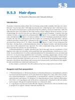
Fig. 11.13. Normal appearing lead placement
Radiograph. a. PA radiograph taken with the
patient upright with a full inspiration. This is a
dual chamber pacemaker with normal appear-
ing lead placement. The atrial lead is in the right
atrial appendage and the ventricular lead in the
right ventricular apex. The leads have adequate
slack, and there are no defects or kinks noted.
Fig. 11.13b. Lateral radiograph of the same pa-
tient. Note the anterior position of both leads.
leads as they pass through the soft tissue structures (ligament and muscle) before
entering the subclavian vein. Additional stress may be cased by compression of
the leads from the first rib and the clavicle when the leads are implanted in a
medial postion relative to the first rib. Finally, Figure 11.13 shows a normal ap-
pearing PA and lateral chest x-ray. In this example the leads are properly placed
into the atrium and ventricle with appropriate amounts of slack in each chamber.
105NBD Code for Implantable Cardioverter Defibrillators
12
Handbook of Cardiac Pacing, by Charles J. Love. © 1998 Landes Bioscience
NBD Code for Implantable
Cardioverter Defibrillators
The implantable cardioverter defibrillator (ICD) has revolutionized the treat-
ment of lethal tachyarrhythmias. New devices are being designed for the treat-
ment of atrial fibrillation as well. As these devices are quite a bit different in func-
tion and have different features than their pacemaker cousins, they need their
own descriptive codes. As described in chapter 1, the North American Society of
Pacing and Electrophysiology and the British Pacing and Electophysiology Group
(NASPE and BPEG or the NBG) developed a system known as the NBG Code to
describe the functionality of pacemakers. The fifth position of the code is meant
to describe the antitachycardia features of a device. In 1993, the NBG developed
another code that was directed at devices whose primary function was that of
treating tachycardia rather than bradycardia. This code is very similar to the NBG
Code and is known as the NBD Code (NASPE-BPEG Defibrillator Code).
The positions of the NBD code differ in meaning from those of the NBG code,
but many of the letters used have the same meanings (Table 12.1). As with the
NBG code the first position of the NBD code represents the chamber used for the
primary purpose of the device; the delivery of a shock. The chamber(s) shocked
are V for Ventricle, A for Atrium, D for Dual and O for no chamber shocked. The
second methodology for tachycardia termination is antitachycardia pacing (ATP).
The chambers with this type of therapy activated are described by the second
position in the code. The letters V, A, D and O used in this position are identical to
and have the same meaning as the letters of the first position. The third position
describes the method of tachycardia detection. The method for detecting
arrhythmias in most antitachycardia devices is the rate and or morphology as
seen from the intracardiac electrogram. Another method of detecting an arrhyth-
mia is to monitor a hemodynamic parameter for evidence of compromise or col-
lapse. Therefore E is used to designate Electrogram detection and H is used for
Hemodynamic detection. If you remember these first three positions then the last
one is easy as it describes the bradycardia pacing capabilities of the defibrillator.
This position uses the same letters with the same meaning as the first position of
both the NBG and NBD code: V, A, D and O. Some defibrillators have full dual
chamber and sensor-driven pacing functions. Complex bradycardia pacing func-
tionality of a defibrillator may be described by adding the first three or four letters
of the NBG code after the first three letters of the NBD code. A hyphen is used to
separate the two codes for clarity. An example of an ICD that shocks the ventricle
with no antitachycardia pacing, uses electrograms for detection and has ventricu-
lar bradycardia pacing capability would be described as a VOE-VVI defibrillator.
106 Handbook of Cardiac Pacing
12
The use of two different codes may be a bit confusing. To avoid misunder-
standing the code should be followed by the type of device. Examples of this would
be “VVEO defibrillator” or “VVIR pacemaker.” This implies the NBD and NBG
codes respectively. The question as to which code to use if a device has both brady-
cardia and tachycardia features should be based on the primary design function
of the device. An ICD with backup VVI pacing should be described using the
NBD format while a pacemaker with antitachycardia pacing capability is best de-
scribed using the NBG format.
Ta b le 12.1. NBD codes (for implantable defibrillators).
1st position indicates the chamber shocked:
V = ventricle
A = atrium
D = dual
O = no shock therapy
2nd position indicates the chamber for antitachycardia pacing:
V = ventricle
A = atrium
D = dual
O = no antitachycardia pacing
3rd position indicates the method of tachycardia detection:
E = electrogram
H = hemodynamic
4th position indicates chambers for bradycardia pacing*
V = ventricle
A = atrium
D = dual
O = no bradycardia pacing.
*Alternatively the three or four letter NBG pacing code may be used following the first
three letters of the NBD code (e.g., VVE-VVIR indicating ventricular shock, ventricular
ATP, electrogram detection and VVIR pacing capability).
107Basic Concepts of Implantable Cardioverter Defibrillators
13
Handbook of Cardiac Pacing, by Charles J. Love. © 1998 Landes Bioscience
Basic Concepts of Implantable
Cardioverter Defibrillators
Introduction 107
Basic Concepts 110
Capacitors 110
Lead 110
Sensing 112
Defibrillation Waveform 115
Defibrillation Threshold 116
Anti-Tachycardia Pacing (ATP) 116
Committed vs. Noncommitted 117
Bradycardia Backup and Postshock Pacing 118
Counters and Electrograms 118
Magnet Response of the ICD 121
Recommended Replacement Time 121
INTRODUCTION
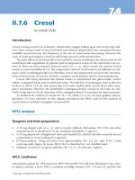
Though an implantable cardioverter defibrillator (ICD) may look like a large
pacemaker and have pacing ability, it is actually quite a different device (Fig. 13.1).
The differences are reflected in all aspects of the system from the lead to the power
source.
The earliest ICDs were very effective but very primitive relative to today’s ICDs
and even relative to the pacemakers of the time. The first ICDs were implanted in
humans in 1980 and approved for general use by the United States Food and Drug
Administration in 1985. These units were similar to the first pacemakers implanted
in 1958 as they were not programmable. The device was ordered with a specific
detection rate from the factory and no changes were possible other than turning it
on or off. This presented significant problems since the patient’s arrhythmia sub-
strate is subject to change. Ischemic events, progression of other underlying car-
diac disease, and changes in medical therapy may affect tachycardia rates. A com-
mon situation would be seen if a new drug such as amiodarone was started on a
patient. If the ventricular tachycardia rate were to be slowed below the detection
rate of the ICD then the cardioversion would not be delivered as it should have
been. The options would be to discontinue the medication or reoperate to replace
the ICD using one with a lower detection rate. The cost of an ICD and lead system
is in the range of $15,000 to 29,000, and until the recent past required a major
surgical procedure. Replacement is not an option that would be done without a
great deal of consideration. ICDs that have programmable detection rates have
108 Handbook of Cardiac Pacing
13
been available for general use since 1988. This allows the tailoring of therapy as
the patient’s needs change.
ICDs subsequently were developed that had several tiers of therapy. Instead of
a single detection rate, several detection zones may be set up with different therapy
being delivered to the different types of tachycardia. A patient with a history of
spontaneous ventricular fibrillation would typically be set to a single zone for
detection, and a series of shocks for therapy. Another patient with a history of
slow ventricular tachycardia might be set with two zones of therapy. The first zone
detects the slow ventricular tachycardia and treats the tachycardia with a series of
overdrive pacing pulses. If these are not effective a low energy cardioversion is
Fig. 13.1. Picture of old and new ICDs front (a) and
profile (b). Note the marked decrease in size that has
occurred over the past 5 years.
Fig. 13.1a.
Fig. 13.1b.
109Basic Concepts of Implantable Cardioverter Defibrillators
13
then performed, and if necessary a high energy shock would be delivered. A sec-
ond zone to detect faster rates would be entered if the patient developed sponta-
neous ventricular fibrillation, rapid ventricular tachycardia, or if in attempting to
pace the patient out of the tachycardia the arrhythmia is accelerated. The device
would then apply more aggressive therapy and shock the patient immediately.
Devices now allow up to four different rate zones for detection. Within each de-
tection zone a series of different therapies are available. There are literally thou-
sands of detection and therapy permutations that may be used. It should be clear
that these devices are very complex and that there may be life threatening conse-
quences if programmed improperly. Only persons who are thoroughly familiar
with the particular device, the patient’s needs, and electrophysiology should pre-
scribe and perform programming changes.
The first ICDs were implanted by opening the chest and placing wire mesh
patches directly on the heart or pericardium in order to deliver a high energy
shock. Epicardial leads were also placed to sense the heart rate. Multiple approaches
to placing the leads on the heart were developed. These included median sterno-
tomy, lateral thoracotomy, subcostal, subxiphod and combinations of these ap-
proaches with a transvenous endocardial lead for sensing and pacing the heart.
Eventually nonthoracotomy transvenous systems were devised to eliminate the
need for opening the chest. These required placing multiple leads in the superior
vena cava, subclavian vein, innominate vein and/or the coronary sinus. In many
cases a subcutaneous patch or wire array is needed to provide effective therapy.
The most advanced devices now combine the ease of using a single lead that com-
bines pacing, sensing and one or more high energy coils for shocking the heart
with an “active” or “hot” ICD case that acts as another shocking surface (Fig 13.2).
This advanced hardware in combination with more efficient shock waveforms
Fig. 13.2.a. Active can to coil design is currently the most popular. It is simple in design, easy to implant,
and highly effective in converting ventricular arrhythmias. It uses a single coil in the heart (though some
systems use an extra coil in the superior vena cava), and the ICD itself is electrically active behaving as the
anode or cathode for shock. b. Inactive can and leads is an older design, but still occasionally used, espe-
cially for replacement of an existing system of similar design. The ICD itself is not part of the shock
circuit. There must therefore be at least 2 coils in the venous system, or 1 coil in the heart and a subcuta-
neous electrode. c. Epicardial patches and leads are rarely used due to the higher morbidity of the opera-
tion, and the high degree of efficacy of the transvenous systems.
110 Handbook of Cardiac Pacing
13
has allowed ICD implant to be performed in 30 minutes under local anesthesia as
an ambulatory procedure.
BASIC CONCEPTS
Externally the ICD components are the same as those of a pacemaker. Inter-
nally there are two major differences.
Battery: The battery of an ICD differs from the chemistry used for pacemak-
ers. The battery of a pacemaker is designed to deliver small amounts of current
continuously over many years. The battery in an ICD must deliver large amounts
of current in a very short period of time. The chemistry most commonly used is
silver vanadium pentoxide. Though the shelf life of this chemistry is not as long as
lithium iodine, it has the characteristics needed to provide the current quickly to
the capacitors without suffering internal damage. In some cases two batteries may
be used in series to improve the charging rate of the capacitors. Newer ICDs are
being designed with two types of batteries, one to run the circuitry and pacing
functions, and one to charge the capacitors.
CAPACITORS
These large and bulky components are necessary to change the 3 volts sup-
plied by the battery into the 750 volt shock required to defibrillate a heart. Until
very recently the basic design of the capacitors had been large and round. This
makes them very difficult to place in a space efficient manner in the case. Newer
designs using “flat” capacitors and ceramic designs have led to a dramatic de-
crease in size and much more flexibility in shape. The result is a much smaller case
for the components. Capacitors must be charged fully at regular intervals to main-
tain their ability to charge to full capacity. This is known as “reforming” the ca-
pacitor. Earlier devices required that the patient come to the physician’s office to
charge up the capacitors (without delivering the current to the patient) once ev-
ery several months. Modern ICDs have an internal clock and calendar that allow
the performance of this maintenance function automatically if the patient has not
required a shock in several months.
LEAD
The function of the lead system for an ICD includes pacing and sensing the
heart as in a standard pacing system. It must also have the ability to deliver ap-
proximately 750 volts. In the early designs, different lead systems were used to
handle the different functions. One set of leads was present for the sensing and
pacing needs and a second set was present for the high energy needs. The latter are
shown in Figure 13.3. These would be applied directly to the heart and were placed
111Basic Concepts of Implantable Cardioverter Defibrillators
13
Fig. 13.3d. Transvenous electrodes have virtually replaced all epicardial
lead systems for ICDs. They are placed in a manner similar to pacing
leads.
Fig. 13.3a. Originally, large patches such as this once were placed directly
on the surface of the heart. Later, they were also used subcutaneously to
provide additional surface area for transvenously placed systems.
Fig. 13.3b (above). As a variant on the patch, a
subcutaneous array was developed. These coils
were inserted into the tissues between the ribs.
Fig. 13.3c (above). Screw on electrodes were used to
pace and sense the heart. These are designed to be
placed on the epicardial surface of the heart and were
used in most of the implants before the transvenous
systems were introduced.
112 Handbook of Cardiac Pacing
13
within the central venous circulation, in the great cardiac vein, or in the subcuta-
neous tissue. The sensing leads were epicardial screw-in or in some cases were
long pacing leads placed transvenously. As with pacing leads, conductor fractures
and insulation failures are not uncommon.
SENSING
Sensing the heart rate is very important as this is the primary method for the
ICD to determine if a tachycardia is present or not. There are two configurations
that are true bipolar and integrated bipolar. True bipolar sensing uses the same
methodology as in pacing. A lead with the cathode and anode are present within
the ventricle (Fig 13.4a). These are dedicated to pacing and sensing functions and
do not form any part of the shocking high voltage circuit. The second configura-
tion uses a cathode at the tip; however the anode is the distal shocking coil
(Fig 13.4b). This configuration is referred to as “integrated bipolar,” allowing the
lead to be of more simple design. However, since the shock coil doubles as the
sensing coil there may be some difficulty sensing immediately after a shock is
delivered. This rapidly resolves and normal sensing resumes. Some devices use
true bipolar sensing and integrated bipolar pacing to overcome this limitation.
Due to the possible extreme differences in intracardiac electrograms between
normal beats, premature ventricular beats and ventricular fibrillation, the stan-
dard sensing methods used in pacing do not work well in ICDs. The fixed sensitiv-
ity level is not able to adapt to these wide swings in electrogram size. Most ICDs
use some variation of automatic gain control. After each sensed event the sensitiv-
ity is decreased, after which the device becomes increasingly more sensitive. This
helps to prevent oversensing of noncardiac events and the evoked T-wave. The
longer the device goes without sensing an event, the more sensitive it becomes.
This function provides the ability to detect if the patient has gone into a fine ven-
tricular fibrillation that might otherwise be missed if the sensitivity was not so
high.
Fig 13.4a. True bipolar sensing occurs
between a cathode and anode sepa-
rate from the defibirillation coils. b.
Integrated bipolar sensing uses a
cathode on the lead with one of the
defibrilation coils as the sensing an-
ode. Sensing may not be quite as reli-
able compared with the true bipolar
configuration.
a
b
113Basic Concepts of Implantable Cardioverter Defibrillators
13
DETECTION
The most straightforward method of determining if an arrhythmia is present
is to use a simple rate criteria. This is very sensitive, but lacks specificity. In other
words, it will sense virtually all life threatening arrhythmias but may also detect
sinus tachycardia or atrial fibrillation with a rapid ventricular response. In order
to improve the specificity of arrhythmia, additional detection parameters may be
used. These are listed in Table 13.1. It must be remembered that as with any test,
increasing the specificity means decreasing the sensitivity. I always say that it is
better to have an angry patient calling me due to an unnecessary shock rather
than not to have a patient alive due to failure of the algorithm to detect a lethal
arrhythmia. For this reason, the additional detection criteria are available to modify
the lower ventricular tachycardia zones and NOT the ventricular fibrillation zone.
The rate stability criteria is useful when a patient has atrial fibrillation with a
rapid ventricular response at times. If the ventricular tachycardia detection rate
and the ventricular rate when the patient is in atrial fibrillation overlap, then the
patient could get an unnecessary shock or series of shocks. Ventricular tachycar-
dia tends to be very regular beat to beat while the ventricular response to atrial
fibrillation tends to be very irregular. The rate stability criteria allows the pro-
gramming of a beat to beat variability limit (Fig 13.5). If the rhythm varies more
than this amount, it is classified as not being ventricular tachycardia and therapy
is withheld. The shortcomings of this methodology would be the presence of a
Ta b le 13.1. Detection criteria
Rate only
Rate stability
Sudden rate onset
Sustained high rate
Morphology
Atrial rhythm discrimination
Fig. 13.5. Rate stability may be used in addi-
tion to the ventricular rate as a secondary fac-
tor to determine the type of arrhythmia that
is present. While ventricular tachycardia tends
to be quite regular, fast ventricular rates caused
by atrial fibrillation with a rapid ventricular
response tend to be irregular. This diagram
shows a situation where the ventricular tachy-
cardia detection zone is set between 500 ms
and 350 ms, and the ventricular fibrillation
zone is below 350 ms. Though the heart rate
is in the VT zone, it is quite irregular, and thus
may be due to atrial fibrillation. The device
can be programmed to not deliver pace or
shock therapy in this situation.
114 Handbook of Cardiac Pacing
13
polymorphic ventricular tachycardia which would not be regular like monomor-
phic ventricular tachycardia. The polymorphic types tend to be faster in rate and
thus are less likely to overlap with the rates as seen in atrial fibrillation.
Another type of problem patient is one who is physically active and has a slow
ventricular tachycardia. In this case the sinus rates may overlap with the slow ven-
tricular tachycardia detection zone. In order to avoid shocking the patient when
the rate enters the detection zone due to normal activity, a sudden onset criteria
may be used. Sinus tachycardia tends to enter the detection zone in a gradual
manner with the heart rate slowly accelerating into the detection zone. Ventricu-
lar tachycardia tends to enter the detection zone rapidly, often after a premature
ventricular beat. The sudden onset criteria requires that if the interval between
the beat just before entry into the detection zone and the beat that is in the detec-
tion zone be longer than a specified period of time (Fig 13.6).
Since it is possible for ventricular tachycardia to occur and be missed due to
the use of the algorithms, another criteria may be activated to act as a backup
system. This is known as “sustained high rate,” “extended high rate” and “sus-
tained rate duration.” They are all basically the same, though each manufacturer
calls it by a different name. The purpose of this feature is to activate the therapy if
the rate stays in the detection zone for a prolonged period of time. Since it is
possible for a patient to enter the tachycardia zone slowly by exercising and then
develop ventricular tachycardia or for a patient to have a ventricular tachycardia
with an irregular rate, this feature acts as a “safety net”. It works by delivering
therapy if it had been withheld after a specified period of time or number of beats.
Fig. 13.6. Sudden onset of a fast rate may
be used to differentiate VT from sinus
tachycardia. VT tends to start with a
PVC and thus an abrupt change in cycle
length is noted (13.6a). Sinus tachycar-
dia tends to shorten the cycle length
gradually (13.6b). The tachycardia
shown in (a) will be treated while the
one in (b) will not be treated.
a
b
115Basic Concepts of Implantable Cardioverter Defibrillators
13
When a clinician attempts to determine whether a rhythm is ventricular ta-
chycardia or supraventricular tachycardia the width of the QRS if often quite help-
ful. Wide complex beats are most often ventricular and narrow complex beats are
usually supraventricular in origin. The ICD may use a morphology criteria to
determine whether a beat is wide or narrow. This differentiation may not work in
patients with underlying bundle branch block, rate dependent bundle branch block
or narrow morphology ventricular tachycardia. It does work in other patients and
may be used alone or with one of the other criteria in addition to the detection
rate.
The newest discrimination method to be introduced is the use of the intracar-
diac atrial signal as compared with the ventricular signal. The presence of atrio-
ventricular dissociation is diagnostic of a primary ventricular rhythm. Using this
technique a relatively slow ventricular rate that is present with an even slower
atrial rate can be assumed to be ventricular tachycardia as opposed to sinus tachy-
cardia. In addition, the atrial lead may be able to detect a rapid atrial rate to deter-
mine that the fast irregular ventricular rate is more likely to be due to atrial fibril-
lation with a rapid ventricular response. Obviously one must be very cautious
when making these determinations.
DEFIBRILLATION WAVEFORM
Just as with pacemaker pulses, the defibrillation pulse has both an amplitude
and a duration. The initial type of shock waveform was the monophasic trun-
cated exponential shape (Fig 13.7a). This delivered the energy in one direction.
Though this was effective in many patients it was not always successful. It was
even less effective when being used with the nonthoracotomy configurations. The
newer devices virtually all use a biphasic waveform (Fig 13.7b). During the deliv-
ery of energy with a biphasic pulse the initial direction of the current is reversed.
Fig. 13.7a. This is a diagram of a truncated ex-
ponential monophasic waveform. This was the
standard waveform of the early ICDs, and is
still used in virtually all external defibrillators.
b. The biphasic waveform as shown has been
found to be significanly more effective than the
monophasic version for converting fibrillating
heart rhythms to normal in most patients. It
has allowed the devices to be smaller due to
the lower DFTs achieved.
a
b
116 Handbook of Cardiac Pacing
13
This has been found to be an excellent method of defibrillation, and for the ma-
jority of patients results in a significantly lower amount of energy required to
restore the normal heart rhythm. Not only is polarity of the pulse important, but
the duration of the pulse (if monophasic) or duration of each segment of the
pulse (if biphasic) is critical. Pulses that are too short or too long will not be effective.
Pulses that spend too much time in one phase versus the other phase will likewise
be less effective.
DEFIBRILLATION THRESHOLD
Unlike pacing where the threshold is a fairly reproducible point on a strength
duration curve, the defibrillation threshold in a given patient with a given system
is a probability. A probability curve as shown in Figure 13.8 can theoretically be
produced for each patient. Unfortunately, given the method of device implant
this is rarely done. Typically two successful defibrillations at a single energy level
are used to confirm that the device will work. Some implantors will do repeated
testing until the lowest energy level that still defibrillates is found. Though this
seems much like pacemaker threshold testing, it is not. Without extensive and
repeated testing, the shape and position of the defibrillation threshold probability
curve will not be known. For practical purposes, the two shock method gives a
relatively high probability of being above the 90% confidence level for conversion
of ventricular fibrillation at a given energy level.
ANTI-TACHYCARDIA PACING (ATP)
ATP Is a very useful method to terminate monomorphic ventricular tachycar-
dia. It is most commonly used for slow tachycardias and those for which the pa-
tient is hemodynamically stable. The principle behind ATP is to entrain the tachy-
cardia by pacing at a rate faster than the tachycardia. This can allow the electrical
circuit within the myocardium that is perpetuating the rhythm to fatigue or block.
In either case the tachycardia terminates (Fig. 13.9). Patients find this method of
Fig. 13.8. DFT Probability curve. Defibril-
lation is not an absolute occurrence. At
high energy levels there is still the possi-
bility that the delivered energy may not
restore normal rhythm. Conversely, at low
energy levels there ay still be a small chance
that defibrillation will occur. To insure that
a single defibrillation was not a lucky con-
version in the low probability zone, several
tests of the system need to be performed
in order to verify that the subsequent prob-
ability of rescue is high.
117Basic Concepts of Implantable Cardioverter Defibrillators
13
arrhythmia termination far more preferable than receiving a shock. The most com-
mon way of delivering the ATP is by the device measuring the cycle length of the
tachycardia. It then will deliver a short burst of pacing pulses that begin at some
percentage (e.g., 87%) of the tachycardia cycle length. The pace pulses may all be
at one cycle length, or there may be a progressive shortening between each pulse.
The latter is known as RAMP pacing and is more effective than the fixed interval
burst type. One concern that is present when using ATP is the possibility of accel-
erating the tachycardia or fibrillating the heart. Should either one of these happen
the next level of therapy is available to deliver a cardioversion or defibrillation.
ATP is rarely programmed on as a sole therapy without shock therapy as a backup.
Another issue that must be considered is that ATP may cause a substantial delay in
the delivery of definitive therapy. This is usually not a problem except in patients
with ischemic cardiac disease. These patients may become severely ischemic dur-
ing long courses of ineffective ATP and be less likely to be successfully defibril-
lated if not done so quickly. Thus, ATP is indicated in patients with hemodynami-
cally stable ventricular tachycardia that has demonstrated termination with over-
drive pacing. It should be avoided in those patients where acceleration of the
tachycardia or induction of fibrillation has been shown to occur. It should not be
used in patients with hemodynamically unstable rhythms.
COMMITTED VS. NONCOMMITTED
Once the ICD has detected a rhythm for which it is to deliver a shock there are
two possible courses of action. The first is to simply charge to the programmed
output and deliver the shock. This is referred to as a committed shock as once
detection occurs the device is committed to deliver therapy. The second possibil-
ity is for the device to recheck or take a second look at the rhythm either while it is
charging or just before it delivers the shock. This is referred to as noncommitted
Fig. 13.9. ATP success. This patient went into ventricular tachycardia at a cycle length of 400-410 ms. The
ICD delivers 8 paced pulses at 370 ms which terminates the arrhythmia. The top trace is a far field electro-
gram recording from the shock electrode and defibrillator case, bottom trace shows the events as noted
and telemetered by the defibrillator (TS=tachycardia sense, TD=tachycardia detected, TP=anti-tachycar-
dia pacing, VP=ventricular pace, VS=ventricular sense). The numbers are the intervals measured between
events.
118 Handbook of Cardiac Pacing
13
since the ICD can “change it’s mind.” The advantage to a noncommitted device is
that if the tachycardia turns out to be a nonsustained event the ICD will not de-
liver an unnecessary shock. However, we are again faced with improving the speci-
ficity at the expense of sensitivity. In withholding the shock it is possible that due
to low amplitude fibrillation waves or polymorphic tachycardia that the ICD might
miss detecting the tachycardia on the second look. Most devices allow for the first
shock to be programmed as committed or noncommitted with the remainder of
the shocks being committed. The choice of which way to set the device is left to
the physician. Patients with a history of nonsustained ventricular tachycardia or
atrial fibrillation with periods of rapid response will typically have the
noncommitted shock feature on. Those with paroxysmal ventricular fibrillation
will often have it set to committed to insure that a shock is not delayed.
BRADYCARDIA BACKUP AND POSTSHOCK PACING
Virtually all ICDs being implanted have the ability to pace the ventricle as a
VVI pacemaker would. They may have a single pacing rate, a hysteresis rate and/
or a postshock pacing rate. The ability to pace VVI may be present even if ATP is
not available. Though pacing is available it is not routinely used as the primary
source of rate support for patients who require a pacemaker as well as an ICD.
This is due to the significant impact that sustained pacing can have on device
longevity. It may reduce the expected life of the ICD by up to 50% making it a very
expensive pacemaker. If pacing is going to be needed on a regular basis then a
separate dedicated pacemaker is frequently used. Some ICDs have two levels of
pacing output. One is used for routine bradycardia pacing and the other for ATP
and postshock pacing. The postshock and ATP outputs are typically set higher
due to the possibility of higher thresholds when the patient may be hypoxemic,
acidemic and ischemic. The postshock settings are typically used for several min-
utes before the standard settings are restored. Some ICDs also allow the program-
ming of a postshock pause before pacing starts and for a separate postshock pac-
ing rate. ICDs with full DDD capability are now available. DDDR capability will
be introduced in the near future as well.
COUNTERS AND ELECTROGRAMS
The most vital function that the device can serve other that rescuing the pa-
tient from a cardiac arrest is to assist the clinician in determining the etiology of
the event to which the device responded. Early ICDs had a simple counter that
indicated the number of device charges and discharges. This was only useful to
determine if a shock had occurred. There were no data recorded regarding the
rate of the arrhythmia, the date or time of occurrence, or the morphology of the
119Basic Concepts of Implantable Cardioverter Defibrillators
13
Fig. 13.10. The data log is a key element of the ICD evaluation. It details the date and time of each event
that met the detection criteria of the ICD, and the action taken by the device.
QRS at the time. The first improvement was the addition of a data logging system
that detailed the date and time of the arrhythmia and even of nonsustained events.
This was combined with a memory that would show the cycle lengths of the rhythm
(Fig 13.10). By reviewing this information, decisions regarding the type of ar-
rhythmia could be inferred. Regular intervals were consistent with monomorphic
ventricular tachycardia, while irregular intervals were assumed to be polymor-
phic ventricular tachycardia, atrial fibrillation with a rapid ventricular response,
or with ventricular fibrillation if the intervals were short enough. If the intervals
were excessively short, one would consider electromagnetic interference or a lead
failure that generated false signals (fractures and insulation failures can cause this).
ICDs are now capable of recording the intracardiac electrogram or a “far field”
electrogram during tachycardia detection and therapy. The “far field” electrogram
is recorded from electrodes that are not those typically used for sensing. This is
done by using the two shocking surfaces or a combination of shocking surface
and intracardiac electrode (the typical sensing electrode). The difference between
the near field and far field signals is shown in Figure 13.11. Note that the appear-
ance of the QRS and even the P-wave of the far field electrogram and the similar-
ity of this complex to that of a surface ECG recording. This is very useful to see
what the atrial activity is during the arrhythmia. Most devices do not begin to
record electrograms until tachycardia is detected. Some devices have a function
available similar to the looping memory event recorders. These ICDs are con-
stantly recording the electrograms and are able to freeze this information in
memory when a tachycardia starts. This not only gives a picture of the arrhyth-
mia, but also creates a record of the initiation of the event. Information of this
type is very valuable to the clinician but very expensive in terms of battery drain.
This feature is usually turned off unless there is a need to use it for diagnostic
purposes.