IP-Based Next-Generation Wireless Networks phần 7 doc
Bạn đang xem bản rút gọn của tài liệu. Xem và tải ngay bản đầy đủ của tài liệu tại đây (925.04 KB, 44 trang )
receives from the PS CN domain the user data destined to the mobile and then
distributes the data inside the RAN to the mobile.
In order for a mobile to exchange signaling messages with the PS CN (e.g., to set
up and manage the traffic bearers, to perform location update), a dedicated logical
signaling connection needs to be established between the mobile and the SGSN.
Recall that this signaling connection consists of a signaling Radio Bearer and an I
u
Signaling Bearer.
A mobile does not have to maintain all the traffic bearers in the RAN or the CN if
it does not expect to send or receive user data soon. The mobile does not even need
to maintain its dedicated signaling connection to the SGSN at all times. Releasing
the radio resources that a mobile is unlikely to need soon allows these radio
resources to be used by other mobiles and helps conserve the scarce power resources
on the mobile.
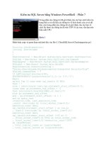
Which network connections (bearers) that make up the host-specific route
between a mobile and its serving GGSN need to be changed when the mobile moves
around depend on the scope of mobility. Figure 4.42 illustrates the different scopes
of mobility and which parts of the host-specific route betwee n a mobile and its
serving GGSN may be affected in each mobility scope.
. Inter-Node B Handoff: Handoff from one Node B (called the source Node B)
to another Node B (called the target Node B) requires that the mobile’s Radio
Bearers to be changed from the source Node B to the target Node B.
. Inter-RNC Handoff: With an inter-RNC handof f, a mobile moves its radio
bearers from one RNC (called the source RNC) to another RNC (called the
Fig. 4.42 Scope of mobility in 3GPP packet-switched domain
240 MOBILITY MANAGEMENT
target RNC). Therefore, if the target RNC also becomes the mobile’s serving
RNC after the handoff (e.g., in a hard inter-RNC handoff), the mobile’s I
u
Bearers also need to be changed, in addition to the changes of the Radio
Bearers.
. Inter-SGSN Handoff: With an inter-SGSN handoff, a mobile moves from one
SGSN (called the source SGSN) to another SGSN (called the target SGSN) as
a result of the handoff. Inter-SGSN handoff requires that the mobile’s PDP
context be updated and a new CN Bearer be established, in additi on to the
changes in the I
u
Bearers and the Radio Bearers.
. Inter-GGSN Handoff: With an inter-GGSN handoff, a new GGSN becomes a
mobile’s serving GGSN as a result of the handoff. This requires the mobile’s
new serving GGSN to create a PDP context for the mobile. It also requires a
CN Be arer to be established between the mobile’s new serving GGSN and the
mobile’s new serving SGSN. In addition, the mobile’s Radio Bearers and I
u
Bearers will need to be changed.
In the rest of this section, we will focus on the following key aspects of mobility
management for 3GPP packet-switched services:
. Packet Mobility Management (PMM) contexts and states: A mobile’s PMM
context is a set of information used by the network to track the mobile’s
location. The state of a mobile’s PMM context determines which networ k
connections (bearers) between the mobile and the SGSN should be maintained
for the mobile and how the network tracks the mobile’s location. PMM states
are described in Section 4.3.1.
. Location management and its interactions with the management of the host-
specific route between a mobile and its serving GGSN: Section 4.3.2
. Changes of the I
u
Bearers: When a mobile moves around, its serving RNC may
need to change from one RNC to another. As a result, the mobile’s I
u
Bearers
need to be changed. The process for relocating the RNC side of the endpoint of
an I
u
bearer from one RNC to another, i.e., the Serving RNS Relocation
Procedure, will be discussed in Section 4.3.4.
. Handoffs: Intra-RNC handoffs are managed by protocols and procedures
completely inside each specific RAN and therefore will not be discussed
further in this section. Inter-RNC handoffs for packet-switched services
require the support of PS domain protocols and procedures and will therefore
be discussed in Section 4.3.5.
4.3.1 Packet Mobility Management (PMM) Context and States
A mobile’s PMM context is a set of information used by the network to track the
mobile’s location. The state of a mobile’s PMM context determines which network
connections (bearers) between the mobile and the SGSN should be maintained for
the mobile and how the mobile’s location should be tracked by the network.
4.3 MOBILITY MANAGEMENT IN 3GPP PACKET NETWORKS 241
In the 3GPP PS domain, the SGSNs are responsible for tracking the locations of
mobiles that are using PS services. Therefore, the SGSNs need to maintain the PMM
contexts of the mobiles. Each mobile also needs to maintain a PMM context in order
to collaborate with the network for location tracking. The GGSNs, on the other hand,
are not directly involved in location tracking. Therefore, a GGSN does not need to
be aware of any mobile’s PMM context or PMM state.
A PMM context on a mobile or on an SGSN can be in o ne of the following states
(for UMTS) [10]:
. PMM-DETACHED State: In this state, there is no communication between the
mobile and the SGSN. The mobile and the SGSN do not have valid location or
routing information for the mobile. The mobile does not react to system
information related to the SGSN. The SGSN cannot reach the mobile.
. PMM-CONNECTED State: In this state, the SGSN and the mobile have
established a PMM context for the mobile and a dedicated signaling
connection is established between the mobile and the SGSN. Recall that this
signaling connection consists of an RRC connection between mobile and RAN
and an I
u
signaling connection over the I
u
interface between the RAN and
SGSN (Chapter 2 “Wireless IP Network Architectures”). The PS domain-
related signaling and circuit-switched (CS) domain-related signaling share one
common RRC connection but use different I
u
signaling connections, i.e., one I
u
signaling connection for the CS domain and one I
u
signaling connection for the
PS domain.
In PMM-CONNECTED state, a mobile’s location inside the RAN is tracked
by the RNCs at an accuracy level of radio cells. In the PS CN, the SGSN tracks
a mobile’s location by tracking the mobile’s serving RNC. In the PMM-
CONNECTED state, the mobile’s PDP context may or may not be activated.
Recall that before a mobile’s PDP context is activated, the mobile will not be
able to send or receive user packets over the PS CN domain.
. PMM-IDLE State: In this state, the SGSN and the mobile have established the
PMM contexts for the mobile. The mobile’s location is tracked by the SGSN at
an accuracy level of a Routing Area (Section 4.3.2). The mobile is reachable by
the CN via paging. No signaling or traffic connection exists between the
mobile and the SGSN. A mobile moves into PMM-IDLE state to conserve
scarce resources (e.g., power off the mobile, reduce the transmissions of
signaling messages to conserve radio bandwidth).
How location tracking is handled in different PMM states will be discussed in
greater detail in Section 4.3.2.
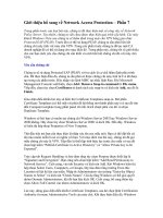
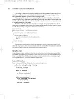
Figure 4.43 illustrates the state transition machines for the PMM states on a
mobile and on an SGSN (assuming RAN is UTRAN).
. From PMM-DETACHED state to PMM-CONNECTED state: A mobile’s
PMM state transitions from PMM-DETACHED to PMM-CONNECTED
242 MOBILITY MANAGEMENT
when the mobile performs GPRS Attach, indicating that it wishes to attach to
the PS domain. To support the GPRS Attach procedure, a signaling connection
needs to be established between the mobile and its serving SGSN (if such a
signaling connection does not already exist).
. From PMM-CONNECTED state to PMM-IDLE state: A mobile’s PMM state
changes from PMM-CONNECTED to PMM-IDLE whenever the signaling
connection between the mobile and its serving SGSN is released. For example,
when the GPRS Attach process is finished, this signaling connection may be
released immediately, which will cause the mobile’s PMM state to change
from PMM-CONNECTED to PMM-IDLE.
. From PMM-IDLE state to PMM-CONNECTED state: A mobile’s PMM state
changes from PMM-IDLE to PMM-CONNECTED whenever a signaling
connection is established between the mobile and a SGSN.
A mobile in PMM-IDLE state may need to establish a signaling connection to
the SGSN for various purposes from time to time. For example, a mobile needs
to establish a signaling connection to the SGSN to perform routing area update
(Section 4.3.3). When this signaling connection is not expected to be needed in
the near future (e.g., after routing area update is completed), it may be released
to allow the mobile’s PMM state to change back to PMM-IDLE.
. From PMM-CONNECTED state to PMM-DETACHED state: A mobile’s
PMM state transitions from PMM-CONNECTED to the PMM-DETACHED
when the GPRS Detach procedure is performed, when the mobile’s GPRS
Attach request is rejected by the SGSN, or when the mobile’s Routing Area
Update (RAU) request is rejected by the SGSN.
. From PMM-IDLE state to PMM-DETACHED state: The PMM state on a
mobile or a SGSN may change from PMM-IDLE to PMM-DETACHED
locally as a result of a local event. For example, the PMM state on a mobile
may change from PMM-IDLE to PMM-DETACHED when the SIM, USIM, or
battery is removed from the mobile. The PMM state on a SGSN may change
Fig. 4.43 3GPP PMM state transition machine on SGSN
4.3 MOBILITY MANAGEMENT IN 3GPP PACKET NETWORKS 243
from PMM-IDLE to PMM-DETACHED when the lifetime of the PMM state
expires.
. From PMM-DETACHED state to PMM-IDLE state: The state of a PMM
context cannot change from PMM-DETACHED to PMM-IDLE directly.
Before a mobile’s PMM context can be in PMM-IDLE state, the mobile’s
PMM context will have to be created first on the SGSN. To create a PDP
context on the SGSN, the mobile has to perform GPRS Attach, which will
cause the mobile’s PMM state to change from PMM-DETACHED to PMM-
CONNECTED first, before it can transition into PMM-IDLE.
While a mobile is in the PMM-CONNECTED state, the mobile’s PDP context
may have been created and activated. This will be the case, for example, if the
mobile has sent user packets over the PS CN domain. When the mobile’s PMM state
transitions from PMM-CONNECTED to PMM-IDLE subsequently, the mobil e’s
existing active PDP contexts will continue to remain in ACTIVE state on the GGSN
and the SGSN. Maintaining an active PDP context in the CN does not consume
much network resource, but it creates significant benefits:
. It reduces the time for a mobile to change from PMM-IDLE state back to
PMM-CONNECTED state when the mobi le needs to send packets to, or
receive packets from, over the PS CN.
. It makes it easier for the PS CN domain to support paging. In particular, an
active PDP context allows the GGSN to always know a mobile’s serving
SGSN. Therefore, the GGSNs do not have to be aware of the paging
operations. Only the SGSNs need to support paging functions.
When a mobile’s serving RNC changes, the SGSN will participate in a process
called Serving RNS Relocation that will relocate the RNC side of the mobile’s I
u
Bearers from the old serving RNC to the new serving RNC (Section 4.3.4). The
Serving RNS Relocation process can only be performed while the mobile is in
PMM-CONNECTED state and it will not change the mobile’s PMM state.
Sometimes, the PMM states of the mobile and the SGSN may lose synch-
ronization. For example, the PMM state on the mobile may be PMM-IDLE while the
SGSN still thinks that the mobile is in the PMM-CONNECTED state. This situation
will be corrected when any one of the following events occurs:
. The mobile performs Routing Area Update, which will change the PMM state
on the mobile into PMM-CONNECTED. After the Routing Area Update, the
mobile’s PMM state on the SGSN will continue to be in PMM-CONNECTED
state. Therefore, synchronization between the PMM states on the mobile and
on the SGSN is regained.
. The SGSN sends data to the mobile but receives messages from the RAN,
indicating that the mobile is not known. This will trigger the paging process
(Section 4.3.6). Paging will cause the mobile to establish a signaling
244 MOBILITY MANAGEMENT
connection and the traffic connections to the SGSN, transferring the PMM
states on both the mobile and the SGSN into PMM-CONNECTED.
4.3.2 Location Management for Packet-Switched Services
4.3.2.1 Location Concepts The RANs and the CN in a 3GPP network use
different location concepts to track mobile terminal locations. The RAN uses the
following location concepts [9]:
. Cell Area (or Cell): A Cell is the geographical area served by one wireless base
station.
. UTRAN Registration Area (URA): A URA is an area covered by a set of cells.
Cells and URAs are used to track the locations of mobiles that are using CS, PS,
or both CS and PS services. Cells and URAs are used only in the RAN and are
invisible to CN nodes.
The CN uses the following location concepts [9]:
. Location Area (LA): A Location Area is a group of Cells used by the CS CN
domain to track the locations of mobiles that are using CS services.
. Routing Area (RA): A Routing Area is a group of Cells used by the PS CN
domain to track the locations of mobiles that are using PS services.
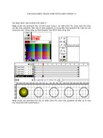
The relations between LAs, RAs, Cells, SGSNs, and MSCs are illustrated in
Figure 4.44. An LA consists one or more Cells that belong to the RNCs that are
Fig. 4.44 3GPP location management for packet services
4.3 MOBILITY MANAGEMENT IN 3GPP PACKET NETWORKS 245
connected to the same MSC/VLR. All Cells in the same URA have to be served by
the same MSC/VLR. In other words, one LA is handled by only one MSC/VLR.
Each LA is identified by a globally unique Location Area Identifier (LAI). When a
mobile moves inside an LA, it does not have to perform location update with the CN
CS domain.
An RA consists of one or more Cells that belong to the RNCs that are connected
to the same SGSN (or one combined SGSN and MSC). In other words, one RA is
handled by only one SGSN. An RA is either the same as an LA or a subset of one and
only one LA [9]. That is, one RA cannot belong to more than one LA, whereas each
LA may contain multiple RAs. Each RA is identified by a globally unique Routing
Area Identifier (RAI).
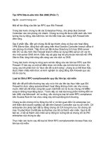
The structures of the LAI and the RAI are illustrated in Figure 4.45 [7]. An LAI is
composed of a Mobile Country Code (MCC), a Mobile Network Code (MNC), and a
Location Area Code (LAC). The MCC identifies the country in which the 3GPP
network is located. The value of the MCC will be the same as the MCC in the IMSIs
allocated to the mobile users in the same country. The MNC identifies a 3GPP
network in that country. The MNC will have the same value as the MNC in the
IMSIs allocated to mobile subscribers of this particular 3GPP network. The LAC
identifies a Location Area within a 3GPP network.
An RAI consists of an LAI and a Routing Area Code (RAC). The LAI field of the
RAI contains an LAI that identifies the Location Area in which the RA resides. The
RAC identifies a Routing Area inside the LA identified by the LAI.
4.3.2.2 Location Tracking 3GPP uses hierarchical location tracking. The
methods and the accuracy level of location tracking for each mobile terminal can
vary over time depending on the activeness level of the mobile (i.e., how likely the
mobile will transfer traffic soon). For location tracking purpose, a mobile’s
Fig. 4.45 Structures of 3GPP Location Area Identifier and Routing Area Identifier
246 MOBILITY MANAGEMENT
activeness level is represented by the mode of its RRC connection. The same RRC
connection is used by the mobile to transport all signaling traffic and user traffic for
its CS and PS services [9], [8].
A mobile’s RRC connection has two modes:
. RRC-CONNECTED mode: A mobile in RRC-CONNECTED mode has an
established RRC connection.
. RRC-IDLE mode: A mobile in RRC-IDLE mode has not established any RRC
connection.
The RRC connection makes up one portion of the signaling connection between
the mobile and the SGSN. The other portion of this signaling connection is the I
u
signaling connection between the RAN (e.g., the RNC in a UTRAN) and the SGSN.
Therefore, when the RRC connection is in RRC-IDLE mode, the mobile’s PMM
state can only be PMM-IDLE or PMM-DETACHED because no signaling con-
nection between the mobile and the SGSN can exist without an RRC connection.
However, when the RRC connection is in RRC-CONNECTED mode, the mobile
may be either in PMM-CONNECTED state or PMM-IDLE state. This is because a
mobile uses a single RRC connection for both CS and PS services; hence, the mobile
can be in RRC-CONNECTED mode and PMM-IDLE state at the same time because
the RRC connection may be present but is currently used only for CS services; i.e.,
no signaling connection is established to the SGSN.
Location tracking is performed as follows depending the mode of the mobile’s
RRC connection [9]:
. When a mobile is in the RRC-IDLE mode (hence, also in PMM-IDLE state),
the mobile’s location is tracked at the RA level by the SGSN s.
A mobile in RRC-IDLE mode will receive the Mobility Management (MM)
system information broadcast by the RNCs at the RRC layer. The MM system
information informs the mobile which Cell and RA it is in currently. A mobile
will initiate RA Update (Section 4.3.3) toward the CN upon receiving MM
system information, indicating that it moved into a new RA.
. When a mobile is in RRC-CONNECTED mode, its location inside the RAN
is tracked at the cell level by the RNCs. To track the mobiles in RRC-
CONNECTED mode, an RNC identifies a mobile by a temporary identifier, the
Radio Network Temporary Identity. The Radio Network Temporary Identity is
assigned to the mobile dynamically by an RNC.
When a mobil e is in RRC-CONNECTED mode, it receives the MM system
information from the serving RNC over the established RRC connection. It
uses the MM system information to determine if it has moved into a new Cell,
RA, or LA.
If the mobile is in RRC-CONNECTED mode and PMM-IDLE state, the
SGSNs will also track the mobile’s location at the RA level. Therefore, the
4.3 MOBILITY MANAGEMENT IN 3GPP PACKET NETWORKS 247
mobile will initiate RA Upda te toward the CN PS domain upon receiving MM
system information, indicating that it has just moved into a new RA.
If the mobile is in RRC-CONNECTED mode and PMM-CONNECTED state,
the mobile’s serving SGSN will know the mobile’s serving RNC because the
serving SGSN maintains a signaling connection through the mobile’s serving
RNC to the mobile. When the mobile’s serving RNC function needs to be
changed to a new RNC as the mobile moves about, the mobile’s serving SGSN
will participate in this change process (i.e., the Serving RNS Relocation
procedure to be described in Section 4.3.4) to ensure that the signaling
connection between the mobile and the SGSN will go through the new serving
RNC.
In addition to performing RA update when crossing RA boundaries, a mobile in
PMM-IDLE state may also perform periodic RA updates.
4.3.3 Routing Area Update
Routing area update in 3GPP achieves several main objectives. It allows the
following:
. The mobile’s serving SGSN to know which RA the mobile is currently in.
. The mobile’s existing active PDP contexts to be updated. For example, if
moving into a new Routing Area also means that the mobile has to use a new
SGSN, a PDP context between the new SGSN and the mobile’s serving GGSN
will need to be established. This ensures that the mobile’s serving GGSN
always knows where to forward user packets destined to the mobile.
A mobile performs RA update when:
. The mobile enters a new Routing Area.
. The mobile’s periodic routing area update timer expires.
. The mobile is directed by the network to re-establish its RRC connection.
. The mobile’s Network Capability changes. A mobile’s Network Capability is a
set of information describing the mobile’s non-radio-related capability. It
includes, for example, information needed for performing ciphering and
authentication.
An RA update may be an intra-SGSN or an inter-SGSN RA update. An intra-
SGSN RA update occurs when the new RA and the old RA connect to the same
SGSN. In other words, the target SGSN is the same as the source SGSN. An inter-
SGSN RA update occurs when the new RA and the old RA connect to the different
SGSNs.
4.3.3.1 Intra-SGSN Routing Area Update The intra-SGSN RA update
procedure (for I
u
mode CN) is illustrated in Figure 4.46.
248 MOBILITY MANAGEMENT
To send uplink signaling messages to perform an RA update, the mobile first
needs to establish an RRC connection with the target RNC if such a channel does not
already exist. This suggests that a mobile has to be in PMM-CONNECTED state for
at least the duration of the RA Update procedure. If the mobile is in PMM-IDLE
state before it starts RA Update, establishing the necessary signaling connection to
the target SGSN changes the mobile’s PMM state into PMM-CONNECTED.
The mobile initiates RA update by sending a Routing Area Update Request to the
target SGSN. The mobile does not have to know whether the RA update is an intra-
SGSN or inter-SGSN RA update; the Routing Area Update Request is the same for
both intra-SGSN and inter-SGSN RA updates.
The Routing Area Update Request carries the following main information
elements:
. P-TMSI: This field carries the P-TMSI that the mobile has been using
immediately before sending the Routing Area Update Request message. This
P-TMSI is likely a P-TMSI assigned to the mobile by the mobile’s source
SGSN.
. Old RAI: The Routing Area Identifier of the previous (old) Routing Area. The
old RAI will be used by the target SGSN to determine whether the RA Update
is intra-SGSN or inter-SGSN by examining whether it also serves the old RA.
. Old P-TMSI Signature: The current P-TMSI signature the mobile has for its
current P-TMSI. Recall that a P-TMSI signature is used by a SGSN to
authenticate a P-TMSI.
Fig. 4.46 3GPP intra-SGSN routing area update procedure
4.3 MOBILITY MANAGEMENT IN 3GPP PACKET NETWORKS 249
. Update Type: The Update Type tells the target SGSN whether the RA Update
is triggered by a change of RA, a periodic RA update, or a combined RA/LA
update.
. Network Capability.
The mobile’s Routing Area Update Request arrives first at the target RNC, which
in turn forwards it to the target SGSN. Forwarding the Routing Area Update Request
from the target RNC to the target SGSN will trigger the establishment of an I
u
signaling connection between the target RNC and the target SGSN for the mobile if
such a connection does not already exist (e.g., if the mobile was in PMM-IDLE state
before sending the Routing Area Update Request).
The target SGSN determines whether the RA update is intra-SGSN or inter-
SGSN RA update by examining the Old RAI carried in the Routing Area Update
Request received from the mobi le. The RA update is intra-SGSN RA update if the
target SGSN also serves the old RA.
The target SGSN needs to authenticate the mobile to determine whether the
Routing Area Update Request can be accepted. As the mobile identifies itself by its
P-TMSI (rather than its IMSI) in the Routing Area Update Request message, the
target SGSN will try to authenticate the mobile by validating the mobile’s P-TMSI
first.
Only the SGSN that assigned the P-TMSI has sufficient information (i.e., the
mobile’s IMSI and the correct P-TMSI Signature for the P-TMSI) to validate the P-
TMSI. As the target SGSN is identical to the source (and serving) SGSN with an
intra-SGSN handoff, the target SGSN should be the SGSN that assigned the old P-
TMSI to the mobile and therefore should be able to validate the P-TMSI locally.
If the P-TMSI validation fails, the target SGSN may initiate further security
procedures to authenticate the mobile.
Upon positive authentication of the mobile, the SGSN updates the mobile’s RAI
it maintains for the mobile. If the mobile was in PMM-CONNECTED state on the
target SGSN, some user traffic destined to the mobile may have already been sent by
the target SGSN to the source RNC and are still buffered at the source RNC waiting
to be delivered to the mobile. As the mobile is now connected to the target RNC that
is different from the source RNC, the source RNC may not be able to deliver these
buffered user traffic over its own radio connections to the mobile. If these traffic
belong to a Radio Access Bearer that requires in-order delivery user packets, the
target SGSN may send a Serving RNS (SRNS) Data Forward Command to the
source RNC to instruct the source RNC to tunnel the user traffic buffered at the
source RNC to the target SGSN. The target SGSN will in turn deliver the traffic to
the mobile before subsequent traffic is sent to the mobile.
The SGSN will also send a Routing Area Update Accept message to the mobile to
inform the mobile that its Routing Area Update Request is accepted. The target
SGSN may assign a new P-TMSI to the mobile. In this case, the new P-TMSI
together with a P-TMSI Signature for the new P-TMSI will be carried in the Routing
Area Update Accept message. The mobile confirms the acceptance of the new P-
250 MOBILITY MANAGEMENT
TMSI by returning a Routing Area Update Complete message to the SGSN, which
completes the RA Update procedure.
4.3.3.2 Inter-SGSN Routing Area Update The inter-S GSN RA update
procedure (for I
u
mode CN) is illustrated in Figure 4.47 [10]. A mobile initiates an
inter-SGSN RA update by sending a Routing Area Update Request to the SGSN in
exactly the same way as in initiating an intra-SGSN RA update. The Routing Area
Update Request has the exact same format and information elements as in the
Routing Area Update Request used in an intra-SGSN RA update.
Just as intra-SGSN RA update, the target SGSN needs to authenticate the mobile
in order to determine if the Routing Area Update Request can be accepted. However,
for an inter-SGSN RA update, the target SGSN is different from the source SGSN.
The mobile’s P-TMSI in the Routing Area Update Request was not assigned by the
target SGSN, but it was instead most likely assigned by the source SGSN. Therefore,
the target SGSN will ask the source SGSN to help validate the P-TMSI. To do so, the
target SGSN first derives the source SGSN from the Old RAI and the P-TMSI
carried in the Routing Area Update Request received from the mobile. Then, the
target SGSN will send a SGSN Context Request message to the source SGSN to ask
the source SGSN to validate the mobile’s P-TMSI. The SGSN Context Request
carries the following information elements: Old P-TMSI, Old RAI, and Old P-TMSI
Signature.
Fig. 4.47 3GPP inter-SGSN routing area update procedure
4.3 MOBILITY MANAGEMENT IN 3GPP PACKET NETWORKS 251
The source SGSN will validate the P-TMSI and act as follows:
. Upon positive validation of the P-TMSI: The source SGSN will send a SGSN
Context Response message back to the target SGSN. The SGSN Context
Response message will carry the mobile’s PMM context and PDP context. The
PMM and PDP contexts contain critical information needed by the target
SGSN to handle the traffic to and from the mobile. For example, the PDP
contexts describe the mobile’s active PDP contexts immediately before the RA
update. The target SGSN will have to initiate the process to update these PDP
contexts on the mobile’s GGSN during the RA update process. Furthermore, if
the mobile was in PMM-CONNECTED state on the source SGSN, the source
SGSN could be sending packets to the mobile immediately before the RA
update. Therefore, the target SGSN will also needs to know the sequence
number of the next user packet the target SGSN should send to the mobile in
order to ensure in-sequence delivery of user packets to the mobile.
Some PDP context inform ation (e.g., sequence number of the next packet to be
sent to the mobile) requested by the target SGSN may be maintained by the
source RNC. In this case, the source SGSN will send an SRNS Context
Request to the source RNC to collect such information. After receiving this
message, the source RNC will stop sending downlink data to the mobile and
returns an SRNS Context Response message, which carries the information
requested by the source SGSN, to the source SGSN.
. Upon negative validation of the P-TMSI: The source SGSN will send an
appropriate error cause to the target SGSN. This will trigger the target SGSN to
initiate the security proce dures directly with the mobile to authenticate the
mobile. If this authentication is also negative, the target SGSN will reject the
mobile’s Routing Area Update Request.
If this authentication is po sitive, the target SGSN will send another SGSN
Context Request message to the source SGSN to retrieve the mobile’s PMM
context and PDP context. This time, the SGSN Context Request will carry the
following information: the mobile’s IMSI, Old RAI, and an indicator (“MS
Validated”) to indicate that the mobile has been positively authenticated by the
target SGSN. The source SGSN will respond with an SGSN Context Response
message carrying the mobile’s PMM context and PDP context if the source
SGSN has these information elements requested by the target SGSN, or an
appropriate error cause if the source does not have the mobile’s PMM context
and PDP context.
After receiving an SGSN Context Response from the source SGSN indicating a
positive validation of the mobile’s P-TMSI, the target SGSN responds with an
SGSN Context ACK message.
If the mobile was in PMM-CON NECTED state on the source SGSN, some user
traffic destined to the mobile may have already been sent by the source SGSN to the
source RNC and are still buffered at the source RNC waiting to be delivered to the
mobile. As the mobile is now connected to the target SGSN that is different from the
252 MOBILITY MANAGEMENT
source SGSN, the source RNC may not be able to deliver these buffered user traffic
over its own radio connections to the mobile. If these traffic belong to a Radio
Access Bearer that requires in-order delivery user packets, the source SGSN may
send an SRNS Data Forward Command to the source RNC to instruct it to tunnel the
user traffic buffered at the source RNC to the source SGSN, which will further
tunnel the traffic to the target SGSN. The target SGSN will in turn deliver the traffic
to the mobile.
After sending the SGSN Context ACK message to the source SGSN , the target
SGSN will also initiate the process to update the mobile’s active PDP contexts in
order to ensure that the mobile’s serving GGSN knows to which SGSN packets
destined to the mobile should be delivered. To illustrate how the mobile’s existing
PDP contexts are updated during the RA Update process, we consider the case where
the mobile’s serving GGSN remains the same after the mobile moves into the new
RA, as shown in Figure 4.47.
To update the mobile’s PDP context, the target SGSN will send an Update PDP
Context Request to the serving GGSN to update each existing PDP context for the
mobile. This will trigger the serving GGSN to update the mobile’s PDP context.
For a successful PDP context update, the target SGSN will also update the
mobile’s location with the HLR, which tracks each mobile’s serving SGSN. When a
GGSN has user packets to send to a mobil e but does not have an active PDP cont ext
for the mobile, the GGSN may query the HLR to find out the address of the mobile’s
current serving SGSN and then use Network-requested PDP Context Activation
(Chapter 2 “Wireless IP Network Architectures”) to establish a PDP context for the
mobile so that it can forward the packets to the mobile.
The SGSN uses the G
r
interface to interact with the HLR for location update. It
sends an Update Location message to the HLR. Upon receiving the Update Location
message, the HLR will inform the source SGSN to cancel its location information
regarding the mobile. The source SGSN will remove the location and service
subscription information it has been maintaining for the mobile. The source SGSN
will also release the I
u
connections between the source SGSN and the source RNC
used by the mobile. In the meantime, the HLR will also send the user’s service
subscription to the target SGSN by sending an Insert Subscribe r Data message to
the target SGSN. The target SGSN records the mobile’s service subscription
information received in this Insert Subscriber Data message and responds to the
HLR with an Insert Subscriber Data ACK message. Now, the HLR will send an
Update Location ACK message back to the target SGSN to indicate that location
update with the HLR is complete.
Upon a successful location update with the HLR, the target SGSN will create a
PMM context for the mobile. Then, the target SGSN will send a Routing Area
Update Accept message to the mobile to inform the mobile that its Routing Area
Update Request is accepted. The target SGSN will assign a new P-TMSI to the
mobile. The new P-TMSI together with a P-TMSI Signature for the new P-TMSI
will be carried in the Routing Area Update Accept message. The mobile confirms
the acceptance of the new P-TMSI by returning a Routing Area Update Complete
message to the SGSN, which completes the RA Update procedure.
4.3 MOBILITY MANAGEMENT IN 3GPP PACKET NETWORKS 253
Routing Area update in 3GPP has an important characteristic: It is integrated with
GPRS routing inside the PS CN. In particular, when a mobile performs Routing Area
update, the host-specific route maintained by the PS CN for forwarding user packets
to and from the mobile will also be updated if necessary. For example, before an
inter-SGSN Routing Area update, the mobile’s host-specific route inside the PS CN
is betwee n the mobile’s serving GGSN and the source SGSN. The inter-SGSN
Routing Area update causes this host-specific route to be changed to between the
mobile’s serving GGSN and the target SGSN.
It is interesting to note that a similar integration of location update and routing is
the foundation for some existing micromobility management protocols designed for
IP networks, such as Cellular IP (Section 4.2.7) and HAWAII (Section 4.2.8).
4.3.4 Serving RNS Relocation
A mobile in PMM-CONNECTED state has a serving RNC. The mobile’s serving
RNC receives user traffic directly from the CN and distributes the traffic over the
RAN to the mobile. The RNS containing a mobile’s serving RNC is referred to as
the mobile’s serving RNS. As shown in Figure 4.48 (a), a mobile’s serving RNS may
forward user traffic via another RNC to the mobile.
When a mobile connects to a target RNC , the target RNC may become the
mobile’s new serving RNC. As an I
u
connection needs to be maintained between the
Fig. 4.48 3GPP data path before and after Serving RNS Relocation and RA Update
254 MOBILITY MANAGEMENT
mobile’s serving RNC and the mobile’s serving SGSN while the mobile is in PMM-
CONNECTED state, the RNC side of the mobile’s I
u
connections needs to be
relocated from the old serving RNC to the new serving RNC. This is achieved using
the Serving RNS Relocation procedure.
In this section, we describe the Serving RNS Relocation procedure under the
assumption that, before the relocation, the mobile’s serving RNC is using the I
ur
interface to forward signaling and user traffic to another RNC, which in turn delivers
the user traffic to the mobile. Such a scenario may occur during or after a soft inter-
RNC handoff. During a soft inter-RNC handoff, the source RNC distributes copies
of user traffic to one or more othe r RNCs, which in turn deliver the user data to the
mobile simultaneously.
Under the assumption that the I
ur
interface is used, the Serving RNS Relocation
procedure can be triggered by RA Update, hard handoff, or soft handoff. When the
I
ur
interface does not exist and hence soft handoff is not possible between the RNCs,
the Serving RNS Relocation procedure may be triggered by RA Update or hard
handoff. Serving RNS Relocation for the case in which the I
ur
interface is not present
is described in Section 4.3.5 together with the hard handoff procedure.
Consider a mobile that moves from a source RNC to a target RNC. Assume that
the source RNC is also the mobile’s serving RNC before the handoff. After the
mobile connects to the target RNC but before Serving RNS Relocation or RA
Update is performed, the user traffic route between the GGSN and the mobile may
look like the one illustrated in Figure 4.48 (a), assuming that the source RNC and the
target RNC are connected to different SGSNs. In particular, user traffic destined to
the mobile continues to be routed by the PS CN to the source RNC, which is still the
mobile’s serving RNC at this moment. The source RNC will then forward the user
traffic to the target RNC. The target RNC will in turn transmit the traffic to the
mobile. After the Serving RNS Relocation and RA Update procedures are
completed, the user traffic route between the mobile and the GGSN will look like the
one shown in Figure 4.48(b). For ease of illustration, Figure 4.48 (b) assumes that
the mobile’s serving GGSN does not change after the Serving RNS relocation and
the RA Update procedures.
The Serving RNS Relocation procedure is illustrated in Figure 4.49 [10]. Only
the source RNC can initiate Serving RNS Relocation. The source RNC decides
whether to initiate Serving RNS Relocation based on measurement results of the
quality of the radio channels to the mobile and based on its knowledge of the RAN
topology.
When the source RNC decides to initiate Serving RNS Relocation, it sends a
RANAP Relocation Required message to the source SGSN. The Relocation
Required message carries the following main information elements:
. Relocation Type: The Relocation Type indicates whether the mobile terminal
should be involved in carrying out the serving RNS relocation procedure, in
particular, whether the mobile’s RRC connection also needs to be relocated
during the serving RNS relocation procedure.
4.3 MOBILITY MANAGEMENT IN 3GPP PACKET NETWORKS 255
– Relocation Type is “UE not Involved”: This indicates that the network
itself carries out the serving RNS relocation procedure and the mobile’s
RRC connection does not need to be relocated during the serving RNS
relocation process. In other words, the mobile has already set up the
necessary RRC connection with the target RNC; no handoff procedure
needs to be performed for the RRC Connection during the serving RNS
relocation procedure. The network only needs to move the RNC side of
the mobile’s I
u
bearers to the target RNC to make it the mobile’s new
serving RNC.
The serving RNS relocation illustrated in Figure 4.49 is not combined
with any handoff procedure. Therefore, the Relocation Type should be
set to “UE not Involved.”
– Relocation Type is “UE Involved”: This indicates that the mobile will
also need to be involved in the serving RNS relocation process to relocate
its RRC connection to the target RNC. The “UE Involved” Relocation
Type is used, for example, in the combined handoff and serving RNS
relocation procedure (Section 4.3.5).
. Source ID: Identifier of the source RNC.
. Target ID: Identifier of the target RNC.
Fig. 4.49 3GPP Serving RNS Relocation
256 MOBILITY MANAGEMENT
. Source RNC to target RNC transparent container: This information element
contains the information needed by the target RNC to perform serving RNC
relocation. It includes the security information regarding the mobile, and the
RRC protocol context that describes the mobile’s RRC connection and the
mobile’s capabilities.
The source SGSN determines if the RNS relocation is intra-SGSN or inter-SGSN
by inspecting the identifiers of the source and the target RNCs. For inter-SGSN
relocation, the source SGSN will send a RANAP Forward Relocation Request
message to the target SGSN to reque st the target SGSN to establish the I
u
connection
for the mobile. The target SGSN will then send a RANAP Relocation Request
message to the target RNC to trigger it to establish the necessary RABs for the
mobile. Recall that each RAB consists of I
u
bearers between the SGSN and the RNC
and Radio Bearers between the mobile and the RNC. To set up the RABs between
the target SGSN and the mobile, the mobile’s I
u
bearers between the source SGSN
and the source RNC need to be relocated between the target SGSN and the target
RNC. There will be no need to establish new Radio Bearers for the mobile. Instead,
the existing Radio Bearers between the mobile and the source RNC will be relocated
between the mobile and the target RNC. After the target RNC has allocated all the
necessary resources for all required RABs, it will send a RANAP Relocation
Request Acknowledge message back to the target SGSN to inform the target SGSN
the I
u
bearers for which RABs have been successfully set up and the I
u
bearers for
which RABs have failed to be set up.
At this point, the resources for transporting user packets between the target RNC
and the target SGSN have been allocated and the target RNC is ready to become the
new serving RNC for the mobile. The target SGSN will send a RANAP Forward
Relocation Response message back to the source SGSN.
Upon receiving the Forward Relocation Response from the target SGSN, the
source SGSN will send a Relocation Command to the source RNC to instruct the
source RNC to start to hand over the role of the serving RNS to the target RNC. This
message will also inform the source RNC which RABs for the mobile should be
released and which ones should be kept for a little longer so that user packets already
received by the source RNC can be forwarded to the target RNC. At this moment,
the source RNC may start to forward downlink user data, which it has already
received, toward the target RNC.
Now, the source RNC will suspend uplink and downlink user data transfer for all
the RABs that require delivery order. Then, the source RNC will transfer its serving
RNC role to the target RNC. To transfer the role of serving RNC, the source RNC
sends a Relocation Commit message, over the I
ur
interface, to the target RNC. This
Relocation Commit message also sends the Serving RNS (SRNS) Contexts for the
mobile from the source RNC to the target RNC. These SRNS Contexts contain
information regarding the RABs between the mobile and the source SGSN.
Upon receiving the Relocation Commit message from the source RNC or
detecting radio connections from the mobile, the target RNC will send a RANAP
Relocation Detect message to the target SGSN to request the SGSN to update the
4.3 MOBILITY MANAGEMENT IN 3GPP PACKET NETWORKS 257
PDP Context for the mobile if necessary (i.e., if the relocation is inter-SGSN).
Immediately after sending out the Relocation Detect message, the target RNC will
start to serve as the serving RNC for the mobile and will start to send RAN Mobility
Information messages to the mobile. The RAN Mobility Information messages
contain the identity of the mobile’s new serving RNC, Location Area Identifier, and
Routing Area Identifier.
The mobile may begin to send uplink traffic toward the target RNC immediately
after the mobile receives the RAN Mobility Information message. The mobile will
also use the information in the received RAN Mobility Information message to
reconfigure itself. After the self reconfiguration, the mobile will send the RAN
Mobility Information Confirm message to the target RNC. This message indicates to
the target RNC that the mobile is ready to receive user traffic from the target RNC.
Upon receiving the RAN Mobility Information Confirm message, the target RNC
will send Relocation Complete to the target SGSN and the target SGSN will in turn
inform the source SGSN of the completion of Serving RNS relocation procedure.
Upon being informed by the target SGSN that the Serving RNS relocation is
completed on the target SGSN, the source SGSN will instruct the source RNC to
release the I
u
Bearers allocated to the mobile.
When the mobile starts communication with the target RNC, the mobile may find
that it has moved into a new RA. In this case, the mobile will initiate the RA Update
procedure.
4.3.5 Hard Handoffs
Handoffs between Node Bs under the same RNC (i.e., intra-RNC handoffs) in a
UTRAN are handled solely by procedures inside the UTRAN. These procedures are
not visible to the PS Domain.
This section focuses on inter-RNC hard handoff, assuming that no I
ur
interface is
implemented. When no I
ur
interface is implemented, inter-RNC handoff can only be
hard handoff.
Before an inter-RNC hard handoff, the source RNC is the mobile’s serving RNC.
During and after an inter-RNC hard handoff, the target RNC will become the
mobile’s new serving RNC. This requires the RNC side of the mobile’s I
u
Bearers to
be relocated from the source RNC to the target RNC during the inter- RNC hard
handoff. Therefore, an inter-RNC hard handoff is usually combined with the Serving
RNC Relocation procedure. This combined procedure is illustrated in Figure 4.50.
The procedure shown in Figure 4.50 also applies to handoff between GSM BSSs,
and between GSM BSS and UTRAN RNS.
Only the source RNC can initiate the inter-RNC hard handoff process. The source
RNC determines whether to initiate the handoff process based on the measurement
results of the radio channel qualities and its knowledge of the RAN topology. It
initiates the combined handoff and serving RNS relocation procedure by first
initiating the serving RNS relocation procedure. The source RNC sends a RANAP
Relocation Required message to the source SGSN and sets the Relocation Type in
this message to “UE Involved” (Section 4.3.4). The “UE Involved” Relocation Type
258 MOBILITY MANAGEMENT
indicates that the mobile will also be involved in the serving RNS relocation process
to relocate its RRC connection to the target RNC (i.e., to perform handoff).
After the source RNC sends out the Relocation Required message to the source
SGSN, the serving RNS relocation procedure proceeds in the same manner as the
Serving RNS Relocation procedure described in Section 4.3.4. In particular, if the
handoff is an inter-SGSN handoff, the source SGSN will send a Forward Relocation
Request to the target SGSN to ask the target SGSN to start the process to relocate the
mobile’s RABs between the mobile and the target SGSN.
Upon receiving the Forward Relocation Request, the target SGSN instructs the
target RNC to relocate the RABs requi red for the mobile by sending a Relocation
Request message to the target RNC. The target RNC proceeds to allocate all the
necessary resources needed to set up the I
u
Bearers for the required RABs. The target
RNC then sends a Relocation Request Acknowledge message back to the target
SGSN.
Unlike the Serving RNS Relocation procedure described in Section 4.3.4, the
Relocation Request Acknowledge here will carry an extra information element—
Target RNC to Source RNC Transparent Container. This information element
contains all the radio-related information that the mobile will need in order to tune
its radio to the radio channels of the target RNS. The Target RNC to Source RNC
Fig. 4.50 3GPP PS Domain hard handoff
4.3 MOBILITY MANAGEMENT IN 3GPP PACKET NETWORKS 259
Transparent Container will be passed on by the target SGSN to the source SGSN,
then by the source SGSN to the source RNC, and finally by the source RNC to the
mobile.
When all the I
u
bearers have been established for the mobile between the target
SGSN and the target RNC and the target RNC is ready to act as the serving RNC for
the mobile, the target SGSN sends a Forward Relocation Response message to the
source SGSN. The Forward Relocation Response message will contain, among other
information, the Target RNC to Source RNC Transparent Container. The Forward
Relocation Response message triggers the source SGSN to send a Relocation
Command to the source RNC to instruct the source RNC to hand over the role of the
serving RNS to the new RNC. The Relocation Command contains, among other
information, the Target RNC to Source RNC Transparent Container received in the
Forward Relocation Response message from the source SGSN.
Upon receiving the Relocation Command message, the source RNC takes the
following main actions:
. Forwarding user data to target RNC: The source RNC begins to forward
downlink user data, which have already arrived at the source RNC, toward the
target RNC. Forwarding of user data from the source RNC to the target RNC is
only performed for the RABs that require such data forwarding.
. Instruct the mobile to relocate its RRC connection to the new RNC: The source
RNC will send an RRC-layer message (referred to as “RRC Message 1” in
Figure 4.50) to instruct the mobile to relocate its Radio Bearers to the new
RNS. This “RRC Message 1” may be different for different radio systems and
different types of handoffs. For example, it may be a Physical Channel
Reconfiguration message for RNS to RNS relocation in a UTRAN, a Handover
Command message for BSS to BSS relocation in a GERAN, or an Intersystem
to UTRAN Handover for BSS to RNS relocation.
For the RABs that require in-sequence delivery of user data, the source RNC
will suspend both uplink and downlink data transfer before instructing the
mobile to relocate its Radio Bearers to the target RNS. This step helps to
ensure that data will be delivered to the target RNC in order.
After the mobile has reconfigured its Radio Bearers and established its RRC
connection to the target RNC, it will send a RRC-layer message (“RRC
Message 2” in Figure 4.50) to inform the target RNC that handoff on the
mobile side has been completed. For example, if “RRC Message 1” is Physical
Channel Relocation for RNS to RNS relocation in a UTRAN, “RRC Message
2” will be a Physical Channel Relocation Complete message.
The source RNC continues the execution of serving RNS relocation by sending a
Forward SRNS Context message to the target RNC (vi a the source SGSN and the
target SGSN). This message provides the mobile’s Serving RNS Context to the
target RNC. An SRNS Context contains information regarding the mobile’s RABs
through the source RNC and can be used by the target RNC to establish I
u
bearers
with the same parameters for the mobile. For each RAB that requires data delivery
260 MOBILITY MANAGEMENT
order, the SRNS Context also contains the sequence numbers of the next downlink
and uplink GTP protocol data units to be transmitted.
When the target RNC detects that the mobile has connected to the target RNC
(which may occur before the target RNC receives “RRC Message 2” from the
mobile), the target RNC will inform the target SGSN by sending a Relocation Detect
message to the target SGSN. For an inter-SGSN hard handoff, the Relocation Detect
message will also trigger the target SGSN to initiate the PDP Context Update
procedure to ensure that the GGSN will start to send user packets destined to the
mobile to the target SGSN.
After the target RNC has detected that the mobile is connected to the target RNC
and received the Forward SRNS Context message with the required data delivery
sequence numbers for the RABs that require delivery order, the target RNC can start
to exchange user data with the mobile on all RABs. However, if the target RNC
receives “RRC Message 2” before it receives the required data delivery sequence
numbers for the RABs that require delivery order, the target RNC can only exchange
user data with the mobile over the RABs that do not require data delivery order, until
it receives the required sequence numbers.
The handoff process completes when the mobile has connected to the target RNS,
the mobile’s PDP context on the mobile’s serving GGSN has been updated, and the
target RNC has received all the required Serving RNS Context information from the
source RNC. The target SGSN informs the source SGSN of the handoff completion
by sending a Forward Relocation Complete message to the source SGSN. This
message will trigger the source SGSN to release the mobile’s I
u
Bearers between the
source SGSN and the source RNC.
After an inter-RNC hard handoff, the mobile may perform Routing Area Update
if it has moved into a new Routing Area as a result of the handoff.
4.3.6 Paging Initiated by Packet-Switched Core Network
When an SGSN wants to send user data to a mobile in PMM-IDLE state, the SGSN
will have to initiate the paging process. Paging initiated by SGSN is illustrated in
Figure 4.51 [10].
Upon receiving downlink user data or signaling messages destined to a mobile in
PMM-IDLE state, the SGSN initiates paging by sending a RANAP Paging message
to every RNC in the Routing Area in which the mobile is located. The RANAP
Paging message carries the following main information:
. Identities of the mobile to be paged: The RANAP Paging message carries the
mobile’s IMSI. If the mobile is using a temporary identity, a P-TMSI, assigned
by the SGSN, the RAN AP Paging mes sage will also contain the mobile’s
P-TMSI.
. CN Domain Identifier: The CN Domain Indicator indicates which CN domain
(i.e., PS CN domain or CS CN domain) initiated this RANAP Paging message.
. Area: The Paging Area in which the mobile is to be paged.
4.3 MOBILITY MANAGEMENT IN 3GPP PACKET NETWORKS 261
Upon receiving a RANAP Paging message, each RNC determines how paging
should be carried out over the air interface. Depending on the way a paging message
is physically delivered by the RNC to the mobile, paging inside the RAN can be
classified into two types:
. Type 1 Paging: Type 1 paging is performed when there is no dedicated RRC
connection between the RNC and the mobile. In this case, the RNC will send a
Paging Type 1 message to the mobile over the Paging Channel, a physical
radio broadcast channel.
Type 1 paging may also be initiated by the RAN, i.e., by an RNC in the RAN.
Therefore, the Pagin g Type 1 message will carry a Paging Originator field that
indicates whether the paging is initiated by the CN or the RAN.
. Type 2 Paging: Type 2 paging will be used when the mobile has a dedicated
RRC connection to the RNC. In this case, the RNC will deliver a Paging Type
2 message to the mobile over this dedicated RRC connection.
Upon receiving a Paging Type 1 or 2 message, the mobile will start the Service
Request procedure (Section 4.3.7) to establish the necessary signaling and traffic
connections with the CN and use them to send uplink signaling messages (to, for
example, respond to the received paging message and to activate the PDP Context)
and user packets.
4.3.7 Service Request Procedure
The Service Request Procedure is used by a mobile in PMM-IDLE state to request
the establishment of a signaling connection between the mobile and the SGSN so
that the mobile can begin to exchange signaling messages with the SGSN. The
Service Request Procedure is also used by a mobile in PMM-CONNECTED state to
request resource reservation for the mobile’s active PDP contexts.
Figure 4.52 illustrates the mobile-initiated Service Request Procedure [10] (for I
u
mode operation). First, the mobile will have to establish an RRC connection with the
RNC, if such a connection does not already exist. Then the mobile sends a Service
Fig. 4.51 3GPP paging in packet switched domain
262 MOBILITY MANAGEMENT
Request message to the SGSN. Upon receiving the Service Request, the SGSN will
perform security procedures to authenticate the mobile and check if it is authorized
to use the network. If the mobile is authorized to use the network, the SGSN takes
actions based on the Service Type in the received Service Request.
. If the Service Type indicates DATA : This means that the mobile has user data to
send over the PS CN domain or expects to receive user data from the PS CN
domain. In this case, a signaling connection between the mobile and the SGSN
will be established first so that the mobile can send signaling messages to the
SGSN. Then, the RABs will be allocated for the mobile’s existing active PDP
contexts usin g the RAB Assignment Procedure described in Chapter 2, if such
RABs do not already exist, to allow the mobile to exchange user data with the
GGSN. A mobile may have an active PDP context but does not have any RAB
if the mobile was in PMM-IDLE state immediately before it started the Service
Request Procedure.
. If the Service Type indicates SIGNALING: This means that the mobile has no
user data to send over the PS CN domain and does not expect to receive any
user data from the PS CN domain at this moment. Instead, the mobile just
wishes to exchange signaling messages with the SGSN. Therefore, only a
signaling connection between the mobile and the SGSN will be established. No
RAB will be allocated for any active PDP context of the mobile. Once the
signaling connection between the mobile and the SGSN has been established,
the mobile may use it to, for example, create and activate new PDP contexts.
Fig. 4.52 3GPP Mobile-initiated Service Request Procedure
4.3 MOBILITY MANAGEMENT IN 3GPP PACKET NETWORKS 263
The Service Request is acknowledged in different ways depending on the Service
Type and the mobile’s PMM state:
. If the mobile is in PMM-CONNECTED state and the Service Type indicates
DATA, the SGSN will respond to the Service Request message by returning a
Service Accept message to the mobile if the SGSN accepts the mobile’s
service request.
. If the Service Type indicates SIGNALING or the mobile is in PMM-IDLE
state, the SGSN does not send any explicit signaling message to the mobile to
indicate the acceptance of the mobile’s Service Request. Instead, the mobile
will learn that its Service Request was successfully received by the SGSN
when the mobile receives certain RRC-layer signaling messages from the
RNC.
After a RAB has been re-established, the QoS profile negotiated for this newly
established RAB may be different from the old negotiated QoS profile maintained in
the PDP contexts on the SGSN, GGSN, and the mobile. In such a case, the SGSN
will trigger the SGSN-initiated PDP Modification procedure to inform the GGSN
and the mobile of the new negotiated QoS profile for the RAB. In case a RAB cannot
be successfully set up, the SGSN may use the SGSN-initia ted PDP Modification
procedure to trigger the mobile and the CN (i.e., the SGSN and the GGSN) to
renegotiate the QoS profile. The SGSN may also use the SGSN-initiated PDP De-
Activation procedure to delete a PDP context if the required RABs cannot be set up
for this PDP context.
The mobile may also use the Modification procedure to request the CN to
renegotiate the QoS profile for a RAB, or use the Mobile-initiated PDP Context De-
Activation procedure to delete an active PDP context.
4.3.8 Handoff and Roaming Between 3GPP and Wireless LANs
As we discussed in Chapter 1, deployment of enterprise and public wireless LANs
(WLANs) have been growing rapidly worldwide. This creates an increasing need for
users to be able to handoff or roam between a cellular network such as 3GPP and an
enterprise or public WLAN.
Here, we discuss how Mobile IP (v4 or v6) can be used to support handoff and
roaming between 3GPP and WLAN. This same approach can also be used to support
handoff/roaming between WLAN and any other cellular network (e.g., GPRS,
EDGE, and 3GPP2). Other IP-based mobility management protocols (e.g., SIP-
based mobility management) may also be used in a similar manner to support
handoffs and roaming between WLAN and a cellular network.
Figure 4.53 illustrates a simplified network configuration for usin g Mobile IP to
support handoff between 3GPP and WLAN. The cellular network shown in the
figure can be any cellular network that can provide mobiles access to an IP network.
For example, the cellular network may be 3GPP, GPRS, EDGE, or 3GPP2. The
264 MOBILITY MANAGEMENT