MOBILE TELECOMMUNICATIONS PROTOCOLS FOR DATA NETWORKS phần 7 pdf
Bạn đang xem bản rút gọn của tài liệu. Xem và tải ngay bản đầy đủ của tài liệu tại đây (159.91 KB, 27 trang )
148 ARCHITECTURE OF WIRELESS LANs
Applications
RFCOMM/SDP
L2 CAP
HCI
LM
Link controller
Baseband
Radio
Application
Presentation
Session
Transport
Network
Data link
Physical
Bluetooth
protocol stack
OSI reference
model
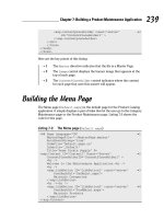
Figure 8.1 The Bluetooth protocol stack and OSI reference model.
function. The data link layer is responsible for transmission, framing, and error control
over a particular link.
The network layer covers the higher end of the link controller, setting up and main-
taining multiple links, and most of the Link Manager (LM) functions. The network layer
is responsible for data transfer across the network, independent of the media and specific
topology of the network. The transport layer covers the high end of the LM and overlaps
the Host Controller Interface (HCI). The transport layer is responsible for reliability and
multiplexing of data transfer across the network to the level provided by the application.
The session layer covers Logical Link Control and Adaptation Protocol (L2CAP) and
the lower end of RFCOMM/SDP, where RFCOMM is a protocol for RS-232 serial cable
emulation and Service Discovery Protocol (SDP) is a Bluetooth protocol that allows a
client to discover the devices offered by a server. The session layer provides the manage-
ment and data flow control services.
The presentation layer covers the main functions of RFCOMM/SDP and provides a
common representation for the application layer data by adding service structure to the
units of data. The application layer is responsible for managing communications between
host applications.
A Bluetooth device is in one of the following states:
• Standby state, in which the device is inactive, no data is being transferred, and the
radio is not switched on. In this state the device is unable to detect any access codes.
• Inquiry state, when a device attempts to discover all the Bluetooth-enabled devices in
its local area.
• Inquiry scan is used by devices to make themselves available to inquiring devices.
• Page state is entered by the master, which transmits paging messages to the intended
slave device.
• Page scan is used by a device to allow paging devices to establish connection with it.
BLUETOOTH 149
• Connection–Active is a state in which the slave moves to the master’s frequency hop
and timing sequence by switching to the master’s clock.
• Connection–Hold mode allows the device to maintain its active member address while
ceasing to support ACL traffic for a certain time to free bandwidth for other operations
such as scanning, paging, inquiry, or low-power sleep.
• Connection–Sniff mode allows the device to listen for traffic by using a predefined
slot time.
• Connection–Park mode allows the device to enter low-power sleep mode by giving up
its active member address and listening for traffic only occasionally.
The SDP is used for device discovery. The messages exchanged between two devices
during inquiry and inquiry scan are shown in Figure 8.2. The inquiring device calls out by
transmitting Identifier (ID) packets containing an IAC. When a scanning device first hears
an inquiry, it waits for a random period and then reenters the scanning state, listening
once more for another ID. This time, if it hears the inquiry, it replies with the Frequency
Hop Synchronization (FHS) packet. Several devices can respond to an inquiry but their
responses are spaced out randomly and do not interfere. The inquirer must keep inquiring
for longer than the range of the random period.
Start inquiry
HCI commands
and events
Baseband
packet
exchange
HCI commands
and events
Inquiring device
Inquiry scanning device
Inquiry result
Inquiry complete
FHS packet
ID packet with inquiry
access code
ID packet with inquiry
access code
ID packet with inquiry
access code
Random delay
before response
Timer periodically
initiates inquiry
scan
Configure scan (inquiry)
Enable scan (inquiry)
•
•
•
•
•
•
•
•
•
•
Figure 8.2 Message sequence chart for inquiry and inquiry scan.
150 ARCHITECTURE OF WIRELESS LANs
Connection accept
Connection complete
Create connection
request
Connection request
Configure scan (page)
Enable scan (page)
LMP link configuration
ACL packet (NULL)
ACL packet (POLL)
ID packet with slave's access code
ID packet with slave's access code
ID packet with slave's access code
ID packet with slave's access code
FHS packet
Both devices move to paging device's hop sequence
HCI commands
and events
HCI commands
and events
Baseband
packet
exchange
Timer periodically
initiates page scan
•
•
•
Figure 8.3 Message sequence chart for paging and page scanning.
A paging procedure is used to establish connection between devices. Figure 8.3 shows
the messages exchanged between two devices during connection establishment. A device
sends out a series of paging ID packets based on the paged device’s address. The page-
scanning device is configured to carry out periodic page scans of a specified duration and
at a specified interval. The scanning device starts a timer and a periodic scan when the
timer elapses. The pager transmits ID packets with the page scanner’s address. If the page
scanner is scanning during this time, it will trigger and receive the ID packet replying
with another ID, using its own address. The page scanner acknowledges the FHS packet
by replying with another ID. The page scanner can extract the necessary parameters,
like Bluetooth clock and active member address, from the FHS packet, to use in the
new connection. The page scanner calculates the pager’s hop sequence and moves to the
connection hop sequence with the pager as master and page scanner as slave. The master
sends a POLL packet to check that the frequency hop sequence switch has happened
correctly. The switch must then respond with an ACL packet. Then follows various LMP
link configuration packets exchange. If required, master and slave can agree to swap the
roles in a master/slave switch.
BLUETOOTH 151
A connection between a host and a Bluetooth device is established in the following steps:
1. Host requests an inquiry.
2. Inquiry is sent using the inquiry hopping sequence.
3. Inquiry scanning devices respond to the inquiry scan with FHS packets that contain
all the information needed to connect with them.
4. The contents of the FHS packets are passed back to the host.
5. The host requests connection to one of the devices that responded to the inquiry.
6. Paging is used to initiate a connection with the selected device.
7. If the selected device is page scanning, it responds to the page.
8. If the page-scanning device accepts the connection, it will start hopping using the
master’s frequency hopping sequence and timing.
The following operations are managed by the link manager (LM), which translates the
Host Controller Interface (HCI) commands.
1. Attaching slaves to a piconet and allocating their active member addresses
2. Breaking connections to detach slaves from a piconet
3. Configuring the link including controlling master/slave switches in which both devices
must simultaneously change roles
4. Establishing ACL data and SCO voice links
5. Putting connections into low power modes: hold, sniff, and park
6. Controlling test modes.
In Bluetooth standard the HCI uses command packets for the host to control the module.
The module uses event packets to inform the host of changes in the lower layers. The
data packets are used to pass voice and data between host and module. The transport
layers carry HCI packets.
The host controls a Bluetooth module by using the following HCI commands:
1. Link control, for instance, setting up, tearing down, and configuring links.
2. Power-saving modes and switching of the roles between master and slave.
3. Direct access to information on the local Bluetooth module and access to information
on remote devices by triggering LMP exchanges.
4. Control of baseband features, for instance, timeouts.
5. Retrieving status information on a module.
6. Invoking Bluetooth test modules for factory testing and for Bluetooth qualification.
L2CAP sends data packets to HCI or to LM. The functions of L2CAP include
• multiplexing between higher layer protocols that allows them to share lower layer links;
• segmentation and reassembly to allow transfer of larger packets than those that lower
layers support;
• group management by providing one-way transmission to a group of other Blue-
tooth devices;
• quality of service management for higher layer protocols.
152 ARCHITECTURE OF WIRELESS LANs
L2CAP provides the following facilities needed by higher layer protocols:
• Establishing links across underlying ACL channels using L2CAP signals;
• Multiplexing between different higher layer entities by assigning each one its own
connection ID;
• Providing segmentation and reassembly facilities to allow large packets to be sent across
Bluetooth connections.
RFCOMM is a protocol for RS-232 serial cable emulation. It is a reliable transport
protocol with framing, multiplexing, and providing modem status, remote line status,
remote port settings, and parameter negotiation. RFCOMM supports devices with internal
emulated serial port and intermediate devices with physical serial port. RFCOMM com-
municates with frames that are carried in the data payload in L2CAP packets. An L2CAP
connection must be set up before an RFCOMM connection can be set up. RFCOMM is
based on the Global System for Mobile communications (GSM) 07.10 standard with a
few minor differences between Bluetooth and GSM cellular phone connections.
SDP server is a Bluetooth device offering services to other Bluetooth devices. Each
SDP server maintains its own database containing information about those services. An
L2CAP channel must be established between SDP client and server, which uses a protocol
service multiplexor reserved for SDP. After the SDP information has been retrieved from
the server, the client must establish a separate connection to use the service. Services
have Universally Unique Identifiers (UUIDs) that describe them.
8.5.2 Bluetooth applications
Bluetooth can be used as a bearer layer in WAP architecture. A WAP server can be
preconfigured with the Bluetooth device address of a WAP server in range, or a WAP
client can find it by conducting an inquiry and then use service discovery to find a WAP
server. The WAP client needs to use SDP to find the RFCOMM server number allocated to
WAP services. The WAP server’s service discovery record identifies whether the service
is a proxy used to access files on other devices, an origin server, which provides its
own files, or both. The provided information includes home URL, service name, and a
set of parameters needed to connect to the WAP service, which are the port numbers
allocated to the various layers of the WAP stack. Once the service discovery information
has been retrieved, an L2CAP link for RFCOMM is established and a WSP session is
set up over this link. The URLs can be requested by Wireless Application Environment
(WAE) across WSP.
The WAP layers use User Datagram Protocol (UDP), Internet Protocol (IP), and Point-
to-Point Protocol (PPP), which allow datagrams to be sent across Bluetooth’s RFCOMM
serial port emulation layer. The WAP components used above the Bluetooth protocol
stack are shown in Figure 8.4.
Te lephony Control protocol Specification (TCS) provides call control signaling to estab-
lish voice and data calls between Bluetooth devices. TCS signals use L2CAP channel with
a Protocol and Service Multiplexor (PSM) reserved for TCS. A separate bearer channel
is established to carry the call, for example, an SCO channel or an ACL channel. TCS
BLUETOOTH 153
WAE
WSP
WTP
WTLS
UDP
IP
PPP
RFCOMM/SDP
L2 CAP
HCI
LM
Link controller
Radio
WAP
Bluetooth
Figure 8.4 WAP on the Bluetooth protocol stack.
does not define handover of calls from one device to another and does not provide a
mechanism for groups of devices to enter into conference calls; only point-to-point links
are supported.
Bluetooth profiles are illustrated in Figure 8.5. The Generic Access Profile (GAP) is
the basic Bluetooth profile used by the devices to establish baseband links.
The serial port profile provides RS-232 serial cable emulation for Bluetooth devices.
It provides a simple, standard way for applications to interoperate, for example, legacy
applications do not need to be modified to use Bluetooth; they can treat Bluetooth link as a
serial cable link. The serial port profile is based on the GSM standard GSM 07.10, which
allows multiplexing of serial connections over one serial link. It supports a communication
end point, for instance, a laptop. It also supports intermediate devices, which form part
of a communications link, for instance, modems.
154 ARCHITECTURE OF WIRELESS LANs
Telephony control protocol specification
Cordless telephony
profile
Intercom
profile
Generic object exchange profile
File transfer profile
Object push profile
Synchronization profile
Serial port profile
Dial-up
networking
profile
FAX
profile
Headset
profile
LAN access
profile
Generic access
profile
Service
discovery
application
profile
Figure 8.5 Bluetooth profiles.
Serial port profile is a part of GAP and consists of dial-up networking, fax, headset,
LAN access, and general object exchange profile, which uses file transfer, object push,
and synchronization.
TCS is a part of GAP and consists of cordless telephony and intercom.
The cordless telephony profile defines a gateway that connects to an external network
and receives incoming calls, and a terminal that receives the calls from the gateway and
provides speech and/or data links to the user. The gateway is the master of a piconet
connecting up to seven terminals at a time; however, because of the limitations on SCO
capacity, only three active voice links can be supported simultaneously. The gateway
can pass calls to the terminals or the terminals can initiate calls and route them through
the gateway. This allows Bluetooth devices that do not have telephony links to access
telephone networks through the gateway.
The intercom profile supports direct point-to-point voice connections between Blue-
tooth devices.
8.5.3 Bluetooth devices
Bluetooth devices use low power modes to keep connections, but switch off receivers
to save battery power. The low power modes include hold, which allows devices to be
BLUETOOTH 155
inactive for a single short period; sniff that allows devices to be inactive except for
periodic sniff slots; and park, which is similar to sniff, except that parked devices give
up their active member address.
Hold mode is used to stop ACL traffic for a specified period of time, but SCO traffic is
not affected. Master and slave can force or request hold mode. A connection enters hold
mode due to a request from the local host, or when a link manager at the remote end of
a connection requests it to hold, or when the local link manager autonomously decides
to put the connection in hold mode. A device enters hold mode when all its connections
are in hold mode.
Sniff mode is used to save power on low data rate links and reduces traffic to periodic
sniff slots. A device in sniff mode only wakes up periodically in prearranged sniff slots.
The master and slave must negotiate the timing of the first sniff slot and the interval at
which further sniff slots follow. They also negotiate the window in which the sniffing
slave will listen for transmissions and the sniff timeout. A device enters sniff mode due
to a request from its own host, or when a link manager at the remote end of a connection
requests or forces it to enter sniff mode. A master can force a slave into sniff mode and
give permission to a slave, which requests to enter sniff mode.
A device entering park mode gives up its active member address and ceases to be
an active member of the piconet. This device cannot transmit and cannot be addressed
directly by the master; however, it wakes up periodically and listens for broadcasts, which
can be used to unpark it. At prearranged beacon instants, a device in park mode wakes
periodically to listen for transmissions from the master during a series of beacon slots.
Park mode allows the greatest power saving.
Quality of service (QoS) capabilities include data rate, delay, and reliability and are
provided by the link manager, which chooses packet types, sets polling intervals, allocates
buffers, link bandwidth, and makes decisions about performing scans. Link managers
negotiate peer to peer to ensure that QoS is coordinated at both ends of a link. For unicast
(point-to-point), a reliable link is provided by the receiver acknowledging packets. The
packets not acknowledged are retransmitted. Broadcast packets are not acknowledged, and
to provide a reliable link, a Bluetooth device can be set to retransmit broadcast packets a
certain number of times.
Figure 8.6 shows Bluetooth devices with different capabilities. These devices are per-
sonal devices, point-to-point devices, point-to-multipoint devices, and scatternet devices.
A personal device connects only to one other preset device. If another device attempts
to connect to a personal device, it refuses the LMP connection request message.
A point-to-point device supports only one ACL data link at a time. When a Bluetooth
device inquires for other devices in the area, it receives FHS packets, which contain all the
information required to connect to the devices, including the clock offset. A point-to-point
device must keep a database of the devices it has discovered.
Point-to-multipoint device can establish links to several devices. This device must
handle QoS balancing between the links through allocation of bandwidth to each link.
Bandwidth requirements are received from the higher layer protocols and lower layers
send QoS violations to the higher layers.
A scatternet is a group of linked piconets joined by common members that can either
be slaves on both piconets or a master of one piconet and a slave on another. Bandwidth
156 ARCHITECTURE OF WIRELESS LANs
Preset
link
Master
Master
Master
Master
Master
Master
Master
Master
Slave
Slave
Slave
Slave
Slave
Slave
Slave
Slave/
master
Slave
Slave
Slave
Slave
Slave
Slave
Slave
Slave
Ad hoc
link
Personal Point-to-point Point-to-multipoint
Scatternet
Scatternet
Scatternet
Figure 8.6 Bluetooth devices with different capabilities.
is reduced in scatternet by the time taken to switch between piconets, which should be
done infrequently. Devices are absent from one piconet when present on the other, and
this absence should be managed if maximum efficiency is required. Managing piconets
involves calculation and negotiation of parameters for QoS, and possibly beacon slots,
sniff slots, or hold times.
A device manager performs as an interpreter between applications and Bluetooth pro-
tocols as shown in Figure 8.7. Applications requesting links and discovering devices use
the device manager, which also has the information about configuration control. A device
manager handles set up, tear down, and configuration of the baseband links, QoS param-
eters and trade-offs, management of higher layer links, device discovery, and information
caching. The device manager has an interface to HCI, RFCOMM, and LC2CAP.
SUMMARY 157
MMI (Man− Machine Interface)
Configuration
application
Application Application
Device manager
SDP
RFCOMM
Serial port
application
HCI
L2 CAP
Baseband layer
Figure 8.7 Bluetooth protocol stack with device manager.
8.6 SUMMARY
The use of Spread Spectrum is especially important as it allows many more users to occupy
the band at any given time and place than if they were all static on separate frequencies.
With any radio system, one of the greatest limitations is available bandwidth, and so the
ability to have many users operate simultaneously in a given environment is critical for
the successful deployment of WLAN.
The application of Infrared is as a docking function and in applications in which the
power available is extremely limited, such as a pager or PDA.
158 ARCHITECTURE OF WIRELESS LANs
There are two methods of Spread Spectrum modulation: Direct Sequence Spread Spec-
trum (DSSS) and Frequency Hopping Spread Spectrum (FHSS).
IEEE 802.11 appears to higher layers [Logical Link Control (LLC)] as an IEEE
802 LAN, which requires that the IEEE 802.11 network handle station mobility within
the MAC sublayer and meets the reliability assumptions that LLC makes about the
lower layers.
In Bluetooth standard the HCI uses command packets for the host to control the module.
The module uses event packets to inform the host of changes in the lower layers. The
data packets are used to pass voice and data between host and module. The transport
layers carry HCI packets.
Bluetooth can be used as a bearer layer in WAP architecture. A WAP server can be
preconfigured with the Bluetooth device address of a WAP server in range, or a WAP client
can find it by conducting an inquiry and then use service discovery to find a WAP server.
PROBLEMS TO CHAPTER 8
Architecture of wireless LANs
Learning objectives
After completing this chapter, you are able to
• demonstrate an understanding of wireless LANs;
• explain the role of RF;
• explain the role of IR;
• explain the difference between DSSS and FHSS;
• demonstrate an understanding of IEEE 802.11 WLAN architecture;
• explain the role of STA;
• explain the role of BSS and ESS;
• explain the role of DS, DSM, and DSS;
• demonstrate an understanding of Bluetooth architecture;
• explain the states of a Bluetooth device;
• explain how a c onnection is established between a host and Bluetooth device;
• explain the role of the HCI;
• explain the functions of L2CAP.
Practice problems
8.1: What are the WLAN’s operating speeds?
8.2: What is the radio frequency (RF) band in which the LANs operate?
8.3: Where is RF used?
8.4: Where is IR used?
8.5: What is the function of DSSS?
8.6: What is the function of FHSS?
8.7: What is the addressable unit in IEEE 802.11?
PROBLEMS TO CHAPTER 8 159
8.8: What is BSS?
8.9: What is the architecture of the DS?
8.10: What is the role of a portal?
8.11: What are the architectural services of IEEE 802.11?
8.12: What are the possible states of a Bluetooth device?
8.13: How is a connection between a host and Bluetooth device established?
8.14: How does the host control a Bluetooth module?
8.15: What are the functions of L2CAP?
Practice problem solutions
8.1: A WLAN is capable of operating at speeds in the range of 1, 2, or 11 Mbps
depending on the actual system. These speeds are supported by the standard for
WLAN networks defined by the international body, the IEEE.
8.2: WLAN communications take place in a part of the radio spectrum that is designated
as license-free. In this band, 2.4 to 2.5 GHz, users can operate without a license
as long as they use equipment that has been type-approved for use in the license-
free bands.
8.3: RF is very capable of being used for applications in which communications are not
line-of-sight and are over longer distances. The RF signals travel through walls and
communicate where there is no direct path between the terminals.
8.4: Infrared is primarily used for very short distance communications, less than 3 ft
where there is an LOS connection. It is not possible for the Infrared light to penetrate
any solid material; it is even attenuated greatly by window glass, so it is really not
a useful technology in comparison to Radio Frequency for use in a WLAN system.
The application of Infrared is as a docking function and in applications in which
the power available is extremely limited such as a pager or PDA. The standard for
such products is called Infrared Data Association (IrDA), which has been used by
Hewlett Packard, IBM, and others. This is found in many notebook and laptop PCs
and allows a connectionless docking facility up to 1 Mbps to a desktop machine
and up to two feet, line of sight.
8.5: A DSSS system takes a signal at a given frequency and spreads it across a band
of frequencies where the center frequency is the original signal. The spreading
algorithm, which is the key to the relationship of the spread range of frequencies,
changes with time in a pseudorandom sequence that appears to make the spread
signal a random noise source.
8.6: Frequency Hopping Spread Spectrum (FHSS) is based on the use of a signal at
a given frequency that is constant for a small amount of time and then moves to
a new frequency. The sequence of different channels determined for the hopping
pattern, that is, where the next frequency will be to engage with this signal source,
is pseudorandom.
8.7: In IEEE 802.11 the addressable unit is a station (STA), which is a message desti-
nation, but not (in general) a fixed location. IEEE 802.11 handles both mobile and
portable stations. MSs access the LAN while in motion, whereas a Portable Station
(PS) can be moved between locations but it is used only at a fixed location. MSs
160 ARCHITECTURE OF WIRELESS LANs
are often battery powered, and power management is an important consideration
since we cannot assume that a station’s receiver will always be powered on.
8.8: The IEEE 802.11 architecture provides a WLAN supporting station mobility trans-
parently to upper layers. The Basic Service Set (BSS) is the basic building block
consisting of member stations remaining in communication. If a station moves out
of its BSS, it can no longer directly communicate with other members of the BSS.
The IBSS is the most basic type of IEEE 802.11 LAN, and may consist of at
least two stations that can communicate directly. This LAN is formed only as long
as it is needed, and is often referred to as an ad hoc network. The association
between an STA and a BSS is dynamic since STAs turn on and off, come within
range and go out of range.
8.9: A BSS may form the Distribution System (DS), which is an architectural component
used to interconnect BSSs. IEEE 802.11 logically separates the Wireless Medium
(WM) from the Distribution System Medium (DSM). Each logical medium is used
for different purposes by a different component of the architecture. The IEEE 802.11
LAN architecture is specified independently of the physical characteristics of any
specific implementation. The DS enables mobile device support by providing the
logical services necessary to handle address-to-destination mapping and seamless
integration of multiple BSSs. An Access Point (AP) is an STA that provides access
to the DS by providing DS services in addition to acting as an STA. The data
move between a BSS and the DS via an AP. All APs are also STAs and they are
addressable entities. The addresses used by an AP for communication on the WM
and on the DSM are not necessarily the same.
The DS and BSSs allow IEEE 802.11 to create a wireless network of arbitrary
size and complexity called the Extended Service Set (ESS) network. The ESS net-
work appears the same to an LLC layer as an IBSS network. Stations within an
ESS may communicate and MSs may move from one BSS to another (within the
same ESS) transparently to LLC.
8.10: A portal is the logical point at which MAC Service Data Units (MSDUs) from an
integrated non-IEEE 802.11 LAN enter the IEEE 802.11 DS. All data from non-
IEEE 802.11 LANs enter the IEEE 802.11 architecture via a portal, which provides
logical integration between the IEEE 802.11 architecture and existing wired LANs.
A device may offer both the functions of an AP and a portal, for example, when a
DS is implemented from IEEE 802 LAN components.
8.11: Architectural services of IEEE 802.11 are as follows: authentication, association,
deauthentication, disassociation, distribution, integration, privacy, reassociation, and
MSDU delivery. These services are provided either by stations as the Station Service
(SS) or by the DS as the Distribution System Service (DSS).
The SS includes authentication, deauthentication, privacy, and MSDU delivery.
The SS is present in every IEEE 802.11 station, including APs and is specified for
use by MAC sublayer entities.
The DSSs include association, disassociation, distribution, integration, and reas-
sociation. The DSSs are provided by the DS and accessed by an AP, which
is an STA that also provides DSSs. DSSs are specified for use by MAC sub-
layer entities.
PROBLEMS TO CHAPTER 8 161
8.12: A Bluetooth device is in one of the following states:
• Standby state, in which the device is inactive, no data is being transferred, and
the radio is not switched on. In this state the device is unable to detect any
access codes.
• Inquiry state, when a device attempts to discover all the Bluetooth-enabled
devices in its local area.
• Inquiry scan is used by devices to make themselves available to inquiring devices.
• Page state is entered by the master, which transmits paging messages to the
intended slave device.
• Page scan is used by a device to allow paging devices to establish connection
with it.
• Connection–Active is a state in which the slave moves to the master’s frequency
hop and timing sequence by switching to the master’s clock.
• Connection–Hold mode allows the device to maintain its active member address
while ceasing to support ACL traffic for a certain time to free bandwidth for
other operations such as scanning, paging, inquiry, or low-power sleep.
• Connection–Sniff mode allows the device to listen for traffic by using a prede-
fined slot time.
• Connection–Park mode allows the device to enter low-power sleep mode by
giving up its active member address and listening for traffic only occasionally.
8.13: A connection between a host and Bluetooth device is established in the follow-
ing steps:
1. Host requests an inquiry.
2. Inquiry is sent using the inquiry hopping sequence.
3. Inquiry scanning devices respond to the inquiry scan with FHS packets that
contain all the information needed to connect with them.
4. The contents of the FHS packets are passed back to the host.
5. The host requests connection to one of the devices that responded to the inquiry.
6. Paging is used to initiate a connection with the selected device.
7. If the selected device is page scanning, it responds to the page.
8. If the page-scanning device accepts the connection, it will start hopping using
the master’s frequency hopping sequence and timing.
8.14: The host controls a Bluetooth module by using the following HCI commands:
1. Link control, for instance, setting up, tearing down, and configuring links.
2. Power-saving modes and switching of the roles between master and slave.
3. Direct access to information on the local Bluetooth module and access to infor-
mation on remote devices by triggering LMP exchanges.
4. Control of baseband features, for instance, timeouts.
5. Retrieving status information on a module.
6. Invoking Bluetooth test modules for factory testing and for Bluetooth qualification.
8.15: Logical Link Control and Adaptation Protocol (L2CAP) send data packets to HCI
or to LM. The functions of L2CAP include
162 ARCHITECTURE OF WIRELESS LANs
• multiplexing between higher layer protocols that allow them to share lower
layer links;
• segmentation and reassembly to allow transfer of larger packets than those that
lower layers support;
• group management by providing one-way transmission to a group of other Blue-
tooth devices; and
• Quality-of-service management for higher layer protocols.
L2CAP provides the following facilities needed by higher layer protocols:
• Establishing links across underlying ACL channels using L2CAP signals.
• Multiplexing between different higher layer entities by assigning each one its
own connection ID.
• Providing segmentation and reassembly facilities to allow large packets to be
sent across Bluetooth connections.
9
Routing protocols in mobile
and wireless networks
Mobile and wireless networks allow the users to access information and services elec-
tronically, regardless of their geographic location. There are infrastructured networks and
infrastructureless (ad hoc) networks. Infrastructured network consists of a network with
fixed and wired gateways. A mobile host communicates with a Base Station (BS) within
its communication radius. The mobile unit can move geographically while it is commu-
nicating. When it goes out of range of one BS, it connects with a new BS and starts
communicating through it by using a handoff. In this approach, the BSs are fixed.
In contrast to infrastructure-based networks, in ad hoc networks all nodes are mobile
and can be connected dynamically in an arbitrary manner. All nodes of these networks
behave as routers and take part in discovery and maintenance of routes to other nodes in
the network. Ad hoc networks are very useful in emergency search-and-rescue operations,
meetings, or conventions in which persons wish to quickly share information and data
acquisition operations in inhospitable terrain.
An ad hoc network is a collection of mobile nodes forming a temporary network
without the aid of any centralized administration or standard support services regularly
available in conventional networks. We assume that the mobile hosts use wireless radio
frequency transceivers as their network interface, although many of the same principles
will apply to infrared and wire-based networks. Some form of routing protocol is necessary
in these ad hoc networks since two hosts wishing to exchange packets may not be able
to communicate directly.
Wireless network interfaces usually operate at significantly slower bit rates than their
wire-based counterparts. Frequent flooding of packets throughout the network, a mecha-
nism many protocols require, can consume significant portions of the available network
bandwidth. Ad hoc routing protocols must minimize bandwidth overhead at the same time
as they enable routing.
Ad hoc networks must deal with frequent changes in topology. Mobile nodes change
their network location and link status on a regular basis. New nodes may unexpectedly join
164 ROUTING PROTOCOLS IN MOBILE AND WIRELESS NETWORKS
the network or existing nodes may leave or be turned off. Ad hoc routing protocols must
minimize the time required to converge after the topology changes. A low convergence
time is more critical in ad hoc networks because temporary routing loops can result in
packets being transmitted in circles, further consuming valuable bandwidth.
The routing protocols meant for wired networks cannot be used for mobile ad hoc
networks because of the mobility of networks. The ad hoc routing protocols can be
divided into two classes: table-driven and on-demand routing, on the basis of when and
how the routes are discovered. In table-driven routing protocols, consistent and up-to-
date routing information to all nodes is maintained at each node, whereas in on-demand
routing the routes are created only when desired by the source host. We discuss current
table-driven protocols as well as on-demand protocols.
9.1 TABLE-DRIVEN ROUTING PROTOCOLS
In table-driven routing protocols, each node maintains one or more tables containing
routing information to every other node in the network. All nodes update these tables so
as to maintain a consistent and up-to-date view of the network. When the network topology
changes, the nodes propagate update messages throughout the network in order to maintain
a consistent and up-to-date routing information about the whole network. These routing
protocols differ in the method by which the information regarding topology changes is
distributed across the network and in the number of necessary routing-related tables.
9.1.1 Destination-sequenced distance-vector routing
Destination-Sequenced Distance-Vector Routing (DSDV) is an adoption of a conven-
tional routing protocol to ad hoc networks. DSDV is based on the Routing Information
Protocol (RIP) used in parts of the Internet. Consequently, DSDV only makes use of
bidirectional links.
In DSDV, packets are routed between nodes of an ad hoc network using a Routing
Ta ble (RT) stored at each node. Each RT at each node contains a list of the addresses of
every other node in the network. Along with each node’s address, the table contains the
address of the next hop for a packet to take in order to reach the node.
DSDV generates and maintains the RTs. Every time the network topology changes,
the RT in every node needs to be updated. In addition to the destination address and
next hop address, RTs maintain the route metric (the number of hops) and the route
sequence number.
Periodically, or immediately when network topology changes are detected, each node
will broadcast an RT update packet. The update packet starts out with a metric of one.
This signifies to each receiving neighbor that it is one hop away from the node. The
neighbors will increment this metric and then retransmit the update packet. This process
repeats itself until every node in the network has received a copy of the update packet
with a corresponding metric. If a node receives duplicate update packets, the node will
only consider the update packet with the smallest metric and ignore the remaining ones.
TABLE-DRIVEN ROUTING PROTOCOLS 165
To distinguish stale update packets from valid ones, each update packet is tagged by the
original node with a sequence number. The sequence number is a monotonically increasing
number that uniquely identifies each update packet from a given node. Consequently, if
a node receives an update packet from another node, the sequence number must be equal
to or greater than the sequence number already in the RT; otherwise the update packet is
stale and ignored. If the sequence number matches the sequence number in the RT, then
the metric is compared and updated.
Each time an update packet is forwarded, the packet not only contains the address of
the destination but it also contains the address of the transmitting node. The address of
the transmitting node is entered into the RT as the next hop. The update packets with the
higher sequence numbers are always entered into the RT, regardless of whether they have
a higher metric or not.
Each node must periodically transmit its entire RT to its neighbors using update pack-
ets. The neighbors will update their tables on the basis of this information, if required.
Likewise, each node will listen to its neighbors update packets and update its own RT.
Mobile nodes cause broken links as they move from place to place. The broken link
may be detected by the communication hardware, or it may be inferred if no broadcasts
have been received for a while from a former neighbor. A broken link is described as
having a metric of infinity. Since this qualifies as a substantial route change, the detecting
node will broadcast an update message for the lost destination. This update message will
have a new sequence number and a metric of infinity. This will essentially cause the RT
entries for the lost node to be flushed from the network. Routes to the lost node will be
established again when the lost node sends out its next broadcast.
To avoid nodes and their neighbors generating conflicting sequence numbers when
the topology changes, nodes only generate even sequence numbers for themselves, and
neighbors responding to link changes only generate odd sequence numbers.
DSDV is based on a conventional routing protocol, RIP, adopted for use in ad hoc
networks. Routing is achieved by using RTs maintained by each node. The bulk of the
complexity in DSDV is in generating and maintaining these RTs.
DSDV requires nodes to periodically transmit RT update packets, regardless of network
traffic. These update packets are broadcast throughout the network so every node in the
network knows how to reach every other node. As the number of nodes in the network
grows, the size of the RTs and the bandwidth required to update them also grows. This
overhead is DSDV’s main weakness, as Broch et al. found in their simulations of 50-node
networks. Furthermore, whenever the topology changes, DSDV is unstable until update
packets propagate throughout the network. Broch found DSDV to be the most difficult in
dealing with high rates of node mobility.
Every mobile station maintains an RT that lists all available destinations, the number of
hops to reach the destination, and the sequence number assigned by the destination node.
The sequence number is used to distinguish stale routes from new ones and thus avoid
the formation of loops. The stations periodically transmit their RTs to their immediate
neighbors. A station also transmits its RT if a significant change has occurred in its
table from the last update sent. Thus, the update is both time-driven and event-driven.
The RT updates can be sent in two ways: a full dump or an incremental update. A full
dump sends the full RT to the neighbors and could span many packets, whereas in an
166 ROUTING PROTOCOLS IN MOBILE AND WIRELESS NETWORKS
incremental update, only those entries from the RT are sent that have a metric change
since the last update, and they must fit in a packet. If there is space in the incremental
update packet, then those entries may be included whose sequence number has changed.
When the network is relatively stable, incremental updates are sent to avoid extra traffic
and full dumps are relatively infrequent. In a fast-changing network, incremental packets
can grow, and full dumps will be more frequent. Each route update packet, in addition to
the RT information, also contains a unique sequence number assigned by the transmitter.
The route labeled with the highest (i.e., the most recent) sequence number is used. If
two routes have the same sequence number, then the route with the best metric (i.e., the
shortest route) is used. On the basis of the past history, the stations estimate the settling
time of routes. The stations delay the transmission of a routing update by settling time so
as to eliminate those updates that would occur if a better route was found very soon.
9.1.2 The wireless routing protocol
The Wireless Routing Protocol (WRP) is a table-based distance-vector routing protocol.
Each node in the network maintains a Distance table, an RT, a Link-cost table, and a
Message Retransmission List (MRL). The Distance table of a node x contains the distance
of each destination node yvia each neighbor z of x. It also contains the downstream
neighbor of z through which this path is realized. The RT of node x contains the distance
of each destination node y from node x, the predecessor and the successor of node x
on this path. It also contains a tag to identify if the entry is a simple path, a loop, or
invalid. Storing predecessor and successor in the table is beneficial in detecting loops
and avoiding counting-to-infinity problems. The Link-cost table contains cost of link to
each neighbor of the node and the number of timeouts since an error-free message was
received from that neighbor. The MRL contains information to let a node know which
of its neighbors has not acknowledged its update message and to retransmit the update
message to that neighbor.
Nodes exchange RTs with their neighbors using update messages periodically as well
as on link changes. The nodes present on the response list of update message (formed
using MRL) are required to acknowledge the receipt of the update message. If there is
no change in RT since the last update, the node is required to send an idle Hello message
to ensure connectivity. On receiving an update message, the node modifies its distance
table and looks for better paths using new information. Any new path so found is relayed
back to the original nodes so that they can update their tables. The node also updates its
RT if the new path is better than the existing path. On receiving an Acknowledgement
ACK, the node updates its MRL. A unique feature of this algorithm is that it checks
the consistency of all its neighbors every time it detects a change in link of any of its
neighbors. A consistency check in this manner helps eliminate looping situations in a
better way and it also has fast convergence.
9.1.3 Global state routing
Global State Routing (GSR) is similar to DSDV. It takes the idea of link state routing
but improves it by avoiding flooding of routing messages. In this algorithm, each node
TABLE-DRIVEN ROUTING PROTOCOLS 167
maintains a Neighbor list, a Topology table, a Next Hop table, and a Distance table.
Neighbor list of a node contains the list of its neighbors (here all nodes that can be heard
by a node are assumed to be its neighbors). For each destination node, the Topology table
contains the link state information as reported by the destination and the timestamp of the
information. For each destination, the Next Hop table contains the next hop to which the
packets for this destination must be forwarded. The Distance table contains the shortest
distance to each destination node.
The routing messages are generated on a link change as in link state protocols. On
receiving a routing message, the node updates it’s Topology table if the sequence number
of the message is newer than the sequence number stored in the table. After this, the node
reconstructs its RT and broadcasts the information to its neighbors.
9.1.4 Fisheye state routing
Fisheye State Routing (FSR) is an improvement of GSR. The large size of update messages
in GSR wastes a considerable amount of network bandwidth. In FSR, each update message
does not contain information about all nodes. Instead, it exchanges information about
closer nodes more frequently than it does about farther nodes, thus reducing the update
message size. Each node receives accurate information about neighbors, and the detail
and accuracy of information decreases as the distance from the node increases. The scope
is defined in terms of the nodes that can be reached in a certain number of hops. The
center node has the most accurate information about the other nodes. Even though a node
does not have accurate information about distant nodes, the packets are routed correctly
because the route information becomes more and more accurate as the packet moves
closer to the destination. FSR scales well to large networks as the overhead is controlled
in this scheme.
9.1.5 Hierarchical state routing
The characteristic feature of Hierarchical State Routing (HSR) is multilevel clustering
and logical partitioning of mobile nodes. The network is partitioned into clusters and
a cluster head elected as in a cluster-based algorithm. In HSR, the cluster heads again
organize themselves into clusters and so on. The nodes of a physical cluster broadcast
their link information to each other. The cluster head summarizes its cluster’s information
and sends it to the neighboring cluster heads via the gateway. These cluster heads are
members of the cluster on a level higher and they exchange their link information as well
as the summarized lower-level information among themselves and so on. A node at each
level floods to its lower level the information that it obtains after the algorithm has run
at that level. The lower level has a hierarchical topology information. Each node has a
hierarchical address. One way to assign hierarchical address is to use the cluster numbers
on the way from the root to the node. A gateway can be reached from the root via more
than one path; thus, a gateway can have more than one hierarchical address. A hierarchical
address is enough to ensure delivery from anywhere in the network to the host.
In addition, nodes are also partitioned into logical subnetworks and each node is
assigned a logical address <subnet, host>. Each subnetwork has a Location Manage-
ment Server (LMS). All the nodes of that subnet register their logical address with the
168 ROUTING PROTOCOLS IN MOBILE AND WIRELESS NETWORKS
LMS. The LMS advertise their hierarchical address to the top levels and the information
is sent down to all LMS too. The transport layer sends a packet to the network layer with
the logical address of the destination. The network layer finds the destination’s LMS from
its LMS and then sends the packet to it. The destination’s LMS forwards the packet to
the destination. Once the source and destination know each other’s hierarchical addresses,
they can bypass the LMS and communicate directly. Since logical address/hierarchical
address is used for routing, it is adaptable to network changes.
9.1.6 Zone-based hierarchical link state routing protocol
In Zone-based Hierarchical Link State Routing Protocol (ZHLS), the network is divided
into nonoverlapping zones. Unlike other hierarchical protocols, there is no zone-head.
ZHLS defines two levels of topologies – node level and zone level. A node level topology
tells how nodes of a zone are connected to each other physically. A virtual link between
two zones exists if at least one node of a zone is physically connected to some node of
the other zone. Zone level topology tells how zones are connected together. There are
two types of Link State Packets (LSP) as well – node LSP and zone LSP. A node LSP of
a node contains its neighbor node information a nd is propagated with the zone, whereas
a zone LSP contains the zone information and is propagated globally. Each node has
full node connectivity knowledge about the nodes in its zone and only zone connectivity
information about other zones in the network. Given the zone id and the node id of a
destination, the packet is routed on the basis of the zone id till it reaches the correct zone.
Then in that zone, it is routed on the basis of the node id. A <zone id, node id> of the
destination is sufficient for routing, so it is adaptable to changing topologies.
9.1.7 Cluster-head gateway switch routing protocol
Cluster-head Gateway Switch Routing (CGSR) uses as basis the DSDV Routing algorithm.
The mobile nodes are aggregated into clusters and a cluster head is elected. All nodes
that are in the communication range of the cluster head belong to its cluster. A gateway
node is a node that is in the communication range of two or more cluster heads. In
a dynamic network, a cluster-head scheme can cause performance degradation due to
frequent cluster-head elections, so CGSR uses a Least Cluster Change (LCC) algorithm.
In LCC, cluster-head change occurs only if a change in network causes two cluster heads to
come into one cluster, or one of the nodes moves out of the range of all the cluster heads.
The general algorithm works in the following manner: the source of the packet transmits
the packet to its cluster head. From this cluster head, the packet is sent to the gateway
node that connects this cluster head and the next cluster head along the route to the
destination. The gateway sends it to that cluster head and so on till the destination cluster
head is reached in this way. The destination cluster head then transmits the packet to the
destination.
Each node maintains a cluster member table that has mapping from each node to
its respective cluster head. Each node broadcasts its cluster member table periodically
and updates its table after receiving other node’s broadcasts using the DSDV algorithm.
ON-DEMAND ROUTING PROTOCOLS 169
In addition, each node also maintains an RT that determines the next hop to reach the
destination cluster.
On receiving a packet, a node finds the nearest cluster head along the route to the
destination according to the cluster member table and the RT. Then it consults its RT to
find the next hop in order to reach the cluster head selected in step one and transmits the
packet to that node.
9.2 ON-DEMAND ROUTING PROTOCOLS
In contrast to table-driven routing protocols, all up-to-date routes are not maintained at
every node; instead, the routes are created as and when they are required. When source
wants to send a packet to destination, it invokes the route discovery mechanisms to find
the path to the destination. The route remains valid till the destination is reachable or
until the route is no longer needed.
9.2.1 Temporally ordered routing algorithm
Temporally Ordered Routing Algorithm (TORA) is a distributed routing protocol based
on a link reversal algorithm. It is designed to discover routes on-demand, provide multiple
routes to a destination, establish routes quickly, and minimize communication overhead
by localizing the reaction to topological changes when possible. Route optimality (the
shortest-path routing) is considered of secondary importance, and longer routes are often
used to avoid the overhead of discovering newer routes. It is also not necessary (nor
desirable) to maintain routes between every source/destination pair at all times.
The actions taken by TORA can be described in terms of water flowing downhill
toward a destination node through a network of tubes that model the routing state of the
network. The tubes represent links between nodes in the network, the junctions of the
tubes represent the nodes, and the water in the tubes represents the packets flowing toward
the destination. Each node has a height with respect to the destination that is computed
by the routing protocol. If a tube between two nodes becomes blocked such that water
can no longer flow through it, the height of the nodes is set to a height greater than that
of any neighboring nodes, such that water will now flow back out of the blocked tube
and find an alternate path to the destination.
At each node in the network, a logically separate copy of TORA is run for each
destination. When a node needs a route to a particular destination, it broadcasts a route
query packet containing the address of the destination. This packet propagates through
the network until it reaches either the destination or an intermediate node having a route
to the destination. The recipient of the query packet then broadcasts an update packet
listing its height with respect to the destination (if the recipient is the destination, this
height is 0). As this packet propagates back through the network, each node that receives
the update sets its height to a value greater than the height of the neighbor from which
the update was received. This has the effect of creating a series of directed links from the
original sender of the query to the node that initially generated the update.
170 ROUTING PROTOCOLS IN MOBILE AND WIRELESS NETWORKS
When a node discovers that a route to a destination is no longer valid, it adjusts its
height so that it is at a local maximum with respect to its neighbors and transmits an
update packet.
When a node detects a network partition, where a part of the network is physically
separated from the destination, the node generates a clear packet that resets the routing
state and removes invalid routes from the network.
TORA is a routing layer above network level protocol called the Internet Mobile Ad hoc
Networking (MANET) Encapsulation Protocol (IMEP). IMEP is designed to support the
operation of many routing algorithms, network control protocols, or other upper layer pro-
tocols intended for use in mobile ad hoc networks. The protocol incorporates mechanisms
for supporting link status and neighbor connectivity sensing, control packet aggregation
and encapsulation, one-hop neighbor broadcast reliability, multipoint relaying, network-
layer address resolution, and provides hooks for interrouter authentication procedures.
In TORA, each node must maintain a structure describing the node’s height as well
as the status of all connected links per connection supported by the network. Each node
must also be in constant coordination with neighboring nodes in order to detect topology
changes and converge. As was found with DSDV, routing loops can occur while the
network is reacting to a change in topology.
TORA is designed to carry IP traffic over wireless links in an ad hoc network. On the
basis of simulation results by Park and Corson, it is best suited to large, densely packed
arrays of nodes with very low node mobility. Broch et al. simulated node mobility and
found TORA to be encumbered by its layering on top of IMEP and that IMEP caused
considerable congestion when TORA was trying to converge in response to node mobility.
This resulted in TORA requiring between one to two orders of magnitude more routing
overhead than other ad hoc routing protocols investigated by Broch.
TORA is a highly adaptive, efficient, and scalable distributed routing algorithm based
on the concept of link reversal. TORA is proposed for highly dynamic mobile, multihop
wireless networks. It is a source-initiated on-demand routing protocol. It finds multiple
routes from a source node to a destination node. The main feature of TORA is that
the control messages are localized to a very small set of nodes near the occurrence
of a topological change. To achieve this, the nodes maintain routing information about
adjacent nodes. The protocol has three basic functions: route creation, route maintenance,
and route erasure.
Each node has a quintuple associated with it:
1. Logical time of a link failure
2. The unique ID of the node that defined the new reference level
3. A reflection indicator bit
4. A propagation ordering parameter
5. The unique ID of the node.
The first three elements collectively represent the reference level. A new reference
level is defined each time a node loses its last downstream link due to a link failure. The
last two values define a delta with respect to the reference level.
Route creation is done using Query (QRY) and Update (UPD) packets. The route
creation algorithm starts with the height (propagation ordering parameter in the quintuple)
ON-DEMAND ROUTING PROTOCOLS 171
of destination set to 0 and all other node’s height set to NULL (i.e., undefined). The source
broadcasts a QRY packet with the destination node’s identifier in it. A node with a non-
NULL height responds with a UPD packet that has its height in it. A node receiving a
UPD packet sets its height to one more than that of the node that generated the UPD. A
node with higher height is considered upstream and a node with lower height is considered
downstream. In this way, a Directed Acyclic Graph (DAG) is constructed from the source
to the destination.
When a node moves, the DAG route is broken, and route maintenance is needed to
reestablish a DAG for the same destination. When the last downstream link of a node
fails, it generates a new reference level. This results in the propagation of that reference
level by neighboring nodes. Links are reversed to reflect the change in adapting to the
new reference level. This has the same effect as reversing the direction of one or more
links when a node has no downstream links.
In the route erasure phase, TORA floods a broadcast clear packet (CLR) throughout
the network to erase invalid routes.
In TORA, there is a potential for oscillations to occur, especially when multiple sets of
coordinating nodes are concurrently detecting partitions, erasing routes, and building new
routes based on each other. Because TORA uses internodal coordination, its instability
problem is similar to the count-to-infinity problem in distance-vector routing protocols,
except that such oscillations are temporary and route convergence will ultimately occur.
9.2.2 Dynamic source routing protocol
Dynamic Source Routing Protocol (DSRP) is designed to allow nodes to dynamically
discover a source route across multiple network hops to any destination in the ad hoc
network. When using source routing, each packet to be routed carries in its header the
complete, ordered list of nodes through which the packet must pass. A key advantage of
source routing is that intermediate hops do not need to maintain routing information in
order to route the packets they receive, since the packets themselves already contain all
the necessary routing information.
DSRP does not require the periodic transmission of router advertisements or link status
packets, reducing the overhead of DSRP. In addition, DSRP has been designed to compute
correct routes in the presence of unidirectional links.
Source routing is a routing technique in which the sender of a packet determines the
complete sequence of nodes through which to forward the packet. The sender explicitly
lists this path in the packet’s header, identifying each forwarding hop by the address of
the next node to which the packet is to be transmitted on its way to the destination host.
DSRP is broken down into three functional components: routing, route discovery,
and route maintenance. Route discovery is the mechanism by which a node wishing
to send a packet to a destination obtains a path to the destination. Route maintenance
is the mechanism by which a node detects a break in its source route and obtains a
corrected route.
To perform route discovery, the source node broadcasts a route request packet with a
recorded source route listing. Each node that hears the route request forwards the request,
if appropriate, adding its own address to the recorded source route in the packet. The route
172 ROUTING PROTOCOLS IN MOBILE AND WIRELESS NETWORKS
request packet propagates hop-by-hop outward from the source node until either the des-
tination node is found or until another node is found that can supply a route to the target.
Nodes forward route requests if they are not the destination node and they are not
already listed as a hop in the route. In addition, each node maintains a cache of recently
received route requests and does not propagate any copies of a route request packet after
the first.
All source routes learned by a node are kept (memory permitting) in a route cache,
which is used to further reduce the cost of route discovery. A node may learn of routes
from virtually any packet the node forwards or overhears. When a node wishes to send a
packet, it examines its own route cache and performs route discovery only if no suitable
source route is found.
Further, when a node receives a route request for which it has a route in its cache, it
does not propagate the route request, but instead returns a route reply to the source node.
The route reply contains the full concatenation of the recorded route from the source and
the cached route leading to the destination.
If a route request packet reaches the destination node, the destination node returns a
route reply packet to the source node with the full source to destination path listed.
Conventional routing protocols integrate route discovery with route maintenance by
continuously sending periodic routing updates. If the status of a link or node changes, the
periodic updates will eventually reflect the change to all other nodes, presumably resulting
in the computation of new routes. However, using route discovery, there are no periodic
messages of any kind from any of the mobile nodes. Instead, while a route is in use, the
route maintenance procedure monitors the operation of the route and informs the sender
of any routing errors.
If a node along the path of a packet detects an error, the node returns a route error
packet to the sender. The route error packet contains the addresses of the nodes at both
ends of the hop in error. When a route error packet is received or overheard, the hop
in error is removed from any route caches and all routes that contain this hop must be
truncated at that point.
There are many methods of returning a route error packet to the sender. The easiest of
these, which is only applicable in networks that only use bidirectional links, is to simply
reverse the route contained in the packet from the original host. If unidirectional links
are used in the network, the DSRP presents several alternative methods of returning route
error packets to the sender.
Route maintenance can also be performed using end-to-end acknowledgments rather
than the hop-by-hop acknowledgments described above. As long as a route exists by which
the two end hosts can communicate, route maintenance is possible. In this case, existing
transport or application level replies or acknowledgments from the original destination, or
explicitly requested network level acknowledgments, may be used to indicate the status
of the node’s route to the other node.
Two sources of bandwidth overhead in DSRP are route discovery and route mainte-
nance. They occur when new routes need to be discovered or when the network topology
changes. However, this overhead can be reduced by employing intelligent caching tech-
niques in each node at the expense of memory and CPU resources. The remaining source
of bandwidth overhead is the required source route header included in every packet.