AutoCAD Basics 2004 bible phần 4 ppt
Bạn đang xem bản rút gọn của tài liệu. Xem và tải ngay bản đầy đủ của tài liệu tại đây (1.43 MB, 132 trang )
354
Part II ✦ Drawing in Two Dimensions
Step-by-Step: Creating Text Styles
1. Open ab13-b.dwg from your CD-ROM.
2. Save the file as
ab13-03.dwg in your AutoCAD Bible folder.
3. Choose Format ➪ Text Style to open the Text Style dialog box. Click New. In
the New Text Style dialog box, type Notes and click OK.
4. From the Font Name drop-down list, choose
romans.shx. In the Height text
box, change the height to 1/16". In the Width Factor text box, change the
width factor to .95. In the Oblique Angle text box, type 10. Click Apply to
make the new style current. Click Close.
5. Start the DTEXT command. At the
Specify start point of text or
[Justify/Style]:
prompt, pick a start point at the lower-left corner of the
drawing. At the
Specify rotation angle of text <0>: prompt, press
Enter. At the
Enter Text: prompt, type Note: Not drawn to scale. ↵. Press
Enter again to end the command.
6. Save your drawing. It should look like Figure 13-16. If you are going on to the
next exercise, keep this drawing open.
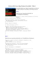
Figure 13-16: You have added text by using a new
text style.
Modifying a text style
To change a style, choose Format➪Text Style. From the Style Name drop-down list,
choose the text style you want to change. Make changes the same way you did
when creating the style. Choose Apply and then Close. AutoCAD regenerates the
drawing and changes all text that uses the style you changed. This is a powerful
way to control the look of text in your drawing.
Unfortunately, only changes to the font and text style affect current text. Other
changes, such as width factor, oblique angle, orientation, and height, are ignored.
However, new text takes on these other changes.
Note
16 539922 ch13.qxd 5/2/03 9:37 AM Page 354
355
Chapter 13 ✦ Creating Text
To change existing text to another text style, choose Properties from Standard tool-
bar and select the text. In the Properties palette, choose a new text style in the Text
Style drop-down list.
Making a style current or changing a text
object’s style
You can choose the current style when you use one of the text commands. If you
use DTEXT or TEXT, AutoCAD displays the
Specify start point of text or
[Justify/Style]:
prompt. Right-click and choose Style. (AutoCAD displays the
current style and height before the prompt.) If you know the name of the style you
want to use, type it and press Enter. AutoCAD repeats the
Specify start point
of text or [Justify/Style]:
prompt. You can choose the Justify option or
pick a start point to continue the command.
The new Styles toolbar makes is easier to make a style current or change the text
style of existing text. To make a style current, choose the style from the Text Style
Control drop-down list. To change the text style of existing text, select the text and
choose a new style from the list.
If you use MTEXT, the Multiline Editor opens, as explained in the next section.
Choose the text style you want from the Style drop-down list.
Importing a text style
As explained in Chapter 11, you can use the DesignCenter to import features from
other drawings. To import a text style, follow these steps:
1. Choose DesignCenter from the Standard toolbar to open the DesignCenter.
2. In the left pane, navigate to the drawing that has the text style you want.
3. Double-click the drawing icon or click its plus sign.
4. To see the list of the text styles, double-click the text styles icon in either the
left or right pane.
5. Double-click the text style’s icon to import it into your drawing.
6. Click the DesignCenter’s Close button to close the DesignCenter.
The drawing used in the following Step-by-Step exercise on changing text styles,
ab13-3.dwg, is in the Results folder of the AutoCAD 2004 Bible CD-ROM.
Step-by-Step: Modifying Text Styles
1. If you have ab13-03.dwg open from the previous Step-by-Step exercise,
continue to use it for this exercise. Otherwise, open
ab13-03.dwg from the
Results folder of your CD-ROM.
On the
CD-ROM
New
Feature
16 539922 ch13.qxd 5/2/03 9:37 AM Page 355
356
Part II ✦ Drawing in Two Dimensions
2. Save the file as ab13-04.dwg in your AutoCAD Bible folder.
3. The note at the bottom-left corner of the drawing uses the Notes text style.
Choose Format ➪ Text Style. In the Text Style dialog box, make sure NOTES
is the style name listed, and then choose
italic.shx from the Font Name
drop-down list. Choose Apply and then Close.
4. AutoCAD regenerates the drawing and changes the text’s font.
5. Save your drawing.
Creating Multiline Text
Single-line text is awkward when you want to type quite a bit of text. The main dis-
advantage is that single-line text does not use word wrap, a feature that wraps text
to the next line to keep a neat right margin. Multiline text (also called paragraph
text and not to be confused with multilines) solves this problem and also offers
many more formatting options compared to single-line text. The entire paragraph of
multiline text is one object.
AutoCAD 2004 introduces a new frameless Multiline Text editor. New features
include tabs and indenting. Many of the features that were previously on tabs in
the Multiline Text Editor are now available from a shortcut menu that you access
by right-clicking anywhere in the text area.
The Multiline Text Editor that you use to create multiline text resembles Windows
word processors. You use this box both to create and also to edit text and its
properties.
Using the Multiline Text Editor
To create paragraph text, choose Multiline Text from the Draw toolbar. This
starts the MTEXT command. AutoCAD tells you the current style and text
height. For example:
Current text style: ROMANS. Text height: 4 1/2"
AutoCAD continues with the Specify first corner: prompt. Specify one corner
of a bounding box to specify where to place the text. At the
Specify opposite
corner or [Height/Justify/Line spacing/Rotation/Style/Width]:
prompt,
specify the diagonally opposite corner of the bounding box. You can also choose one
of the other options to specify the text properties before you type in the text. Some
of these options are also available in the Multiline Text Editor, which opens after you
have specified the bounding box. Figure 13-17 shows the Multiline Text Editor.
When you specify the corners of the Mtext box, you see sample text at the cursor
to give you an idea of the actual current height of the text. You can change the
sample text with the new MTJIGSTRING system variable.
New
Feature
New
Feature
16 539922 ch13.qxd 5/2/03 9:37 AM Page 356
357
Chapter 13 ✦ Creating Text
Figure 13-17: The Multiline Text Editor
Type your text in the large edit box. The Multiline Text Editor wraps the text to the
next line when AutoCAD senses that the text has met the right side of the bounding
box you specified. Although you have created a bounding box with four sides,
AutoCAD only limits the text by the paragraph width, that is, the left and right
margins. If you type too much text for the bounding box, AutoCAD expands the
Text Editor.
When you type, the text may be enlarged or reduced in size. This can be discon-
certing, but when you close the editor, the text takes on the correct size. To stop
the text from resizing and the MText Editor from floating, set the MTEXTFIXED sys-
tem variable to 1.
To format selected or new text, use the buttons on the Multiline Editor’s toolbar:
✦ Style: Choose any text style from the Style drop-down box.
✦ Font: Choose any font from the Font from the drop-down list.
✦ Text Height: Choose a height from the drop-down list or type a new height in
the Text Height box.
✦ Bold: If Bold is supported for the font, select text and click Bold.
✦ Italic: If Italic is supported for the font, select text and click Italic.
✦ Underline: Select text and click Underline.
✦ Undo: Undoes recent editing operations.
✦ Redo: Redoes recent editing operations.
✦ Stack/Unstack: Toggles stacking and unstacking fractions. Use this option to
stack characters that are not numerals and not immediately before or after
the three AutoStack symbols (slash, pound sign, and carat). Select the text
and click Stack/Unstack. See the next section for more details.
✦ Color: Choose ByLayer or any color from the Color drop-down box. To choose
from additional colors, choose Select Color to open the Select Color dialog
box. (See Chapter 11 for details on using this dialog box.)
Note
16 539922 ch13.qxd 5/2/03 9:37 AM Page 357
358
Part II ✦ Drawing in Two Dimensions
To create an exponent (or superscript), type a number and then a carat, as in 2^.
Select the number and the carat and click the Stack/Unstack button. To create a
subscript, type a carat, and then the number, as in ^2, and stack it.
Right-click in the editor to display the shortcut menu. The shortcut menu contains
many important controls that are no longer available elsewhere. You have the fol-
lowing options:
✦ Undo: Undoes the last Mtext edit.
✦ Redo: Redoes the last undo operation.
✦ Cut: Places selected text in the Windows clipboard and removes it from the
editor.
✦ Copy: Place selected text in the Windows clipboard.
✦ Paste: Places text from the Windows clipboard.
✦ Indents and Tabs: Opens the Indents and Tabs dialog box, as shown in
Figure 13-18. You can set the following:
• First line indentation: Sets the indentation for the first line of the
paragraph.
• Paragraph indentation: Sets the indentation for every line of the para-
graph except the first line. Use this indentation for creating bulleted and
numbered lists.
To indent an entire paragraph, use both first line and paragraph indentation.
• Tabs: Type the location of each tab.
It’s easier to set indentation and tabs on the Multiline Editor’s ruler than in the dia-
log box. Drag the first line indent marker (the top triangle at the left of the ruler) or
the paragraph indent marker (the bottom triangle) to the left or right. To set a tab,
click on the ruler where you want the tab. To delete a tab, drag a tab marker off the
ruler.
Figure 13-18: Use the new Indents and
Tabs dialog box to set indents and tabs
for your text.
Tip
Tip
Tip
16 539922 ch13.qxd 5/2/03 9:37 AM Page 358
359
Chapter 13 ✦ Creating Text
✦ Justification: Choose a justification from the submenu. The justifications are
discussed in the “Justifying single-line text” section earlier in this chapter.
✦ Find and Replace: Opens the Replace dialog box so that you can find or
replace specified text. If you want the search to match the case of the speci-
fied text, choose Match Case. If you want the search restricted to whole words
that match the specified text, choose Whole Words. To find text, ignore the
Replace text box. To both find and replace text, enter text in both boxes. Make
sure that the cursor is at the beginning of the text if you want to search the
entire Mtext object.
✦ Select All: Selects all the text.
✦ Remove Formatting: Removes formatting, such as bold and italic. Does not
remove color or font changes.
✦ Combine Paragraphs: Combines separate paragraphs into one. First select
the paragraphs that you want to combine.
✦ Change Case: Changes the case of selected text to uppercase or lowercase.
✦ AutoCAPS: Automatically changes newly typed and imported text to upper-
case, even if the Caps Lock key is not on. (And it’s a cute pun on AutoCAD.)
✦ Symbol: Inserts the degree, plus/minus, or diameter symbol. You can also
insert a non-breaking space. Or choose Other to open the Windows Character
Map to choose any of the available symbols. Click a symbol, and then click
Select. Click Copy and then click the Close button to close the Windows
Character Map. In the Text Editor, press Ctrl+V to paste in the symbol.
✦ Import Text: Opens the Select File dialog box, which lets you choose a text
(
.txt) or Rich Text Format (.rtf) file to import. Find the file, choose it, and
click Open. AutoCAD inserts it into the Multiline Text Editor. The maximum
file size is 16 kilobytes. Other techniques for importing text are covered later
in this chapter.
Rich Text Format preserves formatting from application to application. Text-only
documents retain no formatting.
After you finish creating multiline text, close the editor in one of three ways:
✦ Click OK on the Text Formatting bar
✦ Click anywhere outside the Multiline Text Editor (but inside the drawing area)
✦ Press Ctrl + Enter
You can snap to the corners of the Mtext bounding box using the Node Object
Snap. (See Chapter 4 for an explanation of object snaps.)
New
Feature
Note
16 539922 ch13.qxd 5/2/03 9:37 AM Page 359
360
Part II ✦ Drawing in Two Dimensions
Creating stacked fractions automatically
You can create automatic stacked fractions and tolerances as you type, using a system sim-
ilar to those described earlier for creating special characters with DTEXT/TEXT.
You can also type unstacked fractions (as in 1/2), select the fraction text, and then click
Stack/Unstack on the Character tab. To create stacked fractions as you type, open the
Multiline Text Editor and follow these steps:
1. Type the numerator (or text that you want on top).
2. Type the character that defines the fraction format you want:
•
Type a slash (/) to create a fraction separated by a horizontal line.
•
Type a pound symbol (#) to create a fraction separated by a diagonal line.
•
Type a carat (^) to create a tolerance stack, which is like a fraction separated
by a horizontal line except that there is no horizontal line.
3. Type the denominator.
4. Type a space (or other nonnumeric character). AutoCAD opens the AutoStack
Properties dialog box.
5. Change any settings you want to change and click OK. AutoCAD creates the stacked
fraction.
To use the settings in the AutoStack Properties dialog box:
✦ Uncheck Enable AutoStacking to disable the automatic stacked fraction feature.
✦ Uncheck Remove leading blank if you want to retain a space between whole
numbers and fractions.
✦ Choose whether you want the slash to result in a fraction with a horizontal line or a
fraction with a slash. This choice has no effect on how the pound sign and carat work.
If you want the slash to result in a fraction with a slash (which would seem to make
more sense), you have no automatic way to create a fraction with a horizontal line.
✦ Check Don’t show this dialog again; always use these settings to stop
the dialog box from opening when you create automatic stacked fractions.
✦ Click OK to create the stacked fraction or Cancel to leave the numbers as you typed
them.
AutoStack only works with numerals immediately before and after the slash, pound sign,
and carat.
You can also set the properties of individual stacked fractions. Right-click the fraction in the
Multiline Text Editor and choose Properties from the menu. In the Stack Properties dialog
box you can change the following properties:
✦ Text: Edit the upper and lower text.
✦ Style: Change the fraction style. (See the sidebar figure for the three possible styles.)
16 539922 ch13.qxd 5/2/03 9:37 AM Page 360
361
Chapter 13 ✦ Creating Text
Specifying and changing line spacing
You can specify the spacing between lines in multiline text. Line spacing is useful
for fitting text into a schedule or table in your drawing. To set line spacing:
1. Start the Mtext command.
2. At the
Specify first corner: prompt, pick the first corner of your
Mtext box.
3. At the next prompt,
Specify opposite corner or [Height/Justify/
Line spacing/Rotation/Style/Width]:
, choose Line spacing.
4. At the
Enter line spacing type [At least/Exactly] <Exactly>:
prompt, choose Exactly.
5. At the
Enter line spacing factor or distance <1x>: prompt, type a
number, such as 1 to specify a one unit space between lines of text. (If you
type 1x, you get single line spacing, which varies according to the size of
the text.)
6. Then continue with the command.
This setting persists for future Mtext objects. To change existing line spacing, select
(but do not double-click) the multiline text. Open the Properties palette and set one
or more of the following:
✦ Line space factor: Specifies line spacing as a multiple of lines. Single line
spacing is 1.0000; double line spacing is 2.0000.
✦ Line space distance: Specifies line spacing in units. Use this measurement
(along with a line space style of Exactly) to fit text into an existing table or
schedule.
✦ Position: Position the fraction so that the top, center, or bottom is aligned with
other text.
✦ Size: Change the size of the numbers that make up the fraction. Fraction numbers
are usually smaller than regular numbers.
Typed as 3/5
Typed as 3#5
Typed as 3^5
16 539922 ch13.qxd 5/2/03 9:37 AM Page 361
362
Part II ✦ Drawing in Two Dimensions
✦ Line space style: Choose At Least (the default) to adjust line spacing based on
the height of the largest charter in the line of text. Choose Exactly to specify
line spacing that is the same regardless of differences in character height.
Specifying and changing width and rotation
To change the width of an Mtext object, you can use its grips:
1. Select the Mtext object.
2. Click one of the grips that you want to stretch to make it “hot.” (For instructions
on using grips to edit objects, see Chapter 10.)
3. At the
Specify stretch point or [Base point/Copy/Undo/eXit]:
prompt, pick a new location for the grip, to make the multiline text wider or
narrower.
You can use the Properties palette to change the width and height. You can specify
the exact width when creating the Mtext object by using the Width option after you
specify the first corner of the Mtext box. Otherwise, you generally specify the width
by picking the two corners of the Mtext box.
When the Multiline Text Editor is open, you can change the width of the Mtext
object by dragging on the right edge of the ruler. You can also change the width of
the editor itself by dragging on the right edge of the editor box.
To rotate an existing Mtext object, use the Properties palette or use the grips:
1. Select the Mtext object.
2. Click one of the grips to make it “hot.”
3. Right-click and choose Rotate.
4. At the
Specify rotation angle or [Base point/Copy/Undo/Reference/
eXit]:
prompt, pick a new location for the grip or type a rotation angle.
You can also specify the rotation while creating the Mtext object. Use the Rotate
option that appears on the command line after you specify the first corner.
Editing paragraph text
To edit paragraph text, double-click the text to open the Multiline Text Editor.
If you choose single-line text created with TEXT or DTEXT, AutoCAD opens the Edit
Text dialog box (refer to Figure 13-7).
Make your changes in the edit box. The techniques are similar to those in any word
processor. Your options are:
Note
Tip
16 539922 ch13.qxd 5/2/03 9:37 AM Page 362
363
Chapter 13 ✦ Creating Text
✦ Select text and press Del to delete the text or type to replace the selected text.
✦ Click to move the insertion point to where you want to insert text and start
typing. (To type over text, press Insert to enter overtype mode.)
✦ Use the toolbar or shortcut menu to change formatting.
To change characters, you must first highlight the characters. This lets you make
height or font changes to individual words or even letters. When changing proper-
ties that affect the entire paragraph, such as justification, you do not first highlight
the characters.
Mmt combines two MText objects into one MText paragraph. Look in \Software\
Ch13\Mmt.
Importing text
As mentioned earlier, you can import text from the Multiline Text Editor. You can
import text in three other ways:
✦ You can use drag-and-drop to insert text into a drawing. Open Windows
Explorer and locate the file. It should be a text (
.txt) or Rich Text Format
(
.rtf) file. Position the Explorer window so that you can see the file name
and your AutoCAD drawing at the same time. Click the file and drag it to your
drawing. Close Windows Explorer and move the text to the desired location.
✦ You can copy text from another file to the Windows clipboard. Open the
other file, select the text, and choose Copy from the Standard toolbar. Return
to your drawing by clicking the AutoCAD button on the Windows Taskbar.
Choose Paste from the Standard toolbar. The OLE Properties dialog box
opens (by default). Specify the properties of the object and click OK.
✦ If you are in the Multiline Text Editor, you can paste the text directly into the
editor. Right-click in the editor and choose Paste (or use Ctrl+V). You can then
format the text.
For more information on importing text, see Chapter 27.
The files used in the following Step-by-Step exercise on creating multiline text,
ab13-c.dwg and ab13.txt, are in the Drawings folder of the AutoCAD 2004
Bible CD-ROM.
Step-by-Step: Creating Multiline Text
1. Open ab13-c.dwg from your CD-ROM.
2. Save the file as
ab13-05.dwg in your AutoCAD Bible folder. This is a plat
drawing, as shown in Figure 13-19.
On the
CD-ROM
Cross-
Reference
On the
CD-ROM
16 539922 ch13.qxd 5/2/03 9:37 AM Page 363
364
Part II ✦ Drawing in Two Dimensions
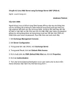
Figure 13-19: The plat drawing
Thanks to Bill Maidment of Cantech, Inc., Fairfield, Iowa for this drawing.
3. Choose Multiline Text from the Draw toolbar. At the prompts, pick points 1
and 2 in Figure 13-19. The Multiline Text Editor opens. In the Text Height box,
change the height to 12.5. In the main editing box, type the following:
Containing 108.33 acres including 5.97 acres existing R.O.W. and 4.56 acres
proposed R.O.W.
4. Highlight the text 108.33 and click Underline. Right-click in the text window
and choose Justification ➪ Middle Left. Click OK AutoCAD places the text.
5. Do a Zoom Window around the table at the lower-right corner of the drawing,
so that the table takes up about half the drawing area. Start the MTEXT com-
mand. Follow the prompts:
Specify first corner: Pick 4 in Figure 13-19.
Specify opposite corner or [Height/Justify/Line
spacing/Rotation/Style/Width]: Right-click and choose Height.
Specify height <10>: 60 ↵
Specify opposite corner or [Height/Justify/Line
spacing/Rotation/Style/Width]: Right-click and choose Line
spacing.
Enter line spacing type [At least/Exactly] <At least>: Right-
click and choose Exactly.
Enter line spacing factor or distance <1x>: 100 ↵
Specify opposite corner or [Height/Justify/Line
spacing/Rotation/Style/Width]: Pick
5 in Figure 13-19.
The Multiline Editor opens. Depending on your zoom, the text cursor may be
larger or smaller than the rows of the table, which is okay.
5
4
3
2
1
16 539922 ch13.qxd 5/2/03 9:37 AM Page 364
365
Chapter 13 ✦ Creating Text
6. If necessary, drag the right and bottom edges of the editor’s text area to
approximately match the size of the table. You may also need to drag the
right side of the ruler itself to match the width of the table. At the tab line just
to the right of the vertical line of the second column, click in the ruler to add a
tab. You see a small “L” to indicate a tab at this location.
7. Click at the left of the first line. Type the following table, pressing the Tab key
to move from column to column and pressing Enter at the end of each line.
Use the Spacebar before the acre figures in the last three rows to line up the
numbers.
1 22.93
2 2.85
3 1.51
4 1.38
8. Click anywhere outside the Multiline Text Editor to close the editor and see
the results. The text should be lined up in the table. Choose Zoom Previous to
see the entire drawing again.
9. Open Windows Explorer (Usually Start ➪ Programs ➪ Windows Explorer).
Find
ab13.txt on your CD-ROM. Move the Windows Explorer window so that
you can see both
ab13.txt and your AutoCAD screen. Drag ab13.txt from
the Windows Explorer window to 3 in Figure 13-19. If necessary, pick a grip,
press the Spacebar once to choose the Move option and click at the proper
location.
10. Select the text and open the Properties palette. (Click Properties on the
Standard toolbar.) Next to the Width item, type 500 ↵. Next to the Height item,
type 12.5 ↵.
11. Use ZOOM Window to zoom in on the new text. You can see how
%%d became
the degree symbol. This text was originally single-line text in an older
AutoCAD drawing. You can see why you wouldn’t want to retype it!
12. Choose Zoom Previous on the Standard toolbar to return to your original
view. Save your drawing.
Managing Text
Text is a complex object type. Text greatly increases drawing size and adds redraw
and regeneration time. The more complex fonts, such as the TrueType fonts, can
have a huge impact on how long it takes to open and save a file. The three tech-
niques described in this section help you to manage text and improve performance
while editing your drawing. The last section introduces a way to control the mirror-
ing of text objects.
16 539922 ch13.qxd 5/2/03 9:37 AM Page 365
366
Part II ✦ Drawing in Two Dimensions
When you draw in three dimensions, you need to figure out how to combine
three-dimensional models with two-dimensional text. You can use the HIDETEXT
system variable to choose whether you want text to act like a 3D or a 2D object.
Use the On setting, the default, if you want text to be hidden behind other objects
and to hide other objects when you use the HIDE command, such as other 3D
objects. If you use the Off setting, text will not hide other objects, or be hidden,
unless it has a thickness. (See Chapter 21 for more on the HIDE command and
adding a thickness to objects.)
Using Quicktext
The QTEXT command replaces all text with rectangles that approximate the
placement of the original text, as shown in Figure 13-20. All text objects, including
dimensions, attributes, and tolerances, are affected. To use QTEXT, type qtext ↵ on
the command line. Type on ↵ to get the rectangles; Type off ↵ to return to regular
text. Then type regen ↵ at the command line. Quicktext takes effect only after a
regeneration. It does not apply to OLE objects that you have pasted into a drawing
from the Windows clipboard. (See Chapter 27.)
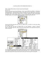
Figure 13-20: A drawing with QTEXT on. Rectangles have
replaced all the text.
Thanks to Rod Greer of R. G. Greer Design, Inc., Fergus, Ontario for this drawing.
Using AutoCAD fonts
AutoCAD fonts are simpler than TrueType fonts, and some AutoCAD fonts are
simpler than others. The simplest font is
txt.shx, the font used by the default
Standard text style. You can easily define a text style using an AutoCAD font and
Tip
16 539922 ch13.qxd 5/2/03 9:37 AM Page 366
367
Chapter 13 ✦ Creating Text
then change the font to something nicer just before plotting. AutoCAD immediately
changes the font of all text using that style. Be aware that the text may take up
more or less space than before.
When AutoCAD cannot find the specified font, it uses an alternate font. This may
happen if you receive a drawing done by someone else that uses a custom or third-
party font that you don’t have. You can specify the alternate font by choosing
Tools➪ Options and clicking the plus sign next to Text Editor, Dictionary, and Font
File Names on the Files tab. Choose Alternate Font File to specify the alternate font,
which is
simplex.shx by default.
You can further control the fonts used by AutoCAD by customizing the Font
Mapping File,
\acad.fmp. The format is current_font; font_to_substitute. You
need to use the actual file names of the fonts. To substitute a simpler font for the
Arial Black font, you could add the following line:
Ariblk.ttf;simplex.shx
To find the Windows TrueType fonts, look in the Fonts subfolder of your Windows
folder.
To find acad.fmp, choose Tools➪ Options and click the File tab. Double-click Text
Editor, Dictionary, and Font File Names. Double-click Font Mapping File. Click the
path list to view the location of acad.fmp. AutoCAD only reads the font-mapping
file when it opens a new drawing, so that any changes you make are effective only
after you start a new drawing.
Freezing text layers
Freezing text layers can help regeneration time dramatically —a good reason to
give text its own layer. Don’t forget to freeze dimension text, too. Dimensions are
usually placed on a separate layer (see Chapter 14).
Using MIRRTEXT
When you mirror sections of your drawing that include text, you usually don’t want
backward text (unless you are Alice going through the looking glass). The MIRRTEXT
system variable controls whether text is mirrored or retains its normal orientation.
The default value for MIRRTEXT is now off, so that mirrored text is not backward.
The text is copied to the mirrored location, but reads from left to right (if that is the
direction of the language you are using).
New
Feature
Note
16 539922 ch13.qxd 5/2/03 9:37 AM Page 367
368
Part II ✦ Drawing in Two Dimensions
If you do want to mirror the text, type mirrtext ↵. At the New value for
MIRRTEXT <0>:
prompt, type 1 ↵ to turn MIRRTEXT on. This system variable is
saved with the drawing, so that you may still need to change it when you open
older drawings.
The drawing used in the following Step-by-Step exercise on managing text, ab13-d.
dwg, is in the Drawings folder of the AutoCAD 2004 Bible CD-ROM.
Step-by-Step: Managing Text
1. Open ab13-d.dwg from your CD-ROM.
2. Save the file as
ab13-06.dwg in your AutoCAD Bible folder. This is a small
section of an electrical schematic, as shown in Figure 13-21. Make sure
ORTHO and OSNAP are on and set running snaps for endpoint, midpoint, and
intersection.
Figure 13-21: A section of an
electrical schematic
3. Type qtext ↵. At the Enter mode [ON/OFF] <OFF>: prompt, type on_↵.
Type regen ↵. AutoCAD replaces the text with rectangles.
4. Type qtext ↵. At the
Enter mode [ON/OFF] <ON>: prompt, type off ↵. Type
regen ↵. AutoCAD redraws the original text.
51
3
2
On the
CD-ROM
16 539922 ch13.qxd 5/2/03 9:37 AM Page 368
369
Chapter 13 ✦ Creating Text
5. Start the MIRROR command. Follow the prompts:
Select objects: Start a window by picking 2 in Figure 13-21.
Specify opposite corner: Pick 1. Press Enter to end object
selection.
Specify first point of mirror line: Use the Midpoint running
object snap to pick the midpoint at 3.
Specify second point of mirror line: Pick any point vertical
to the first point.
Delete source objects? [Yes/No] <N>: ↵
AutoCAD mirrors the objects and the text. The text is backward.
6. Choose Undo from the Standard toolbar.
7. Type mirrtext ↵. At the
Enter new value for MIRRTEXT <1>: prompt,
type 0 ↵.
8. Repeat the mirror operation using the same instructions as in Step 5. This
time AutoCAD mirrors the objects, but the text reads properly, as shown in
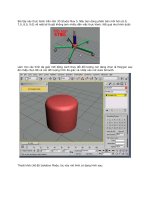
Figure 13-22.
Figure 13-22: The text on the right was
mirrored with MIRRTEXT set to 0.
9. Save your drawing.
Express Tools has a number of text routines that you may find very helpful. Table
13-3 lists these tools. See Appendix A on the CD-ROM for information on installing
Express Tools.
16 539922 ch13.qxd 5/2/03 9:37 AM Page 369
370
Part II ✦ Drawing in Two Dimensions
Table 13-3
Express Tools for Text
Command Menu Description
RTEXT Express ➪ Text➪ Displays text from an outside file. You
Remote Text can specify the text style, height, and
rotation. Use RTEDIT on the command
line to edit remote text.
TEXTFIT Express ➪ Text➪ Stretches or shrinks Text objects (but
Text Fit not MText) to fit between two points.
TEXTMASK Express ➪ Text➪ Creates a wipeout, 3D face, or 2D solid
Text Mask object behind the text with a little extra
space around the text. You can use this
to make text on top of a hatch more
legible.
TEXTUNMASK Express ➪ Text➪ Removes a text mask.
Text Unmask
TXTEXP Express ➪ Text➪ Transforms Text or Mtext into
Explode Text geometrical shapes.
TXT2MTXT Express ➪ Text➪ Converts Text objects to Mtext objects.
Convert Text to MText
ARCTEXT Express ➪ Text➪ Aligns text along an arc.
Arc-Aligned Text
TORIENT Express ➪ Text➪ Rotates multiple text, Mtext, and
Rotate Text attribute definitions to a specified angle
without moving them or aligns them so
that they are horizontal or right-side up
for easy reading.
TCIRCLE Express ➪ Text➪ Encloses selected Text or Mtext inside a
Enclose Text with Object circle, slot (a rectangle but with arcs at
each end), or a rectangle.
TCOUNT Express ➪ Text➪ Numbers lines of text by adding a prefix,
Automatic Text suffix, or overwriting the text.
Numbering
TCASE Express➪ Text➪ Offers the following ways to change
Change Text Case the case of text: uppercase, lowercase,
sentence case, title case, and toggle
case.
16 539922 ch13.qxd 5/2/03 9:37 AM Page 370
371
Chapter 13 ✦ Creating Text
Finding Text in Your Drawing
In a large, complex drawing with a lot of text, you may have difficulty finding spe-
cific text that you need to edit. The FIND command lets you find and replace text
anywhere in your drawing— not only single-line text and multiline text but also text
in block attributes, dimensions, and hyperlinks.
To use the FIND command, choose Edit➪ Find to open the Find and Replace dialog
box, as shown in Figure 13-23.
Figure 13-23: The Find and Replace
dialog box finds text anywhere in your
drawing.
Here’s how to use the Find and Replace dialog box:
1. Type the text you want to find in the Find text string text box. Use the
drop-down list to choose recently used text strings.
2. If you want to replace the text you find with new text, type it in the Replace
with text box. This box also includes a drop-down list of recently used text
strings.
3. If you want to limit or expand the scope of your search, use the Search in
drop-down box. If you selected objects before starting the FIND command,
this drop-down list displays Current selection. You can choose Entire Drawing
from this list. You can also click the Select objects button to return to your
drawing and select objects. The FIND command then limits its search to
selected objects.
4. Choose Options to specify the type of text FIND will search. By default it
searches all types of text. You can also choose the Match case and Find whole
words only options.
16 539922 ch13.qxd 5/2/03 9:37 AM Page 371
372
Part II ✦ Drawing in Two Dimensions
5. Click Find (Next) to find the next instance of the text string. The dialog box
displays the text in the context of the text around it.
6. Click Replace to replace the text string with the replacement text. Click
Replace All to replace all instances of the text string with the replacement text.
7. If the Search in drop-down list is set to Current selection, you can click Select
All to return to your drawing with all instances of the text string you have
searched for selected. AutoCAD tells you on the command line how many
objects it has selected. You can use this to delete all these objects, for example.
Also, because the objects have grips, it is easy to locate them in your
drawing —this is useful for a drawing large enough so that you can’t read the
text when you have the entire drawing displayed on your screen.
8. Use the Zoom To button to zoom in to a selection that the FIND command has
found. You can then edit the text. As with the Select All button, this feature is
useful for large drawings where the text is not legible unless you zoom in.
9. After you are finished, click Close to close the dialog box.
Checking Your Spelling
If you take pride in the accuracy of your drawings, you might as well make sure that
the text is spelled correctly. Use the SPELL command to check your spelling.
AutoCAD’s spelling checker acts just like the one in your word processor.
Choose Tools➪ Spelling and select some text objects to open the Check Spelling
dialog box, as shown in Figure 13-24. You can type all ↵ to check the spelling for the
entire drawing.
Spell checking also checks text inside blocks. See Chapter 18 for the full explanation
of blocks.
Figure 13-24: The Check Spelling
dialog box
Note
16 539922 ch13.qxd 5/2/03 9:37 AM Page 372
373
Chapter 13 ✦ Creating Text
You have the following options:
✦ Ignore: Choose Ignore to ignore the current instance of this word only.
✦ Ignore All: Choose Ignore All to ignore all instances of this word.
✦ Change: Select the suggested word you want and choose Change to change
the current instance of the word to one of the suggested words.
✦ Change All: Select the suggested word you want and choose Change All to
change all instances of the word to one of the suggested words.
✦ Add: Choose Add to add the word to the dictionary. The word will not appear
again as misspelled.
✦ Lookup: Use this if you type a word in the Suggestion text box and want to
check its spelling. AutoCAD then lists words similar to the word in the
Suggestion text box.
AutoCAD automatically moves from word to word until you see the message
Spelling Check Complete.
Strangely enough, if you don’t have any misspelled words in your drawing, you
cannot open the Check Spelling dialog box. AutoCAD simply issues the Spelling
Check Complete message. The trick is to insert a misspelled word and then use
the SPELL command. You can erase or correct the word afterward.
Customizing the spelling dictionary
You can change the main and custom spelling dictionaries. To change the spelling
dictionaries, choose Change Dictionaries from the Check Spelling dialog box to
open the Change Dictionaries dialog box, as shown in Figure 13-25.
Figure 13-25: The Change Dictionaries
dialog box
Tip
16 539922 ch13.qxd 5/2/03 9:37 AM Page 373
374
Part II ✦ Drawing in Two Dimensions
The main dictionary comes with AutoCAD and is not customizable. You can choose
from various languages depending on your version of AutoCAD. For example, my
list lets me choose from American English, British English (ise), British English
(ize), French with unaccented capitals, and French with accented capitals.
The custom spelling dictionary is the dictionary you add to when you click Add in
the Check Spelling dialog box. It is a simple text file that includes words that you
have added during spelling checks, as well as a list of AutoCAD-related words
already included by AutoCAD. To see these words, scroll down the list in the
Custom dictionary words section of the Change Dictionaries dialog box.
You can add words to the custom dictionary by typing them in the Custom dictio-
nary words text box and clicking Add. This feature lets you add a number of words
at one time.
Another way to edit the custom dictionary is to open the file directly with a text edi-
tor. The AutoCAD custom dictionary is called sample.cus. To find sample.cus,
choose Tools➪ Options and click the File tab. Double-click Text Editor, Dictionary,
and Font File Names. Double-click Custom Dictionary File. Click the path list to view
the location of sample.cus.
Figure 13-26 shows sample.cus opened in Notepad, the Windows text editor.
Figure 13-26: Opening sample.cus in
Notepad so that you can edit it directly
You can use a different custom dictionary. It can be useful, for example, to use the
same dictionary in AutoCAD as you use in your word processor. For example, here’s
how to use the Microsoft Word dictionary:
1. Find Word’s custom dictionary. If necessary, choose Start➪ Find and use the
Windows Find dialog box to find the file. It is called
custom.dic. As with the
AutoCAD custom dictionary, you can open it with Notepad and edit it directly.
2. As explained in the previous Tip, find the location of
sample.cus. Use
Windows Explorer to copy the file to that folder. You can hold down Ctrl as
you drag it from one folder to another or use the right mouse button to click
the file, choose Copy, and then paste it in its new location.
Tip
16 539922 ch13.qxd 5/2/03 9:37 AM Page 374
375
Chapter 13 ✦ Creating Text
3. Click custom.dic to highlight it. Click it again and change its file name exten-
sion to
.cus. Press Enter. (Windows asks you if you are sure you want to do
this. Click Yes.)
4. Click Change Dictionaries in the Check Spelling dialog box to open the Change
Dictionaries dialog box. In the Custom dictionary text box, type in the name of
the dictionary file, or choose Browse, find it, and click Open.
5. Click Apply & Close to return to the Check Spelling dialog box and then Cancel
to return to your drawing.
Summary
In this chapter, you learned how to create, edit, and manage text. You read about:
✦ Using DTEXT and TEXT to create single-line text
✦ Editing single-line text
✦ Scaling and justifying text without moving it
✦ Creating text styles to control the formatting of your text
✦ Utilizing MTEXT for creating and editing paragraph text, including using the
new Multiline Text Editor
✦ Importing text
✦ Managing text for fastest display
✦ Finding and replacing text and how to check spelling in your drawing
In the next chapter, you read how to create dimensions.
✦✦✦
16 539922 ch13.qxd 5/2/03 9:37 AM Page 375
16 539922 ch13.qxd 5/2/03 9:37 AM Page 376
Drawing
Dimensions
D
imensions are an important part of most AutoCAD
drawings. Dimensions indicate the measurement of the
models you have created and are used in the manufacturing
process. AutoCAD’s dimensions offer a great deal of flexibility.
In this chapter, I cover the process of drawing dimensions.
In the next chapter, I explain how to customize the format of
your dimensions by using dimension styles.
Working with AutoCAD’s
Dimensions
Dimensioning is usually done after you complete all or most of
a drawing. Dimensioning a drawing all at once lets you create
a unified, organized look for your dimensions. Before you can
dimension drawing, you need to understand the elements of a
dimension and how to prepare for dimensioning.
In Chapter 17, I explain how to dimension a drawing on a
paper space layout.
The elements of a dimension
A dimension is a complex object, containing many parts.
Understanding these parts and how they relate to the object
you are dimensioning is an important first step. Figure 14-1
shows a typical linear dimension.
Cross-
Reference
14
14
CHAPTER
✦✦✦✦
In This Chapter
Working with
AutoCAD’s
dimensions
Drawing linear and
aligned dimensions
Dimensioning arcs,
circles, and angles
Creating ordinate
dimensions
Drawing leaders
Editing dimensions
✦✦✦✦
17 539922 ch14.qxd 5/2/03 9:37 AM Page 377
378
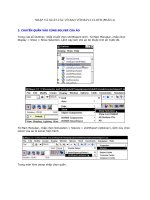
Part II ✦ Drawing in Two Dimensions
Figure 14-1: The parts of a dimension
The parts of a dimension are:
✦ Extension lines: These extend from the dimensioned object to the dimension
line and arrowheads. A small gap usually separates the dimensioned object
and the start of the extension lines. Extension lines visually clarify the extents
of the object being dimensioned.
In dimensions, the word extension (or extend) is used in two other ways besides
referring to extension lines. First, the extension line itself usually extends not only
from the object being dimensioned but past the dimension line. You can specify
the amount of this extension. Also, in architectural dimensions, the dimension line
extends past the extension lines. You can specify this extension as well.
✦ Dimension text: This tells you the actual measurement of the dimensioned
object. You can format this text in decimals, fractions, scientific units, and
so on.
✦ Dimension line: This extends between the extension lines.
✦ Arrowheads: These mark the intersection of the dimension line and the
extension lines. They can take several forms, such as tick marks, open arrows,
or dots.
Dimensions have two interesting properties that you need to understand before
you can successfully work with them.
✦ Dimensions are blocks. I have mentioned blocks before, and they are fully
covered in Chapter 18. Blocks are groups of objects that you can manipulate
as one object. As a result, if you pick a dimension, all parts of the dimension
are selected.
Note
Arrowhead
Line object
Extension line
Dimension text
Dimension line
17 539922 ch14.qxd 5/2/03 9:37 AM Page 378