AutoCAD Basics 2004 bible phần 5 pps
Bạn đang xem bản rút gọn của tài liệu. Xem và tải ngay bản đầy đủ của tài liệu tại đây (1.64 MB, 132 trang )
486
Part II ✦ Drawing in Two Dimensions
Figure 16-17: The Boundary Creation dialog box
Follow these steps:
1. The Object Type drop-down list determines the type of object BOUNDARY cre-
ates. Choose either Region or Polyline.
2. Choose the boundary set, which is the area AutoCAD analyzes to create the
boundary. Usually, you can accept the default of Current Viewport. However,
if you have a very complex drawing, choose New to temporarily return to
your drawing. Specify a window around the area you want for the boundary
set. AutoCAD returns you to the dialog box.
3. To specify the enclosed area for the boundary, choose Pick Points. AutoCAD
returns you to your drawing with the
Select internal point: prompt.
4. Pick any point inside the closed area you want for your boundary. AutoCAD
starts to think as follows:
Selecting everything Selecting everything visible
Analyzing the selected data Analyzing internal islands
5. AutoCAD then prompts you for another internal point. If you want to create
other boundaries, continue to pick internal points. Press Enter to end point
selection.
AutoCAD informs you how many regions or polylines it created and ends the
command.
By default, island detection is on. BOUNDARY detects enclosed areas that are
totally inside the boundary area and creates polylines or regions of those enclosed
areas as well.
Note
19 539922 ch16.qxd 5/2/03 9:38 AM Page 486
487
Chapter 16 ✦ Drawing Complex Objects
When BOUNDARY creates a region or polyline, the original objects are not deleted.
You end up with a region or polyline on top of your original objects.
The drawing used in the following Step-by-Step exercise on creating boundaries,
ab16-e.dwg, is in the Drawings folder of the AutoCAD 2004 Bible CD-ROM.
Step-by-Step: Creating Boundaries
1. Open ab16-e.dwg from your CD-ROM.
2. Save the file as
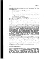
ab16-06.dwg in your AutoCAD Bible folder. This is a bushing,
shown in Figure 16-18.
Figure 16-18: A bushing
3. Choose Draw ➪ Boundary. In the Boundary Creation dialog box, choose
Region as the Object type.
4. Choose Pick Points.
5. At the
Select internal point: prompt, choose 1 in Figure 16-18.
6. Press Enter to end internal point selection. AutoCAD responds:
4 loops extracted.
4 Regions created.
BOUNDARY created 4 regions
7. To see the new region, start the MOVE command. At the Select objects:
prompt, pick 2. Move the region to the right —the exact distance is not
important. You see both the new region and the original objects.
8. Save your drawing.
2
1
On the
CD-ROM
19 539922 ch16.qxd 5/2/03 9:38 AM Page 487
488
Part II ✦ Drawing in Two Dimensions
Creating Hatches with Solid,
Gradient, or Patterned Fills
Hatches are patterns that fill in an area. Most types of drafting make use of hatch-
ing. In architectural drafting, hatched areas are used to indicate materials, such as
insulation or grass. In mechanical drafting, hatching often indicates hidden areas or
certain materials. AutoCAD provides a large number of hatch patterns. Hatches are
created from repeating patterns of lines. You can also create solid fills in the same
way you create hatch patterns.
AutoCAD 2004 introduces gradient hatch fills that fill any area with a one or two-
color gradient. You can choose from a number of gradient styles and angles.
Chapter 31 explains how to create your own hatch patterns.
Figure 16-19 shows a drawing with a simple hatch pattern. Here the cross section
shows solid metal hatched to distinguish it from the holes.
Understanding hatch patterns
Hatch patterns have two qualities that are similar to dimensions:
✦ They are blocks. This means that all the lines that fill in an area are one
object. Blocks are covered in Chapter 18.
✦ They are associative. If you edit the object that is hatched, the hatch automat-
ically adjusts to fit the new shape of the object.
Figure 16-19: Hatch patterns help you distinguish between
different materials or textures.
Thanks to Jerry Bottenfield of Clow Valve Company, Oskaloosa, Iowa, for
this drawing.
Cross-
Reference
New
Feature
19 539922 ch16.qxd 5/2/03 9:38 AM Page 488
489
Chapter 16 ✦ Drawing Complex Objects
You have several ways to specify exactly what area you want to hatch. In order to
properly hatch an area, AutoCAD tries to find closed boundaries. Often, the key to
successful hatching lies in how you construct the area you want to hatch. You can
use the BOUNDARY and REGION commands covered in previous sections of this
chapter to create complex closed areas that AutoCAD can easily find and hatch.
AutoCAD stores hatch pattern definitions in the
acad.pat file. If you create your own
hatch patterns, you can put them in another file with the file name extension
.pat.
Create a separate layer for hatch patterns. You may want to turn off or freeze your
hatch layer to reduce visual clutter or assist in selecting objects. Hatches are also
typically a different color than the model you are hatching.
Defining a hatch
To hatch an area, choose Hatch from the Draw toolbar. This starts the
BHATCH command. AutoCAD opens the Boundary Hatch and Fill dialog box,
shown in Figure 16-20.
Figure 16-20: The Boundary Hatch and Fill dialog
box with the Hatch tab on top
Use this dialog box to define your hatch. From the Type drop-down box, choose one
of the three options:
✦ Predefined: Enables you to select one of AutoCAD’s hatch patterns.
✦ User-defined: Enables you to define your own hatch pattern by specifying the
angle and spacing, using the current linetype.
✦ Custom: Enables you to choose a pattern you have created in your own
.pat file.
Tip
19 539922 ch16.qxd 5/2/03 9:38 AM Page 489
490
Part II ✦ Drawing in Two Dimensions
Click the Pattern drop-down box to choose the hatch patterns from a list. Or click
the box marked with an ellipsis to open the Hatch Pattern Palette and choose from
the image tiles, as shown in Figure 16-21.
Figure 16-21: The Hatch Pattern Palette,
shown with the Other Predefined tab
on top
In the palette, click the tabs to see the different types of hatches. Click the image
tile to choose a hatch pattern and click OK. The palette is simply another method of
choosing the hatch pattern —you can also choose the pattern by using the Pattern
drop-down list. The swatch shows you how your chosen hatch will look.
You can also insert hatches from the tools palette. See Chapter 26 for a description
of the tools palette.
The Custom pattern drop-down box is available only if you have chosen Custom as
the pattern type. Here you choose the name of your custom hatch pattern.
Use the Angle text box to rotate the angle of the hatch pattern. You can choose
from the drop-down list or type an angle. Watch out here —many of the patterns
are already defined at an angle. The hatch pattern in Figure 16-22 uses a 0-degree
angle because ANSI31 is defined as diagonal lines.
The Scale box determines the scale of the hatch pattern. You can choose from the
drop-down list or type a scale. AutoCAD scales the hatch pattern proportionately to
its definition. A scale of 1 (the default) creates the hatch as defined. A scale of 0.5
shrinks it by one-half. Figure 16-22 shows two hatch patterns using the ANSI31 pat-
tern. The left one uses a scale of 1, and the right one uses a scale of 0.5.
Cross-
Reference
19 539922 ch16.qxd 5/2/03 9:38 AM Page 490
491
Chapter 16 ✦ Drawing Complex Objects
Figure 16-22: You can scale the hatch pattern to your needs.
The Spacing box and the Double check box are available if you choose a user-defined
hatch pattern. A user-defined hatch uses the current linetype and creates a hatch
based on the spacing and angle you specify. Figure 16-23 shows a user-defined double
hatch with an angle of 45 degrees and 0.1 unit spacing.
Figure 16-23: A user-defined hatch
To define a user-defined hatch pattern:
1. Choose Hatch from the Draw toolbar to open the Boundary Hatch and Fill
dialog box.
2. In the Type drop-down box, choose User-defined.
Scale = 1
Scale = 5
19 539922 ch16.qxd 5/2/03 9:38 AM Page 491
492
Part II ✦ Drawing in Two Dimensions
3. In the Angle box, type an angle or choose one from the drop-down list. When
creating a user-defined hatch, you need to specify the actual angle that you
want to see.
4. In the Spacing box, enter the spacing between the lines. If you type .5,
AutoCAD creates a hatch pattern with lines 0.5 units apart.
5. If you want to cross-hatch so that the parallel lines are crossed by an equal
number of perpendicular lines, check Double.
The ISO pen width box is available only for ISO predefined hatch patterns. AutoCAD
adjusts the scale of the pattern according to the pen width you specify. When you
choose a pen width from the drop-down box, the scale shown in the Scale box auto-
matically changes to be equal to the pen width. Note that you still have to separately
set the width of your plotter pens when you plot your drawing.
In the next section I explain how to place the hatch.
The Express Tools SUPERHATCH command creates a hatch pattern from an image,
block, xref, or wipeout. Choose Express ➪ Draw ➪ Super Hatch. For information on
installing Express Tools, see Appendix A on the CD-ROM.
Determining the hatch boundary
The hardest part of hatching is placing the hatch, not defining it. Hatching an entire
object is the simplest way to place a hatch. But often the area you want to hatch is
fairly complex, and AutoCAD needs to do some calculations to determine it.
The Boundary Hatch and Fill dialog box offers two ways to specify the hatch bound-
ary— you can pick points inside an area and let AutoCAD try to find an enclosed
boundary, or you can select objects. If you want to hatch an entire object:
1. Choose Select Objects. AutoCAD returns you temporarily to your drawing.
2. Select all the objects you want to hatch. You can use all the standard object
selection options to select objects. Remove and Add are especially helpful.
3. Press Enter to end object selection and return to the dialog box.
If the area you want to hatch does not neatly fit into one or more objects, choose
Pick Points. AutoCAD handles this task in the same way it handles the BOUNDARY
command, also covered in this chapter. AutoCAD temporarily returns you to your
drawing and displays the following:
Select internal point: Selecting everything
Selecting everything visible
Analyzing the selected data
Select internal point:
New
Feature
19 539922 ch16.qxd 5/2/03 9:38 AM Page 492
493
Chapter 16 ✦ Drawing Complex Objects
AutoCAD is determining the boundary set, which is simply everything visible on the
screen. At the
Select internal point: prompt, pick a point that is inside the
boundary that you want to hatch. You can continue to pick internal points to hatch
adjoining areas. AutoCAD helpfully highlights the boundaries it finds. Press Enter to
return to the dialog box.
While you are in your drawing, either before or after picking points or selecting
objects, you can right-click to open a very useful shortcut menu.
Choose from the following options on the shortcut menu:
✦ Enter: Returns you to the dialog box.
✦ Undo Last Select/Pick: Undoes your most recent object selection or point pick.
✦ Clear All: Undoes all your picks/object selections.
✦ Pick Internal Point: Switches to picking of internal points.
✦ Select Objects: Switches to selection of objects.
✦ Normal Island Detection: Sets island detection to normal mode.
✦ Outer Island Detection: Sets island detection to outer mode.
✦ Ignore Island Detection: Sets island detection to ignore mode.
✦ Preview: Previews the hatch.
This shortcut menu enables you to manage the hatch boundary without returning
to the dialog box. Previewing the hatch before applying it is always a good idea.
After previewing a hatch, right-click or press Enter to accept the preview and place
the hatch. Press Esc or left-click to return to the Boundary Hatch and Fill dialog box.
Click OK to create the hatch. AutoCAD creates the hatch and closes the dialog box.
The dialog box has several other options:
✦ Click Preview if you want to try it before you apply it.
✦ Click View Selection if you want to temporarily return to your drawing and
check which objects you have selected.
✦ Choose Inherit Properties to use the hatch type, pattern, angle, scale, and/or
spacing of an existing hatch. AutoCAD returns you to your drawing, and you
pick a hatch pattern. You then return to the Boundary Hatch and Fill dialog box.
✦ Click Nonassociative if you want to create a hatch that is not associated with
its object.
The Remove Islands option is discussed in the next section.
New
Feature
Tip
19 539922 ch16.qxd 5/2/03 9:38 AM Page 493
494
Part II ✦ Drawing in Two Dimensions
Islands
Islands are enclosed areas entirely inside a hatch boundary. Islands make hatching
more difficult because sometimes you don’t want to hatch the inside of the island.
Figure 16-24 shows a top view of a 3-inch operating nut, which is a good example of
enclosed areas with islands.
Text is counted as an island, enabling you to hatch areas that contain text without
hatching over the words.
Figure 16-24: A model that includes
islands can be more challenging
to hatch.
Thanks to Jerry Bottenfield of Clow Valve
Company, Oskaloosa, Iowa, for this drawing.
Managing islands when you select objects to hatch
When you choose the hatching boundary by selecting objects, you must also select
the islands. If you can select the entire area by window, you automatically include
the internal islands. If you need to pick individual objects, you must also pick the
islands individually. If you later erase an island, AutoCAD retains hatch associativity
and regenerates the hatch so it covers the entire outer boundary.
The resulting hatch depends on the boundary style. To specify the boundary
style, in the Boundary Hatch and Fill dialog box, click the Advanced tab, shown
in Figure 16-25.
Note
19 539922 ch16.qxd 5/2/03 9:38 AM Page 494
495
Chapter 16 ✦ Drawing Complex Objects
Figure 16-25: The Advanced tab is used to refine
the hatching process.
Three boundary styles affect how islands are hatched:
✦ Normal: Hatches alternating areas so that the outer area is hatched, the next
inner island is not hatched, the next inner island is hatched, and so on.
✦ Outer: Hatches only the outer area and does not hatch any inner islands.
✦ Ignore: Ignores islands and hatches everything from the outside in.
Figure 16-26 shows three copies of the nut hatched in the three styles. To hatch this
model, I selected the entire model, except the spout at the bottom, with a window.
Figure 16-26: Hatching islands using the three boundary styles
Outer
Normal
Ignore
19 539922 ch16.qxd 5/2/03 9:38 AM Page 495
496
Part II ✦ Drawing in Two Dimensions
Managing islands when you pick points to specify the hatch
When you pick points instead of selecting objects, you do not need to select the
islands. AutoCAD detects islands by default. As soon as you pick points, the Remove
Islands button becomes available, and you can select the islands to remove them
from consideration. For example, if you remove all the islands shown in Figure 16-26,
the result is the same as using the Ignore style — everything inside the outside
boundary is hatched.
Other advanced options
On the Advanced tab you can also specify a smaller boundary set than the objects
visible on-screen. Use this only when you are picking points and have such a com-
plex drawing that AutoCAD takes a long time to analyze the visible objects.
When you pick points to determine the hatch boundary, AutoCAD uses the same
mechanism as the BOUNDARY command to temporarily create a boundary for
hatching. Check Retain Boundaries on the Advanced tab if you want to draw the
boundary as an object and specify if you want it to be a region or a polyline.
Otherwise, AutoCAD discards the boundary once it completes the hatch. For more
information, see the discussion of the BOUNDARY command earlier in this chapter.
You can choose whether you want to include islands in the boundaries that AutoCAD
creates by choosing the Island detection method. The Flood method includes islands
as boundary objects. The Ray casting method excludes islands as boundary objects.
Dragging and dropping hatch patterns
You can open a .pat (hatch pattern) file from the DesignCenter, preview its hatch
patterns, and drag any hatch pattern into any closed object in your current drawing.
Here’s how to drag a hatch pattern from the DesignCenter:
1. Click DesignCenter on the Standard toolbar (or press Ctrl+2) to open the
DesignCenter.
2. Use the Tree View to navigate to the folder that contains your
acad.pat or
other
.pat file. If necessary, click the Desktop button and navigate from there.
To find the location of your .pat files, choose Tools ➪ Options and click the File tab.
Double-click the Support File Search Path option. One of the paths listed contains
your hatch files.
3. Double-click the folder and select a hatch pattern (.pat) file. The main hatch
pattern file is
acad.pat. (Of course, if the .pat file that you want is in another
location, navigate accordingly.)
4. On the right pane of the DesignCenter, drag the hatch pattern that you want
onto a closed object in your drawing. If you need more options, right-click the
pattern and choose BHATCH to open the Boundary Hatch and Fill dialog box
and specify the hatch parameters in the usual way.
Note
19 539922 ch16.qxd 5/2/03 9:38 AM Page 496
497
Chapter 16 ✦ Drawing Complex Objects
Creating gradient fills
Gradient fills are a new feature for AutoCAD 2004. Gradients are fills that gradually
change from dark to light or from one color to another. Use gradients to create pre-
sentation-quality illustrations without rendering. You can use gradients as a substi-
tute for shading because it offers more flexible options. To create a gradient:
1. Choose Hatch from the Draw toolbar to open the Boundary Hatch and Fill
dialog box.
2. Click the Gradient tab, shown in Figure 16-27.
Figure 16-27: Use the Gradient tab of the Boundary
Hatch and Fill dialog box to create gradient fills of
closed objects.
3. Choose One Color or Two Color.
• If you choose One Color, click the ellipsis button to the right of the color
swatch to open the Select Color dialog box, where you can choose the color
you want. (For instructions on using this dialog box, see Chapter 11.) Then
use the Shade/Tint slider to choose if you want the gradient to range lighter
or darker. You see the result in the gradient swatches below the slider.
• If you choose Two Colors, you see two color swatches. Click each ellipsis
button and choose a color.
4. Choose one of the nine gradient styles.
5. If you want the gradient to be symmetrical, check the Centered check box.
To create a gradient that is not symmetrical, uncheck the Centered check box.
When you uncheck the Centered check box, the gradient focus moves up and
to the left. (You can change this location by changing the angle, as explained
in the next step.)
19 539922 ch16.qxd 5/2/03 9:38 AM Page 497
498
Part II ✦ Drawing in Two Dimensions
6. From the Angle drop-down list, choose an angle. If your gradient is centered,
the gradient rotates around its center and remains symmetrical. If your gradi-
ent is not centered, the gradient rotates around the edges. Watch the gradient
style tiles to see the results. You can type an angle that is not on the list.
7. Choose Pick Points to pick a location inside a closed area or choose Select
Objects to select closed objects, as explained in the section, “Determining the
hatch boundary.” (The other options are the same as for Hatches.) In your
drawing, specify the area you want to hatch and end selection to return to the
dialog box.
8. To preview the gradient, click Preview. To return to the dialog box, press Esc.
9. Click OK to finalize the hatch.
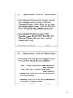
See Figure 16-28 for an example of some gradient fills. You could turn off the bound-
ary layer for a more realistic look.
When you create a gradient, it appears in front of the line of the object it fills. In
some cases, the object’s line disappears and all you see is the gradient. To move
the object to the front and display its line, select the gradient and choose Tools ➪
Display Order ➪ Send to Back or Send Under Object.
Figure 16-28: These gradients give the illusion of light shining from the left. See
Figure 8-29, which shows the original isometric drawing without the gradients.
Thanks to James Wedding for permission to use the drawing on the right from Jones & Boyd, Inc.
Editing hatches
To edit a hatch pattern including a solid or gradient, double-click it. AutoCAD opens
the Hatch Edit dialog box, shown in Figure 16-29. You can also choose Modify➪
Object ➪ Hatch and then select a hatch object.
Note
19 539922 ch16.qxd 5/2/03 9:38 AM Page 498
499
Chapter 16 ✦ Drawing Complex Objects
Figure 16-29: The Hatch Edit dialog box
As you can see, this dialog box is exactly the same as the Boundary Hatch and Fill
dialog box, except that not all of the options are available. You can use this dialog
box to change any of the hatch properties. You can change the boundary style on
the Advanced tab. You can also preview the hatch. After you make your changes,
click Apply to return to your drawing.
Because hatches are associative (unless you explode them or chose to create them
as nonassociative), when you edit their boundaries, they adjust to fit the new bound-
ary. However, if the new boundary is no longer closed, the hatch may lose its associa-
tivity. AutoCAD warns you with the
Hatch boundary associativity removed
message.
To move or stretch a hatched boundary, you can select the hatch along with the
boundary. However, perhaps you want to change the boundary’s layer. You may
find it difficult to select the boundary without the hatch, especially if the hatch is
tightly spaced. If you are at a
Select objects: prompt, use a window to select the
boundary and the hatch together, and then use the Remove selection option to pick
the hatch. Another option is to turn off the hatch’s layer. Finally, you can zoom in
enough so that you can pick the boundary without the hatch lines.
You can also edit a gradient in the Properties palette. Choose Properties on the
Standard toolbar and use the items in the Pattern section. You can change the col-
ors, angle, type, and whether or not it is centered.
When you create hatches— solid fill or lines— AutoCAD displays them if FILL is on,
which it is by default. To turn FILL off, type fill ↵ and off ↵. You must regenerate
the drawing to see the effect.
Note
New
Feature
19 539922 ch16.qxd 5/2/03 9:38 AM Page 499
500
Part II ✦ Drawing in Two Dimensions
You may find it difficult to select solid fill hatches. In some locations, you can pick
the solid hatch, while at other points you get the
Other corner: prompt, meaning
that AutoCAD didn’t find anything. Try a crossing window. If necessary, try a cross-
ing window at the edge of the hatch. This always selects the solid hatch but also
selects the boundary. Hatches have a grip at their center. If you can find the grip
and include it in the window, you can easily select the solid hatch.
The drawing used in the following Step-by-Step exercise on creating and editing
hatches, ab16-f.dwg, is in the Drawings folder of the AutoCAD 2004 Bible
CD-ROM.
Step-by-Step: Creating and Editing Hatches
1. Open ab16-f.dwg from your CD-ROM.
2. Save the file as
ab16-07.dwg in your AutoCAD Bible folder.
3. Choose Hatch from the Draw toolbar. On the Hatch tab of the Boundary
Hatch and Fill dialog box, choose ANSI35 from the Pattern drop-down list.
From the Scale drop-down list, choose 0.5. Click Select Objects.
4. AutoCAD returns you to your drawing. Pick the two large circles in Figure
16-30. Right-click and choose Preview. Press Esc to return to the dialog box.
Click OK to create the hatch and end the BHATCH command.
Figure 16-30: The result after editing the two hatches
5. Again choose Hatch from the Draw toolbar. From the Type drop-down list,
choose User-defined. Set the angle to 135 and the spacing to 0.05.
6. Choose Pick Points. In your drawing, pick points
1, 2, 3, and 4 in Figure 16-30.
Right-click and choose Preview. Right-click again to create the hatch and end
the BHATCH command.
1 2 3 4
On the
CD-ROM
19 539922 ch16.qxd 5/2/03 9:38 AM Page 500
501
Chapter 16 ✦ Drawing Complex Objects
7. Click the circumference of the left large circle. (If necessary, zoom in to avoid
selecting the hatching.) Pick the top grip to make it hot. At the
Specify
stretch point or [Base Point/Copy/Undo/eXit]:
prompt, type .35 ↵.
Press Esc to remove the grips.
8. Double-click one of the hatches at the top of the model. Notice that AutoCAD
selects all of them because they were created with one command. In the
Hatch Edit dialog box that opens, change the angle to 90 and the spacing to
0.04. Click OK. Your drawing should look like Figure 16-30.
9. Save your drawing.
Using the SOLID command
AutoCAD also has a command, SOLID, that creates solidly filled areas. (It is not at
all related to 3D solids.) In general, BHATCH is much more flexible. However,
although the SOLID command is a 2D command, it is sometimes used in 3D draw-
ing. When you create a 2D solid and give it thickness, it creates surfaces with tops
and bottoms. See Chapter 24 for a description of how to use the SOLID command
to create 3D models.
SOLID is used to create straight-edged shapes. If FILL is on, AutoCAD fills in the
shape with a solid fill (that’s why it’s called SOLID).
To draw a solid, type solid ↵. AutoCAD prompts you for first, second, third, and
fourth points. You must specify these points in zigzag order, not around the perime-
ter of the shape. After the fourth point, AutoCAD continues to prompt you for third
and fourth points, which you can use to create new adjacent solids. Press Enter to
end the command.
Creating and Editing Multilines
Multilines are sets of parallel lines that you draw with one command. You can spec-
ify how far apart they are, and each line can have its own color and linetype.
Multilines are used for drawing architectural plans where you need to draw an
inner and outer wall. To draw a multiline, you first define, save, and load a multiline
style. Then you can use the multiline style to draw multilines. There is a separate
command for editing multilines that enables you to break multiline intersections, as
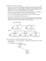
you would for the doors and windows in a floor plan. Figure 16-31 shows a floor
plan for an apartment drawn using multilines.
19 539922 ch16.qxd 5/2/03 9:38 AM Page 501
502
Part II ✦ Drawing in Two Dimensions
Figure 16-31: A floor plan of an apartment drawn
by using multilines
Thanks to Bill Wynn of New Windsor, Maryland, for this drawing.
Creating a multiline style
The first step in drawing multilines is to design the multiline style. To create a multi-
line style, choose Format ➪ Multiline Style to open the Multiline Styles dialog box, as
shown in Figure 16-32.
Figure 16-32: The Multiline Styles
dialog box
Like text styles and dimension styles, multiline styles group a set of properties under
one name. AutoCAD provides a default multiline style called Standard that defines two
lines 1 unit apart. Multiline styles have two parts: element properties and multiline
19 539922 ch16.qxd 5/2/03 9:38 AM Page 502
503
Chapter 16 ✦ Drawing Complex Objects
properties. The element properties define each individual line element. The multiline
properties define properties that apply to the multiline as a whole.
Defining element properties
To start defining the multiline style, type a new name in the Name text box and click
Add. Then choose Element Properties to open the Element Properties dialog box,
shown in Figure 16-33.
The Elements box lists the current elements of the multiline. Elements are simply
the lines that make up the multiline. The offset defines the distance of the line from
the start point when you start to draw. An offset of zero places the line on the start
point. As you can see, the Standard multiline style has two elements, each 0.5 units
from the start point. Figure 16-34 shows the Standard multiline style as it appears in
relation to the start point you pick.
Figure 16-33: The Element Properties
dialog box
Figure 16-34: The Standard multiline
style places two lines on either side of
the start point.
You can also change the relationship of the start point and the element lines by
using the Justification option when you draw the multiline, as explained later, in
the “Drawing multilines” section.
Note
First element
Start point
.5 units
Second element
19 539922 ch16.qxd 5/2/03 9:38 AM Page 503
504
Part II ✦ Drawing in Two Dimensions
To define the element lines of a multiline style, follow these steps:
1. In the Elements box, highlight the first element. Even if you typed a new
name for the multiline style, the elements listed are the same as the current
multiline style.
When creating a new multiline style, first set as current the multiline style that is
the most similar to the one you want to create.
2. In the Offset box, type the offset you want. The offset should be zero if you
want the line to appear on your pick points, a positive number (in units) if
you want the line to appear above your pick points, and a negative number
(in units) if you want the line to appear below your pick points. (This assumes
the default of zero justification, explained later in this chapter.)
When defining the multiline style elements, think of the multiline as being drawn
horizontally to the right to help you visualize what above and below mean.
3. Choose Color to choose a color for the line element.
4. Choose Linetype to choose a linetype for the line element.
5. Choose Add to add a new element or Delete to delete a listed element.
6. To define the next element, select the second element in the Elements box and
repeat Steps 2–4. Continue to define elements until you are done.
7. Click OK to return to the Multiline Styles dialog box.
A multiline style can have up to 16 elements. You can create some very useful and
complex multiline styles by using varying linetypes. All 16 elements must be on
the same layer.
Defining multiline properties
Choose Multiline Properties in the Multiline Styles dialog box to open the Multiline
Properties dialog box, as shown in Figure 16-35.
Use this box to set the overall properties of the multiline. Figure 16-36 shows the
effects of all the possible choices in this box.
You can also turn Fill on or off and choose a color to add a solid fill to the multiline.
After you make your choices, click OK to return to the Multiline Styles dialog box.
Saving a new multiline style
Before you can use the multiline style, you must save it. AutoCAD saves multiline
styles in a file with the file name extension
.mln. After you click Save, AutoCAD
opens the Save Multiline Style dialog box.
Note
Tip
Tip
19 539922 ch16.qxd 5/2/03 9:38 AM Page 504
505
Chapter 16 ✦ Drawing Complex Objects
Figure 16-35: The Multiline Properties
dialog box
Figure 16-36: The results of choosing
the various options in the Multiline
Properties dialog box
In general, you can save your multiline styles in the default file, which is acad.mln.
Click Save to return to the Multiline Styles dialog box.
Loading a multiline style
Like linetypes, multiline styles must be loaded before you can use them. Choose
Load to open the Load Multiline Styles dialog box, shown in Figure 16-37. Choose
the style you created from the list and click OK.
Display joints
Line-90
Line-45
Outer arc
Inner arc
o
o
19 539922 ch16.qxd 5/2/03 9:38 AM Page 505
506
Part II ✦ Drawing in Two Dimensions
Figure 16-37: The Load Multiline
Styles dialog box
AutoCAD returns you to the Multiline Styles dialog box. You are now ready to use
the multiline style. Click OK to return to your drawing.
You can also use the Multiline Styles dialog box to rename multiline styles and
make another multiline style current.
The drawing used in the following Step-by-Step exercise on creating a multiline
style, ab16-g.dwg, is in the Drawings folder of the AutoCAD 2004 Bible CD-ROM.
Step-by-Step: Creating a Multiline Style
1. Open ab16-g.dwg from your CD-ROM.
2. Save the file as
ab16-08.dwg in your AutoCAD Bible folder. This is a site
plan, shown in Figure 16-38.
Figure 16-38: The parallel lines at the bottom of the site plan can be drawn
by using a multiline.
3. Choose Format ➪ Multiline Style to open the Multiline Styles dialog box. In the
Name text box, type siteplan. Choose Add.
On the
CD-ROM
19 539922 ch16.qxd 5/2/03 9:38 AM Page 506
507
Chapter 16 ✦ Drawing Complex Objects
4. Choose Element Properties. With the top element highlighted, change the off-
set to 0, the color to black (it lists as white), and the linetype to dashdot.
5. Highlight the second element. Change the offset to –132 (11' × 12"), the color
to magenta, and the linetype to continuous.
6. Click Add. Change the offset to –180 (15' × 12"), the color to red, and the line-
type to center.
7. Click Add. Change the offset to –228 (19' × 12"), the color to magenta, and the
linetype to continuous.
8. Click Add. Change the offset to –360 (30' × 12"), the color to black, and the
linetype to dashdot.
9. Click Add. Change the offset to –480 (40' × 12"), the color to red, and the line-
type to center.
If you are using someone else’s computer, check with the owner before saving the
linestyle to acad.mln. You can’t do any damage, but the owner may not want to
have your multiline style there. You can change the name in the File Name text
box to something else, such as my_mls.mln.
10. Click OK. In the Multiline Styles dialog box, click Save.
11. In the Save Multiline Style dialog box, you should see
acad.mln in the File
Name text box. You can also type a new
.mln file name. Choose Save.
12. Choose Load in the Multiline Styles dialog box. In the Load Multiline Styles
dialog box, highlight the SITEPLAN multiline style, and choose OK twice to
return to your drawing.
13. Save your drawing. If you are continuing on to the next exercise, keep the
drawing open.
Drawing multilines
Defining a multiline style is the hard part. As soon as the style is defined, saved,
loaded, and made current, you can draw with it. You may find you need some prac-
tice to get the hang of it because you are drawing more than one line at once. To
draw a multiline, choose Draw ➪ Multiline to start the MLINE command. AutoCAD
responds with the
Specify start point or [Justification/Scale/STyle]:
prompt. AutoCAD also displays the current justification, scale, and style. The
default is to pick a point. From there you get the
Specify next point: prompt.
After the first segment, you get the
Specify next point or [Undo]: prompt,
and after the second segment, the
Specify next point or [Close/Undo]:
prompt. Here is how to use the options:
✦ Justification: You can choose Zero, Top, or Bottom.
• Zero places the element that has a zero offset in the multiline definition
at the pick point. You do not need to have a line at zero offset, as is the
Caution
19 539922 ch16.qxd 5/2/03 9:38 AM Page 507
508
Part II ✦ Drawing in Two Dimensions
case with the Standard multiline style. The top example in Figure 16-39
shows the Standard multiline style with zero justification.
• Top places the line with the highest positive offset at the pick point. The
middle example in Figure 16-39 shows the Standard multiline style with
top justification.
• Bottom places the line with the highest negative offset at the pick point.
The bottom example in Figure 16-39 shows the Standard multiline style
with bottom justification.
✦ Scale: Multiplies the offset values in the multiline definition by the scale. The
Standard multiline style places two lines 1 unit apart. A scale of 6 would place
them 6 units apart.
✦ Style: Enables you to specify the current multiline style. Type ? ↵ to get a list
of the available multiline styles.
Figure 16-39: Drawing a multiline using the Standard
multiline style in zero, top, and bottom justification
As you draw a multiline, whenever you create a corner by changing direction,
AutoCAD creates a clean corner with no intersecting lines.
Step-by-Step: Drawing Multilines
1. Continue from the previous exercise. (If you didn’t do the previous exercise,
you should do it to create the multiline style.) Set a running object snap for
intersection.
2. Choose Multiline from the Draw toolbar. AutoCAD displays the following
message:
Justification = Top, Scale = 1.00, Style = SITEPLAN
3. At the Specify start point or [Justification/Scale/STyle]:
prompt, choose the From object snap. At the Base point: prompt, choose
19 539922 ch16.qxd 5/2/03 9:38 AM Page 508
509
Chapter 16 ✦ Drawing Complex Objects
1 in Figure 16-40. (If necessary, press Tab until you get the Intersection object
snap.) At the
<Offset>: prompt, type @0,–10' ↵.
4. At the
Specify next point: prompt, move the cursor to the right and type
255' ↵. If you want, you can experiment by drawing other line segments. Press
Enter to end the command. The drawing should look like Figure 16-40.
5. Save your drawing.
Figure 16-40: The completed multiline
Editing multilines
The entire multiline— no matter how many segments it contains — is one object.
Many editing commands simply do not work with multilines. Table 16-1 shows the
editing commands and whether they work with multilines.
Table 16-1
Using Editing Commands with Multilines
Command Usable with Multilines Command Usable with Multilines
ARRAY yes FILLET no
BREAK no LENGTHEN no
CHAMFER no MIRROR yes
COPY yes MOVE yes
ERASE yes ROTATE yes
EXPLODE yes SCALE yes
EXTEND no STRETCH yes
You can use grips to stretch, move, copy, mirror, and rotate multilines.
1
19 539922 ch16.qxd 5/2/03 9:38 AM Page 509
510
Part II ✦ Drawing in Two Dimensions
AutoCAD provides a special multiline editing command, MLEDIT. To start MLEDIT,
double-click the multiline (or choose Modify ➪ Object ➪ Multiline) to open the
Multiline Edit Tools dialog box, shown in Figure 16-41.
Figure 16-41: The Multiline Edit Tools dialog box
This dialog box enables you to edit multiline intersections and corners. You can
also add or delete a vertex. Click one of the images, and its name appears at the
bottom of the dialog box.
The first column manages crossing intersections. To edit a crossing intersection,
choose one of the tiles in the first column and click OK. AutoCAD prompts you to
pick a first multiline and then a second multiline. MLEDIT always cuts the first multi-
line you pick. The second one may be cut if called for by the edit type.
Although AutoCAD prompts you to pick two multilines, they can actually be two
parts of the same multiline, as shown in Figure 16-42. Figure 16-42 shows the results
of using the three crossing intersection edits.
Figure 16-42: Creating a closed cross, an open
cross, and a merged cross
Original multiline
First pick
Second pick
Closed cross
Open cross
Merged cross
Note
19 539922 ch16.qxd 5/2/03 9:38 AM Page 510