Ethernet Networks: Design, Implementation, Operation, Management 4th phần 2 pptx
Bạn đang xem bản rút gọn của tài liệu. Xem và tải ngay bản đầy đủ của tài liệu tại đây (501.33 KB, 60 trang )
44 chapter two
It also defines data formats, including the framing of data within transmitted
messages, error control procedures, and other link control activities. Because
it defines data formats, including procedures to correct transmission errors,
this layer becomes responsible for the reliable delivery of information. An
example of a data link control protocol that can reside at this layer is the ITU’s
High-Level Data Link Control (HDLC).
Because the development of OSI layers was originally targeted toward wide
area networking, its applicability to local area networks required a degree of
modification. Under the IEEE 802 standards, the data link layer was initially
divided into two sublayers: logical link control (LLC) and media access control
(MAC). The LLC layer is responsible for generating and interpreting commands
that control the flow of data and perform recovery operations in the event of
errors. In comparison, the MAC layer is responsible for providing access to
the local area network, which enables a station on the network to transmit
information.
With the development of high-speed local area networks designed to operate
on a variety of different types of media, an additional degree of OSI layer
subdivision was required. First, the data link layer required the addition
of a reconciliation layer (RL) to reconcile a medium-independent interface
(MII) signal added to a version of high-speed Ethernet, commonly referred
to as Fast Ethernet. Next, the physical layer used for Fast Ethernet required
a subdivision into three sublayers. One sublayer, known as the physical
coding sublayer (PCS) performs data encoding. A physical medium attachment
sublayer (PMA) maps messages from the physical coding sublayer to the
transmission media, while a medium-dependent interface (MDI) specifies the
connector for the media used. Similarly, Gigabit Ethernet implements a gigabit
media-independent interface (GMII), which enables different encoding and
decoding methods to be supported that are used with different types of media.
Later in this chapter, we will examine the IEEE 802 subdivision of the data
link and physical layers, as well as the operation of each resulting sublayer.
Layer 3 — The Network Layer
The network layer (level 3) is responsible for arranging a logical connection
between the source and destination nodes on the network. This responsibility
includes the selection and management of a route for the flow of information
between source and destination, based on the available data paths in the
network. Services provided by this layer are associated with the movement
of data packets through a network, including addressing, routing, switching,
sequencing, and flow control procedures. In a complex network, the source
and destination may not be directly connected by a single path, but instead
networking standards 45
require a path that consists of many subpaths. Thus, routing data through the
network onto the correct paths is an important feature of this layer.
Several protocols have been defined for layer 3, including the ITU X.25
packet switching protocol and the ITU X.75 gateway protocol. X.25 governs
the flow of information through a packet network, while X.75 governs the flow
of information between packet networks. Other popular examples of layer 3
protocols include the Internet Protocol (IP) and Novell’s Internet Packet
Exchange (IPX), both of which represent layers in their respective protocol
suites that were defined before the ISO Reference Model was developed. In
an Ethernet environment the transport unit is a frame. As we will note later
in this book when we examine Ethernet frame formats in Chapter 4, the frame
on a local area network is used as the transport facility to deliver such layer 3
protocols as IP and IPX, which in turn represent the vehicles for delivering
higher-layer protocols in the IP and IPX protocol suites.
Layer 4 — The Transport Layer
The transport layer (level 4) is responsible for guaranteeing that the transfer
of information occurs correctly after a route has been established through the
network by the network level protocol. Thus, the primary function of this layer
is to control the communications session between network nodes once a path
has been established by the network control layer. Error control, sequence
checking, and other end-to-end data reliability factors are the primary concern
of this layer, and they enable the transport layer to provide a reliable end-
to-end data transfer capability. Examples of popular transport layer protocols
include the Transmission Control Protocol (TCP) and the User Datagram
Protocol (UDP), both of which are part of the TCP/IP protocol suite, and
Novell’s Sequence Packet Exchange (SPX).
Layer 5 — The Session Layer
The session layer (level 5) provides a set of rules for establishing and termi-
nating data streams between nodes in a network. The services that this session
layer can provide include establishing and terminating node connections,
message flow control, dialogue control, and end-to-end data control.
Layer 6 — The Presentation Layer
The presentation layer (level 6) services are concerned with data transforma-
tion, formatting, and syntax. One of the primary functions performed by the
presentation layer is the conversion of transmitted data into a display format
46 chapter two
appropriate for a receiving device. This can include any necessary conversion
between ASCII and EBCDIC codes. Data encryption/decryption and data com-
pression/decompression are additional examples of the data transformation
that can be handled by this layer.
Layer 7 — The Application Layer
Finally, the application layer (level 7) acts as a window through which the
application gains access to all of the services provided by the model. Examples
of functions performed at this level include file transfers, resource sharing,
and database access. While the first four layers are fairly well defined, the
top three layers may vary considerably, depending on the network protocol
used. For example, the TCP/IP protocol, which predates the OSI Reference
Model, groups layer 5 through layer 7 functions into a single application
layer. In Chapter 5 when we examine Internet connectivity, we will also
examine the relationship of the TCP/IP protocol stack to the seven-layer OSI
Reference Model.
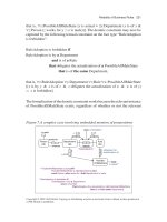
Figure 2.3 illustrates the OSI model in schematic format, showing the
various levels of the model with respect to a terminal device, such as a personal
computer accessing an application on a host computer system. Although
Figure 2.3 shows communications occurring via a modem connection on
a wide area network, the OSI model schematic is also applicable to local
area networks. Thus, the terminal shown in the figure could be replaced
by a workstation on an Ethernet network while the front-end processor
(FEP) would, via a connection to that network, become a participant on
that network.
Data Flow
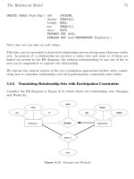
As data flows within an ISO network, each layer appends appropriate heading
information to frames of information flowing within the network, while
removing the heading information added by a lower layer. In this manner,
layer n interacts with layer n − 1 as data flows through an ISO network.
Figure 2.4 illustrates the appending and removal of frame header infor-
mation as data flows through a network constructed according to the ISO
Reference Model. Because each higher level removes the header appended by
a lower level, the frame traversing the network arrives in its original form at
its destination.
As you will surmise from the previous illustrations, the ISO Reference
Model is designed to simplify the construction of data networks. This sim-
plification is due to the potential standardization of methods and procedures
networking standards 47
Level 1
Level 2
Level 3
Level 4
Level 5
Level 6
Level 7
Network
Terminal
Modem
Modem
Application
Control
program
Access
method
FEP
Figure 2.3 OSI model schematic.
7
6
5
4
3
2
1
Layer
Application
Presentation
Session
Transport
Network
Data link
Physical
Application
Presentation
Session
Transport
Network
Data link
Physical
Outgoing
frame
Received
frame
AH AH
AH AH
AH
AH
AH
AH
AH
AH
AH
AH
PH
PH
PH
PH
PH
PH
PH
PH
PH
PH
Data
Data
Data
Data
Data
Data
Data
Data
Data
Data
Data Data
SH SH
SH
SH
SH
SH
SH
SH
TH TH
TH
TH
TH
TH
NH
NH
NH
NH
DHDH
Data bits Data bits
Legend:
DH, NH, TH, SH, PH and AH are appropriate headers Data Link, Network header,
Transport header, Session header, Presentation header and Application header
added to data as the data flows through an ISO Reference model network
Figure 2.4 Appending and removal of frame header information.
48 chapter two
to append appropriate heading information to frames flowing through a
network, permitting data to be routed to its appropriate destination following
a uniform procedure.
2.3 IEEE 802 Standards
The Institute of Electrical and Electronics Engineers (IEEE) Project 802 was
formed at the beginning of the 1980s to develop standards for emerging
technologies. The IEEE fostered the development of local area networking
equipment from different vendors that can work together. In addition, IEEE
LAN standards provided a common design goal for vendors to access a
relatively larger market than if proprietary equipment were developed. This,
in turn, enabled economies of scale to lower the cost of products developed
for larger markets.
The actual committee tasked with the IEEE Project 802 is referred to as the
IEEE Local and Metropolitan Area Network (LAN/WAN) Standards Commit-
tee. Its basic charter is to create, maintain, and encourage the use of IEEE/ANSI
and equivalent ISO standards primarily within layers 1 and 2 of the ISO Ref-
erence Model. The committee conducts a plenary meeting three times a year
and currently has 13 major working groups, each of which may have several
meetings per year at locations throughout the world.
802 Committees
Table 2.1 lists the IEEE 802 committees involved in local and metropolitan area
networks. In examining the lists of committees in Table 2.1, it is apparent that
the IEEE early on noted that a number of different systems would be required
to satisfy the requirements of a diverse end-user population. Accordingly, the
IEEE adopted the CSMA/CD, Token-Bus, and Token-Ring as standards 802.3,
802.4, and 802.5, respectively.
The IEEE Committee 802 published draft standards for CSMA/CD and
Token-Bus local area networks in 1982. Standard 802.3, which describes a
baseband CSMA/CD network similar to Ethernet, was published in 1983. Since
then, several addenda to the 802.3 standard have been adopted to govern the
operation of CSMA/CD on different types of media. Those addenda include
10BASE-2, which defines a 10-Mbps baseband network operating on thin
coaxial cable; 1BASE-5, which defines a 1-Mbps baseband network operating
on twisted-pair; 10BASE-T, which defines a 10-Mbps baseband network oper-
ating on twisted-pair; and 10BROAD-36, which defines a broadband 10-Mbps
network that operates on thick coaxial cable.
networking standards 49
TABLE 2.1 IEEE Series 802 Committees/Standards
802 Overview — Architecture
802.1 Bridging — Management
802.2 Logical Link Control
802.3 CSMA/CD Access Method
802.4 Token-Passing Bus Access Method
802.5 Token-Passing Ring Access Method
802.6 Metropolitan Area Networks (DQDB Access Method)
802.7 Broadband LAN
802.8 Fiber Optic Technical Advisory Group
802.9 Integrated Voice and Data Networks
802.10 Network Security
802.11 Wireless LANs
802.12 Demand Priority Access
The IEEE 802.3 committee includes a large number of projects that resulted
in the refinement and expansion of the CSMA/CD protocol. Some of those
projects were completed several years ago, while others are currently ongoing.
Table 2.2 lists nine examples of IEEE 802.3 CSMA/CD projects. A Fast Ether-
net, which is denoted as 802.3µ in Table 2.2, is an addendum to the 802.3
standard, which was finalized in 1995. 802.3z represents the 802 committee
project that was responsible for developing the Gigabit Ethernet standard.
The next major standard published by the IEEE was 802.4, which describes
a token-passing bus–oriented network for both baseband and broadband
transmission. This standard is similar to the Manufacturing Automation
Protocol (MAP) standard developed by General Motors.
The third major LAN standard published by the IEEE was based on IBM’s
specifications for its Token-Ring network. Known as the 802.5 standard,
it defines the operation of token-ring networks on shielded twisted-pair
cable at data rates of 1 and 4 Mbps. That standard was later modified to
acknowledge three IBM enhancements to Token-Ring network operations.
These enhancements include the 16-Mbps operating rate, the ability to release
a token early on a 16-Mbps network, and a bridge routing protocol known as
source routing.
50 chapter two
TABLE 2.2 IEEE 802.3 CSMA/CD Projects
803.2aa Maintenance Revision #5 (100Base-T)
802.3ab 1000Base-T
802.3ad Link Aggregation
802.3c vLAN tag
802.3ae 10 Gbps Ethernet
802.3ag Maintenance Revision #6
802.3i Ethernet (10BASE-T)
802.3µ Fast Ethernet
802.3x Full Duplex
802.3z Gigabit Ethernet
Two Ethernet standards that represent initial follow-on to the initial
standard are 802.3µ and 802.12, both of which have their foundation in
IEEE efforts that occurred during 1992. In that year the IEEE requested pro-
posals for ‘‘Fast Ethernet,’’ designed to raise the Ethernet operating rate from
10 Mbps to 100 Mbps. This request resulted in two initial proposals. One
proposal, now referred to as a series of 100BASE proposals, was developed
by a consortium that included Synoptics Communications, Inc., 3Com Cor-
poration, and Ungermann-Bass, Inc. This proposal retained the CSMA/CD
access proposal, which formed the basis for the operation of earlier ver-
sions of Ethernet. Now included in 802.3µ are 100BASE-TX, 100BASE-FX,
and 100BASE-T4.
100BASE-TX defines the specifications for 100-Mbps CSMA/CD over two
pairs of category 5 unshielded twisted-pair (UTP) cable. 100BASE-FX specifies
100-Mbps Ethernet over two pairs of optical fiber cable, while 100BASE-T4
defines the operation of 100-Mbps Ethernet over four pairs of category 3, 4,
and 5 UTP or shielded twisted-pair (STP) cable.
The second 100-Mbps proposal, which is now referred to as 100VG-
AnyLAN, was initially developed by AT&T Microelectronics and Hewlett-
Packard Company. This proposal replaced the CSMA/CD access protocol by
a demand-priority scheme that enables the support of Ethernet, Token-Ring,
FDDI, and other types of local area networks. Since this proposal described
operations on voice grade (VG) twisted pair, it received the mnemonic 100VG-
AnyLAN. Because the operation of 100VG-AnyLAN is based upon the passing
networking standards 51
of a token that is used to prioritize access to a network, the actual name of the
802.12 committee is Demand Priority Access.
During 1994, the IEEE 802.9 working group completed a document that
creates a 16.384-Mbps physical layer for operation on UTP category 3 or
higher cable. Referred to as isoENET, the document is technically referred to
as 802.9a. While both 100VG-AnyLAN and isoENET received a considerable
level of interest when they were proposed, they never achieved any significant
degree of commercial acceptance. Due to this, our coverage in this book of those
versions of Ethernet will be limited to a brief overview of each technology.
The CSMA/CD protocol requires stations to listen for activity before trans-
mitting data. This means that a four-wire connection with separate pairs
for transmit and receive cannot be operated simultaneously to transmit and
receive data, precluding true full-duplex operations from occurring. However,
when an Ethernet station is connected to a port on a LAN switch, the two wire
pairs between the station enable the switch port and workstation to simultane-
ously transmit and receive data without the possibility of a collision occurring.
This method of full duplex CSMA/CD transmission was standardized by the
IEEE as the 802.3x standard during 1996.
While the IEEE 802.3z standard for the operation of Gigabit Ethernet trans-
mission was completed during 1998, that standard was limited to defining
transmission at 1 Gbps over different types of optical fiber. It was not until
1999 that the 802.3ab standard was issued, which provided the physical layer
specification for 1 Gbps transmission over metallic twisted-pair standardized
as 1000BASE-T. Although it remained to be finalized, 10 Gbps Ethernet’s
physical layer specification over optical fiber was being worked on by the
IEEE 802.3ae project.
Data Link Subdivision
One of the more interesting facets of IEEE 802 standards was the initial
subdivision of the ISO Open System Interconnection Model’s data link layer
into two sublayers: logical link control (LLC) and medium access control
(MAC). Figure 2.5 illustrates the relationship between IEEE 802 local area
network standards and the first three layers of the OSI Reference Model.
The separation of the data link layer into two entities provides a mechanism
for regulating access to the medium that is independent of the method for
establishing, maintaining, and terminating the logical link between worksta-
tions. The method of regulating access to the medium is defined by the MAC
portion of each LAN standard. This enables the LLC standard to be applicable
to each type of network.
52 chapter two
802.1 High-level interface
(internet working)
802.2 Logical link control
Network
OSI
Reference
model
802.3
Medium
access
control
802.3
Physical
802.4
Medium
access
control
802.4
Physical
802.5
Medium
access
control
802.5
Physical
802.6
Medium
access
control
802.6
Physical
Data
link
Physical
Figure 2.5 Relationship between IEEE standards and the OSI Reference
Model.
Medium Access Control
The MAC sublayer is responsible for controlling access to the network. To
accomplish this, it must ensure that two or more stations do not attempt to
transmit data onto the network simultaneously. For Ethernet networks, this is
accomplished through the use of the CSMA/CD access protocol.
In addition to network access control, the MAC sublayer is responsible for
the orderly movement of data onto and off of the network. To accomplish this,
the MAC sublayer is responsible for MAC addressing, frame type recognition,
frame control, frame copying, and similar frame-related functions.
The MAC address represents the physical address of each station connected
to the network. That address can belong to a single station, can represent a
predefined group of stations (group address), or can represent all stations on
the network (broadcast address). Through MAC addresses, the physical source
and destination of frames are identified.
Frame type recognition enables the type and format of a frame to be
recognized. To ensure that frames can be processed accurately, frame control
prefixes each frame with a preamble, which consists of a predefined sequence
networking standards 53
of bits. In addition, a frame check sequence (FCS) is computed by applying an
algorithm to the contents of the frame; the results of the operation are placed
into the frame. This enables a receiving station to perform a similar operation.
Then, if the locally computed FCS matches the FCS carried in the frame, the
frame is considered to have arrived without error.
Once a frame arrives at a station that has the same address as the destination
address in the frame, that station must copy the frame. The copying operation
moves the contents of the frame into a buffer area in an Ethernet adapter card.
The adapter card removes certain fields from the frame, such as the preamble
and start of frame delimiter, and passes the information field into a predefined
memory area in the station into which the adapter card is inserted.
Refer to Chapter 4 for detailed information concerning Ethernet frame for-
mats, as well as information concerning how the MAC layer controls the
transmission and reception of data on an Ethernet local area network.
Logical Link Control
Logical link control frames are used to provide a link between network layer
protocols and media access control. This linkage is accomplished through the
use of service access points (SAPs), which operate in much the same way as
a mailbox. That is, both network layer protocols and logical link control have
access to SAPs and can leave messages for each other in them.
Like a mailbox in a post office, each SAP has a distinct address. For the
logical link control, a SAP represents the location of a network layer process,
such as the location of an application within a workstation as viewed from the
network. From the network layer perspective, a SAP represents the place to
leave messages concerning the network services requested by an application.
LLC frames contain two special address fields, known as the destination
services access point and the source services access point. The destination
services access point (DSAP) is one byte in length and specifies the receiving
network layer process. The source services access point (SSAP) is also one
byte in length. The SSAP specifies the sending network layer process. Both
DSAP and SSAP addresses are assigned by the IEEE. Refer to Chapter 4 for
detailed information concerning LLC frame formats and data flow.
Additional Sublayering
As previously mentioned, the standardization of high-speed Ethernet resulted
in an additional sublayer at the data link layer, and the subdivision of
the physical layer. Figure 2.6 illustrates the relationship between the first two
layers of the ISO Reference Model and the IEEE 802.3µ Fast Ethernet sublayers.
54 chapter two
Logical link control
Media access control
Reconciliation sublayer
Medium-independent interface
Physical coding sublayer
Physical medium attachments
Physical medium dependent
Physical
layer
Data
link
layer
Figure 2.6 IEEE 802.3µ sublayering.
The additional sublayering illustrated in Figure 2.6 became necessary, as it
was desired to support different media with one standard. To accomplish
this required the physical layer to be independent from the data link layer,
because there can be different coding schemes used to support transmission
on different types of media.
To retain the CSMA/CD access protocol while supporting the use of different
media required the use of different connectors, resulting in the introduction of
a physical medium-dependent (PMD) sublayer. Because different data coding
schemes are required to support 100 Mbps on different types of media, a
physical coding sublayer was introduced. This sublayer defines the coding
method used for transmission on different types of media. To map messages
from the physical coding sublayer onto the transmission media resulted in
those functions being performed by the physical medium attachment sublayer.
Thus, the physical layer was subdivided into three sublayers.
Although not shown on Figure 2.6, it should be noted that an Auto-
Negotiation function resides under the PMD. The Auto-Negotiation function
was added to provide an ease of migration from 10 Mbps Ethernet to 100 Mbps
Ethernet and results in the Media-Independent Interface (MII) supporting both
10 and 100 Mbps data transfer. To accomplish this the MII clock is capable of
operating at 2.5 MHz and 25 MHz.
At the data link layer an additional sublayer, known as the reconciliation
sublayer, was introduced. This sublayer is responsible for reconciling the MII
from the physical layer, with the MAC signal.
networking standards 55
Logical link control
Reconciliation
Gigabit media-independent
interface
Physical coding sublayer
Physical medium attachment
Physical medium dependent
Physical
layer
Data
link
layer
Media access control
Figure 2.7 Subdivision of the physical layer of Gigabit Ethernet.
Recognizing that Gigabit Ethernet would operate on different types of media
also resulted in the subdivision of its physical layer. That subdivision is
illustrated in Figure 2.7.
The reconciliation sublayer represents a transparent interface between the
MAC sublayer and the physical layer which decouples the MAC layer from
the physical layer. The Gigabit Media Independent Interface (GMII) includes
transmit and receive data paths that are 8 bits in width, which, when coupled
with a clock that now operates at 125 MHz, results in a data transfer capability
of 1 Gbps.
From a comparison of Figure 2.6 and Figure 2.7, you will note that the
sublayering of Gigabit Ethernet is similar to that of Fast Ethernet. However,
the sublayers perform different functions. For example, under Fast Ethernet
coding is based on the FDDI specification. In comparison, under Gigabit
Ethernet reliance is shifted to the physical sublayers previously specified for
the Fiber channel, as the latter operates at approximately Gigabit data rates
and was selected for use by the 802.38 project members.
2.4 Internet Standards
The Internet as we know it dates to 1967 when the Advanced Research
Projects Agency (ARPA), operating as a part of the United States Office of the
56 chapter two
Secretary of Defense, issued a Request for Proposal (RFP) for the creation of a
packet switching network. The result of the RFP was a contract issued to Bolt,
Beranek and Newmann (BBN), a then small company based in Cambridge,
MA, whose efforts resulted in a network that enabled scientists and educators
to share information. That network was known as ARPAnet.
RFC Evolution
In an effort to share information about the operation of ARPAnet, Steve Crocker,
a then graduate student at UCLA, published the first Request for Comment
(RFC) in April, 1969, which was titled ‘‘Host Software.’’ The term RFC was
used, as Mr Crocker wanted others to comment on the information he provided.
As ARPAnet expanded and evolved into the Internet, various organizations
came into being. The Internet Activities Board (IAB) became responsible for
Internet design and planning. Two task forces reside under the IAB — the Inter-
net Engineering Task Force (IETF) and the Internet Research Task Force (IRTF).
The responsibility of the IETF involves the coordination of various technical
aspects of the Internet to include the development and modification of proto-
cols that may be necessary to obtain a desired level of functionality.
The IAB is currently responsible for defining protocols and operational
procedures that require both dissemination to the Internet community and
archiving. To accomplish this, the IAB primarily issues documents known
as Requests for Comments (RFCs), the majority of which begin as working
memorandums issued by the IETF.
Types and Submission
There are several types of RFCs. Types of RFCs can include a Draft Standard
RFC, a Proposed Standard RFC, a Full Standard RFC, an Experimental RFC, a
Best Current Practice RFC and a ‘‘For Your Information’’ RFC. While RFCs are
not referred publications, they are technically reviewed by either individual
technical experts, the RFC editor, or members of a task force. Anyone can
submit a document for publication as an RFC. Once submitted to the RFC
editor the document may be edited to comply with certain format rules, which
are currently specified in RFC 2223, issued in October, 1997, which obsoleted
RFC 1543.
An initial RFC submission is usually treated as a Preliminary Draft and
is electronically distributed for comment. On its way to becoming a Full
Standard, and it should be noted that many RFCs are not intended to be
standards, the Preliminary Draft may first become a Proposed Standard.
networking standards 57
Preliminary
draft
Proposed
standard
Draft
standard
Standard
6 months
minimum
4 months
minimum
Time
Figure 2.8 Internet standards time track.
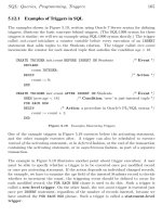
Figure 2.8 illustrates the typical track time for the development of an Internet
standard. Once a Preliminary Draft is submitted it can take approximately six
months for the receipt of comments concerning the draft and to allow the
draft to be moved forward to be published as a Proposed Standard, and either
dropped or promoted to a Draft Standard. After a review period of at least four
months, a Draft Standard can be recommended for adoption as a Standard
by the Internet Engineering Steering Group (IESC). The IESC consist of the
chairperson of the IETF and other members of that group, and it performs
an oversight and coordinating function for the IETF. Although the IESG is
responsible for recommending the adoption of an RFC as a Standard, the IAB
is responsible for the final decision concerning its adoption.
Obtaining RFCs
There are many Web sites where you can locate RFCs. The RFC Editor
maintains the official repository of all RFCs and indexes to them. The RFC
Editor web location is:
In addition to the RFC Editor web site there are many locations that mirror
RFC information. One popular web site is maintained by the Computer and
Information Science Department of Ohio State University. The address of that
web site is:
/>At this site you can review a complete index of all RFCs, view specific RFCs,
and obtain the capability to perform a keyboard search of a comprehensive
database of RFCs.
58 chapter two
2.5 Cabling Standards
Any discussion of Ethernet networks requires knowledge of both existing and
pending cabling standards. In this section we will focus our attention upon
the EIA/TIA-568 standard, first examining existing standards and then turning
our attention to developing cabling standards that may be in place by the time
you read this book.
EIA/TIA-568
The Electronics Industry Association/Telecommunications Industries Asso-
ciation ‘‘Commercial Building Telecommunications Standard,’’ commonly
referred to as EIA/TIA-568, was ratified in 1992. This standard specifies a
variety of building cabling parameters, ranging from backbone cabling used
to connect a building’s telecommunication closets to an equipment room, to
horizontal cabling used to cable individual users to the equipment closet.
The standard defines the performance characteristics of both backbone and
horizontal cables as well as different types of connectors used with different
types of cable.
Backbone Cabling
Four types of media are recognized by the EIA/TIA-568 standard for backbone
cabling. Table 2.3 lists the media options supported by the EIA/TIA-568
standard for backbone cabling.
Horizontal Cabling
As previously indicated, horizontal cabling under the EIA/TIA-568 standard
consists of cable that connects equipment in a telecommunications closet to
a user’s work area. The media options supported for horizontal cabling are
TABLE 2.3 EIA/TIA-568 Backbone Cabling Media Options
Media Type Maximum Cable Distance
100-ohm UTP 800 meters (2624 feet)
150-ohm STP 700 meters (2296 feet)
50-ohm thick coaxial cable 500 meters (1640 feet)
62.5/125-µ multimode optical fiber 2000 meters (6560 feet)
networking standards 59
the same as specified for backbone cabling, with the exception of coaxial
cable for which 50-ohm thin cable is specified; however, cabling distances are
restricted to 90 meters in length from equipment in the telecommunications
closet to a telecommunications outlet. This permits a patch cord or drop
cable up to 10 meters in length to be used to connect a user workstation
to a telecommunications outlet, resulting in the total length of horizontal
cabling not exceeding the 100-meter restriction associated with many LAN
technologies that use UTP cabling.
UTP Categories
One of the more interesting aspects of the EIA/TIA-568 standard is its recogni-
tion that different signaling rates require different cable characteristics. This
resulted in the EIA/TIA-568 standard initially classifying UTP cable into five
categories. Those categories and their suitability for different types of voice
and data applications are indicated in Table 2.4.
In examining the entries in Table 2.4, note that categories 3 through 5
support transmission with respect to indicated signaling rates. This means
that the ability of those categories of UTP to support different types of LAN
transmission will depend upon the signaling method used by different LANs.
For example, consider a LAN encoding technique that results in 6 bits encoded
into 4 signaling elements that have a 100-MHz signaling rate. Through the use
of category 5 cable, a data transmission rate of 150 Mbps ((6/4) × 100) could
be supported.
Category 3 cable is typically used for Ethernet and 4 Mbps Token-Ring
LANs. Category 4 is normally used for 16-Mbps Token-Ring LANs, while cat-
egory 5 cable supports 100-Mbps Ethernet LANs, such as 100VG-AnyLAN
TABLE 2.4 EIA/TIA-568 UTP Cable Categories
Category 1 Voice or low-speed data up to
56 Kbps; not useful for LANs.
Category 2 Data rates up to 1 Mbps.
Category 3 Supports transmission up to
16 MHz.
Category 4 Supports transmission up to
20 MHz.
Category 5 Supports transmission up to
100 MHz.
60 chapter two
and 100BASE-T, and will support ATM to the desktop at a 155-Mbps
operating rate. Two additional metallic cable categories being considered for
standardization are category 5 extended (cat 5e) and category 6. Category 5e
represents more stringent existing specifications as well as specifications for
existing parameters that we will shortly review. Although cat 5e is only speci-
fied for operations up to 100 MHz, it is used to support 1000BASE-T. However,
the proposed cat 6 standard that will support signaling up to 200 MHz should
eventually become the preferred cable for supporting Gigabit Ethernet over
copper media.
Cable Specifications
There are two basic metrics that define the capability of EIA/TIA-568 cable
with respect to the signaling rate they support, which in turn defines the cable
category. Those metrics are attenuation and near-end crosstalk (NEXT).
Attenuation
Attenuation represents the loss of signal power as a signal propagates from
a transmitter at one end of a cable toward a receiving device located at the
distant end of the cable. Attenuation is measured in decibels (dB) as indicated:
Attenuation = 20 log
10
(transmit voltage)
receive voltage
For those of us a little rusty with logarithms, let’s examine a few examples
of attenuation computations. First, let’s assume the transmit voltage was 100,
while the receive voltage was 1. Then,
Attenuation = 20 log
10
(100)
1
= 20 log
10
100
The value of log
10
100 can be obtained by determining the power to which
10 should be raised to equal 100. Because the answer is 2(10
2
= 100),log
10
100
has a value of 2, and 20 log
10
100 then has a value of 40.
Now let’s assume the transmit voltage was 10 while the receiver voltage was
1. Then,
Attenuation = 20 log
10
(10)
1
= 20 log
10
10
Because the value of log
10
10 is 1(10
1
= 10),then20log
10
10 has a value of 20.
From the preceding, note that a lower level of signal power loss results in a
lower level of attenuation.
networking standards 61
NEXT
Crosstalk represents the electromagnetic interference caused by a signal on
one wire pair being emitted onto another wire pair, resulting in the generation
of noise. Because transmit and receive pairs are twisted and the transmit
signal is strongest at its source, the maximum level of interference occurs at
the cable connector and decreases as the transmit signal traverses the cable.
Recognizing this fact of physics, crosstalk is measured at the near end, hence
the term near-end crosstalk (NEXT).
NEXT denotes the induced or coupled signal flowing from the transmit
pair to the receive pair even though the two pairs are not interconnected.
Mathematically, NEXT is defined in decibels (dB) as follows:
NEXT = 20 log
10
(transmitted voltage)
coupled voltage
In the preceding equation the transmit voltage represents the power placed on
the transmit pair, while the coupled signal is measured on the receive pair at
the location where the transmit voltage was generated. Note that a larger dB
NEXT measurement is better as it indicates a lower level of crosstalk and is
the opposite of attenuation, because a lower attenuation reading indicates less
signal loss and is better than a higher reading for that parameter. Table 2.5
indicates the EIA/TIA-568 specification limits for categories 3, 4, and 5 UTP
cable. In examining Table 2.5, note that both attenuation and NEXT must
be measured over a range of frequencies. That range is based upon the
cable category. For example, because category 3 cable is designed to support
signaling rates up to 16 MHz, attenuation and NEXT should be measured up
to and including the highest signaling rate supported by that type of cable,
which is 16 MHz.
Other Metrics
When the EIA/TIA considered the development of additional cabling spec-
ifications, it recognized the need to include additional parameters in the
specifications it developed. Three of those additional specifications concern
power sum NEXT (PS NEXT), Equal Level Far End Crosstalk (EL FEXT) and
the power sum attenuation to crosstalk ratio (PS ACR).
PS NEXT
Power sum NEXT actually represents a computation and not an individual
measurement. PS NEXT is obtained by computing the algebraic summation of
62 chapter two
TABLE 2.5 EIA/TIA-568 Attenuation and NEXT Limits in dB
Frequency
Category 3 Category 4 Category 5
(MHz) Attenuation NEXT Attenuation NEXT Attenuation NEXT
1.0 4.2 39.1 2.6 53.3 2.5 60.3
4.0 7.3 29.3 4.8 43.3 4.5 50.6
8.0 10.2 24.3 6.7 38.2 6.3 45.6
10.0 11.5 22.7 7.5 36.6 7.0 44.0
16.0 14.9 19.3 9.9 33.1 9.2 40.6
20.0 — — 11.0 31.4 10.3 39.0
25.0 ————11.437.4
31.2 ————12.835.7
62.5 ————18.530.6
100.0 ————24.027.1
the individual NEXT effects on each pair by the other pairs in a cable. Because
1000BASE-T uses four pairs, PS NEXT represents an important measurement
for qualifying cabling required to support Gigabit Ethernet over copper media.
PS NEXT represents a measure of difference in signal strength between
disturbing pairs and a disturbed pair. This means that a larger number, which
represents less crosstalk, is more desirable than a small number that represents
more crosstalk.
EL FEXT
Equal Level Far End Crosstalk (EL FEXT) also represents a calculated speci-
fication and not a single measurement. EL FEXT is computed by subtracting
the attenuation of the disturbing pair from the Far End Crosstalk that the pair
introduces in adjacent pairs.
To illustrate the computation of EL FEXT, assume FEXT was measured to
be −47 dB while attenuation was determined to be −12 dB. Then, EL FEXT
becomes −47 − (−12) or −35 dB. Note that EL FEXT provides a normal-
ized computation based upon the length of a cable since attenuation varies
by length.
networking standards 63
TABLE 2.6 Recent and Emerging EIA/TIA Cable Specifications
Category 6
Specification Category 5 Category 5e (Proposed)
Frequency Range 1–100 MHz 1–100 MHz 1–200 MHz
Attenuation 24 dB 24 dB 21.7 dB
NEXT 27.1 dB 30.1 dB 39.9 dB
Power sum NEXT N/A 27.1 dB 37.1 dB
ACR 3.1 dB 6.1 dB 18.2 dB
Power sum ACR N/A 3.1 dB 15.4 dB
EL FEXT 17 dB 17.4 dB 23.2 dB
Power sum EL FEXT 14.4 dB 14.4 dB 20.2 dB
ReturnLoss 8dB 10dB 12.0dB
Propagation Delay 548 ns 548 ns 548 ns
DelaySkew 50ns 50ns 50ns
PS ACR
Similar to PS NEXT and EL FEXT, the power sum attenuation to crosstalk
ratio (PS ACR) represents a computation and not an individual measurement.
PS ACR is determined by computing an algebraic summation of individual
ACR effects, with four results at each end of a link being tested.
Because ACR represents a measure of attenuation to crosstalk as a ratio, PS
ACR also represents a summed ratio. Thus, a larger number that represents
more signal and less noise is more desirable than a smaller number, which
represents more noise and less signal.
Cat 5e and Cat 6
When this new edition was prepared, category 5e had been standardized while
category 6 was being proposed as a new specification. To provide a frame of
reference between the newly specified category 5e and proposed category 6
cabling, Table 2.6 provides a comparison of those specifications to category 5
cable. In examining Table 2.6 note that several category 5 specifications are
not actually specified by that cabling specification and are only listed for
comparison purposes.
chapter three
Ethernet Networks
From the title of this chapter, it is apparent that there is more than one type
of Ethernet network. From a network access perspective, there is actually
only one Ethernet network. However, the CSMA/CD access protocol used
by Ethernet, as well as its general frame format and most of its operating
characteristics, were used by the IEEE to develop a series of Ethernet-type
networks under the IEEE 802.3 umbrella. Thus, this chapter will first focus on
the different types of Ethernet networks by closely examining the components
and operating characteristics of Ethernet and then comparing its major features
with the different networks defined by the IEEE 802.3 standard. Once this
is accomplished, we will focus our attention on the wiring, topology, and
hardware components associated with each type of IEEE 802.3 Ethernet
network. This will enable us to examine the construction of several types of
802.3 networks using a variety of hardware devices and then illustrate how
those networks can be connected to one another — a process referred to as
internetworking.
Although significant advances in Ethernet technology have occurred over
the past decade, many features and constraints associated with newer tech-
nology are based upon the original technology. Due to this we will begin at
the beginning in this chapter and examine the characteristics of each Ethernet
Network in the order in which they were developed.
3.1 Ethernet
One of the key concepts behind Ethernet — that of allocating the use of a shared
channel — can be traced to the p ioneering efforts of Dr. Norman Abramson
and his colleagues at the University of Hawaii during the early 1970s. Using a
ground-based radio broadcasting system to connect different locations through
the use of a shared channel, Abramson and his colleagues developed the con-
cept of listening to the channel before transmission, transmitting a frame of
65
Ethernet Networks: Design, Implementation, Operation, Management.
Gilbert Held
Copyright
2003 John Wiley & Sons, Ltd.
ISBN: 0-470-84476-0
66 chapter three
information, listening to the channel output to determine whether a collision
occurred, and, if it did, waiting a random period of time before retransmission.
The resulting University of Hawaii ground-based radio broadcasting system,
called ALOHA, formed the basis for the development of numerous channel
contention systems, including Ethernet. In addition, the subdivision of trans-
mission into frames of data was the pioneering work in the development of
packet-switching networks. Thus, Norman Abramson and his colleagues can
be considered the forefathers of two of the most important communications
technologies, contention networks and packet-switching networks.
Evolution
The actual development of Ethernet occurred at the Xerox Palo Alto Research
Center (PARC) in Palo Alto, California. A development team headed by
Dr. Robert Metcalfe had to connect over 100 computers on a 1-km cable. The
resulting system, which operated at 2.94 Mbps u sing the CSMA/CD access
protocol, was referred to as ‘‘Ethernet’’ in a memorandum authored by Met-
calfe. He named it after the luminiferous ether through which electromagnetic
radiation was once thought to propagate.
During its progression from a research-based network into a manufactured
product, Ethernet suffered several identity crises. During the 1970s, it endured
such temporary names as the ‘‘Alto Aloha Network’’ and the ‘‘Xerox Wire.’’
After reverting to the original name, Xerox decided, quite wisely, that the
establishment of Ethernet as an industry standard for local area networks
would be expedited by an alliance with other vendors. A resulting alliance
with Digital Equipment Corporation and Intel Corporation, which was known
as the DIX Consortium, resulted in the development of a 10-Mbps Ethernet net-
work. It also provided Ethernet with a significant advantage over Datapoint’s
ARCNet and Wang Laboratories’ Wangnet, proprietary local area networks
that were the main competitors to Ethernet during the 1970s.
The alliance between Digital Equipment, Intel, and Xerox resulted in the
publication of a ‘‘Blue Book Standard’’ for Ethernet Version 1. An enhance-
ment to that standard occurred in 1982 and is referred to as Ethernet Version 2
or Ethernet II in many technical publications. Although the DIX Consortium
submitted its Ethernet specification to the IEEE in 1980, it wasn’t until 1982
that the IEEE 802.3 CSMA/CD standard was promulgated. Because the IEEE
used Ethernet Version 2 as the basis for the 802.3 CSMA/CD standard, and
Ethernet Version 1 has been obsolete for over approximately two decades, we
will refer to Ethernet Version 2 as Ethernet in the remainder of this book.
ethernet networks 67
Network Components
The 10-Mbps Ethernet network standard originally developed by Xerox,
Digital Equipment Corporation, and Intel was based on the use of five hard-
ware components. Those components include a coaxial cable, a cable tap,
a transceiver, a transceiver cable, and an interface board (also known as
an Ethernet controller). Figure 3.1 illustrates the relationships among Ether-
net components.
Coaxial Cable
One of the problems faced by the designers of Ethernet was the selection of an
appropriate medium. Although twisted-pair wire is relatively inexpensive and
easy to use, the short distances between twists serve as an antenna for receiving
electromagnetic and radio frequency interference in the form of noise. Thus,
the use of twisted-pair cable restricts the network to relatively short distances.
Coaxial cable, however, has a dielectric shielding the conductor. As long
as the ends of the cable are terminated, coaxial cable can transmit over
greater distances than twisted-pair cable. Because the original development of
Ethernet was oriented toward interconnecting computers located in different
Transceiver
cable
Transceiver
Interface board
(controller)
in computer
Cable tap
Coaxial cable
Cable
core
Figure 3.1 Ethernet hardware components. When thick coaxial cable is used
for the bus, an Ethernet cable connection is made with a transceiver cable and
a transceiver tapped into the cable.
68 chapter three
buildings, the use of coaxial cable was well suited for this requirement. Thus,
the initial selection for Ethernet transmission medium was coaxial cable.
There are two types of coaxial cable that can be used to form the main
Ethernet bus. The first type of coaxial cable specified for Ethernet was a rela-
tively thick 50-ohm cable, which is normally colored yellow and is commonly
referred to as ‘‘thick’’ Ethernet. This cable has a marking every 2.5 meters to
indicate where a tap should occur, if one is required to connect a station to the
main cable at a particular location. These markings represent the minimum
distance one tap must be separated from another on an Ethernet network.
The outer insulation or jacket of the yellow-colored cable is constructed using
PVC. A second popular type of 50-ohm cable has a Teflon jacket and is colored
orange-brown. The Teflon jacket coax is used for plenum-required installa-
tions in air-handling spaces, referred to as plenums, to satisfy fire regulations.
When installing a thick coaxial segment the cable should be rolled from a
common cable spool or cable spools manufactured at the same time, referred
to as a similar cable lot, to minimize irregularities between cables. Under
the Ethernet specifications when the use of cable from different lots cannot
be avoided, cable sections should be used that are either 23.4 m, 70.2 m,
or 117 m in length. Those cable lengths minimize the possibility of exces-
sive signal reflections occurring due to variances in the minor differences
in cable produced by different vendors or from different cable lots from the
same vendor.
A second type of coaxial cable used with Ethernet is smaller and more
flexible; however, it is capable of providing a transmission distance only one-
third of that obtainable on thick cable. This lighter and more flexible cable is
referred to as ‘‘thin’’ Ethernet and also has an impedance of 50 ohms. When
the IEEE standardized Ethernet, the thick coaxial cable–based network was
assigned the designation 10BASE-5, while the network that uses the thinner
cable was assigned the designator 10BASE-2. Later in this chapter we will
examine IEEE 802.3 networks under which 10BASE-5, 10BASE-2, and other
Ethernet network designators are d efined.
Two of the major advantages of thin Ethernet over thick cable are its cost
and its use of BNC connectors. Thin Ethernet is significantly less expensive
than thick Ethernet. Thick Ethernet requires connections via taps, whereas
the use of thin Ethernet permits connections to the bus via industry standard
BNC connectors that form T-junctions.
Transceiver and Transceiver Cable
Transceiver is a shortened form of transmitter-receiver.Thisdevicecon-
tains electronics to transmit and receive signals carried by the coaxial cable.
ethernet networks 69
The transceiver contains a tap that, when pushed against the coaxial cable,
penetrates the cable and makes contact with the core of the cable. Ether-
net transceivers are used for broadband transmission on a coaxial cable and
usually include a removable tap assembly. The latter enables vendors to
manufacture transceivers that can operate on thick and thin coaxial cable,
enabling network installers to change only the tap instead of the entire device
and eliminating the necessity to purchase multiple types of transceivers to
accommodate different media requirements. In books and technical literature
the transceiver, its tap, and its housing are often referred to as the medium
attachment unit (MAU).
The transceiver is responsible for carrier detection and collision detection.
When a collision is detected during a transmission, the transceiver places
a special signal, known as a jam, on the cable. This signal, described in
Chapter 4, is of sufficient duration to propagate d own the network bus and
inform all of the other transceivers attached to the bus node that a collision
has occurred.
The cable that connects the interface board to the transceiver is known
as the transceiver cable. This cable can be up to 50 meters (165 feet) in
length and contains five individually shielded twisted pairs. Two pairs are
used for data in and data out, and two pairs are used for control signals in
and out. The remaining pair, which is not always used, permits the power
from the computer in which the interface board is inserted to power the
transceiver.
Because collision detection is a critical part of the CSMA/CD access protocol,
the original version of Ethernet was modified to inform the interface board that
the transceiver collision circuitry is operational. This modification resulted in
each transceiver’s sending a signal to the attached interface board after every
transmission, informing the board that the transceiver’s collision circuitry
is operational. This signal is sent by the transceiver over the collision pair
of the transceiver cable and must start within 0.6 microseconds after each
frame is transmitted. The duration of the signal can vary between 0.5 and
1.5 microseconds. Known as the signal quality error and also referred to
as the SQE or heartbeat, this signal is supported by Ethernet Version 2.0,
published as a standard in 1982, and by the IEEE 802.3 standard. Although
the heartbeat (SQE) is between the transceiver and the system to which it is
attached, under the IEEE 802.3 standard transceivers attached to a repeater
must have their heartbeat disabled.
The S QE signal is simply a delayed response by a few bit times to the
transmission of each frame, informing the interface card that everything is
working normally. Because the SQE signal only flows from the transceiver