Ethernet Networks: Design, Implementation, Operation, Management 4th phần 3 pptx
Bạn đang xem bản rút gọn của tài liệu. Xem và tải ngay bản đầy đủ của tài liệu tại đây (520.77 KB, 60 trang )
ethernet networks 105
used at both ends of the segment. Otherwise, the mixing of 10BASE-FL and
FOIRL equipment reduces the maximum length of the optical segment to
1000 meters.
The development of the 10BASE-FL standard was intended as a replace-
ment for the older FOIRL specification. Unlike FOIRL that was restricted to
providing an optical connection between repeaters, 10BASE-FL enables an
optical segment to be routed between two workstations, two repeaters, or
between a workstation and a repeater port.
The actual connection of a copper-based network node to a 10BASE-FL seg-
ment can be accomplished in one of two ways. First, a stand-alone fiber-optic
MAU (FOMAU) can be connected via the 15-pin AUI connector on a network
adapter to provide an electrical-to-optical conversion capability. A second
method is to use a 10BASE-T/FL converter. The latter is used when only a
10BASE-T port is available on a NIC. Both the 10BASE-FL FOMAU and the
10BASE-T/FL converter include two fiber-optic connectors, one for transmit-
ting and one for receiving data. Some 10BASE-T/FL converters include two
RJ-45 connectors that provide a high degree of cabling flexibility. One RJ-45
connector functions as a crossover cable and allows hub-to-hub communica-
tions via optical media, while the second connector is for workstations that
use a straight-through connection.
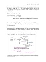
The top portion of Figure 3.24 illustrates the connection of a workstation to
a 10BASE-FL FOMAU via a 15-pin AUI connector. The lower portion of that
illustration shows the use of a 10BASE-T/FL converter. Both devices provide
you with the ability to transmit up to 2000 meters via a fiber link when a
10BASE-F-compliant optical device is at the other end of the optical link.
In addition to the use of a 10BASE-FL FOMAU and 10BASE-T/FL con-
verter, other types of converters have been developed to extend a fiber-optic
transmission capability to other types of Ethernet networks. For example, a
10BASE-2/FL converter enables you to extend the transmission distance of a
10BASE-2 network via a fiber-optic connection.
The creation of a 10BASE-F optical hub is accomplished by the inclusion of
two or more FOMAUs in the hub. This results in the hub becoming an optical
repeater, which retransmits data received on one port onto all other ports.
Under the 10BASE-F standard you can use multiple 10BASE-FL connections
to connect several individual workstations at distances up to 2000 meters to a
common hub equipped with FOMAU ports.
Network Media
When examining the potential use of a converter or a FOMAU, it is important
to verify the type of optical media supported. Multimode fiber (MMF) is
106 chapter three
Ethernet
NIC
AUI cable
10BASE-FL TX
FOMAU RX
Optical
cable
(a) Using a fiber-optic MAU (FOMAU)
Ethernet
NIC
UTP cable
10BASE-T/FL
Optical
cable
(b) Using a 10BASE-T/FL converter
H
W
Figure 3.24 Options for connection of a workstation to a 10BASE-FL
segment.
commonly used, with the most popular type of fiber having a 62.5-micron (µ)
fiber-optic core and a 125-µ outer cladding. This type of multimode fiber
is referenced by the numerics 62.5/125 µ. The wavelength of light used on
a 62.5/125-µ MMF fiber link is 850 nanometers (nm), and the optical loss
budget, a term used to reference the amount of optical power lost through
attenuation, should not exceed the range 9.7 to 19.0 dB, with the exact amount
dependent upon the type of fiber used. Table 3.3 provides a comparison of the
optical attenuation for 10BASE-FL and FOIRL for six types of multimode fiber.
In examining the entries in Table 3.3, you will note that 10BASE-FL has a
higher loss budget than FOIRL for each type of multimode fiber. This explains
why the transmission distance of 10BASE-FL optical repeaters exceeds the
distance obtainable using FOIRL repeaters.
The connectors used on the previously described multimode fi ber are
referred to as ST connectors. The ST connector represents a spring-loaded
bayonet connector whose outer ring locks onto the connection similar to
the manner by which BNC connector’s junction on 10BASE-2 segments. To
facilitate the connection process, an ST connector has a key on the inner
sleeve and an outer bayonet ring. To make a connection you would line up
the key on the inner sleeve of the ST plug with a slot on an ST receptacle,
push the connector inward and then twist the outer bayonet ring to lock the
ethernet networks 107
TABLE 3.3 Comparing the Loss Budget (Optical Attenuation) of 10BASE-FL
and FOIRL
Multimode, graded
index fiber size (µm)
50/125 50/125 50/125 62.5/125 83/125 100/140
Numerical aperture .20 .21 .22 .275 .26 .30
10BASE-FL
Loss budget (dB)
9.7 9.2 9.6 13.5 15.7 19.0
FOIRL
Loss budget (dB)
7.2 6.7 7.1 11.0 13.2 16.5
connection in place. This action not only results in a tight connection but, in
addition, provides a precise alignment between the two portions of fiber-optic
cable being joined.
It is important to note that the optical loss depends upon several factors.
First, the length of the fiber governs optical loss, with a typical fiber illuminated
at 850 nm having a loss between 4 dB and 5 dB per 1000 meters. Second, these
of more connectors results in a higher optical loss. Third and perhaps most
important to note since this is easy to rectify, if your connectors or fiber splices
are poorly made or if dirt, finger oil or dust resides on connector ends, you
will obtain a higher level of optical loss than necessary.
10BASE-FB
A second 10BASE-F specification is 10BASE-FB, with the B used to denote
a synchronous signaling backbone segment. The 10BASE-FB specification
enables the limit on the number of repeaters previously described in the 5-4-3
rule section to be exceeded. A 10BASE-FB signaling repeater is commonly
used to connect repeater hubs together into a repeated backbone network
infrastructure that can span multiple 2000-m links.
10BASE-FP
A third 10BASE-F specification was developed to support the connection
of multiple stations via a common segment that can be up to 500 meters
in length. Referred to as 10BASE-FP, the P references the fact that the end
segment is a fiber-passive system. Under the 10BASE-FP specification a single
fiber-optic passive-star coupler can be used to connect up to 33 stations. Those
stations can be located up to 500 meters from a hub via the use of a shared
fiber segment.
108 chapter three
Although 10BASE-FP provides a clustering capability that might represent
a practical networking solution to the requirements of some organizations, as
well as reduce the cost associated with the use of multiple individual optical
cables, most organizations prefer to link hubs together. Doing so also allows
the use of a single pair of optical cables; however, the transmission distance
to the cluster is then extended to 2000 meters.
3.4 High-Speed Ethernet
To differentiate Gigabit and 10 Gbps Ethernet from other versions of Ethernet
whose operating rates exceed 10 Mbps but have a maximum operating rate
one-tenth that of Gigabit, those versions of Ethernet that operate at or below
100 Mbps were classified as high-speed Ethernet and are covered in this
section. This enables Gigabit and 10 Gbps Ethernet to be covered as a separate
entity in Section 3.5.
There are three broad categories into which high-speed Ethernet networks
fall. The first two types of high-speed Ethernet networks are represented by de
jure standards for operations at 100 Mbps, while the third standard represents
an extension to 10BASE-T that operates at 16 Mbps. As discussed in Chapter 2,
the IEEE standardized two general types of 100-Mbps Ethernet networks, with
the 802.3µ standard defining three types of 100-Mbps CSMA/CD networks,
while the 802.12 standard defines a demand-priority operation that replaces
the CSMA/CD access protocol. The third high-speed Ethernet network is
considered as a high-speed network only when compared with the operating
rate of Ethernet networks developed before 1992. This type of network, referred
to as isochronous Ethernet (isoENET), operates at 16 Mbps. This section will
focus upon obtaining a overview of the operation and use of each of these
three types of Ethernet networks.
Isochronous Ethernet
Isochronous Ethernet, or isoENET, represents an extension to 10BASE-T
technology. Isochronous Ethernet adds time-sensitive multimedia support
through an addition of 6.144 Mbps of isochronous bandwidth to existing 10-
Mbps 10BASE-T Ethernet. Here, the term isochronous references a series of
repetitive time slots used for the transmission of constant bit-rate services at
the physical bit-transmission level.
Although isoENET received a considerable degree of publicity during the
early 1990s, it never received any significant degree of commercial accep-
tance. This was probably due to the development of Fast Ethernet, which
ethernet networks 109
provided over six times the transmission capacity of isoENET. However,
because isoENET provided time slots for the transmission of time-sensitive
information, its design in effect provided a Quality of Service (QoS) capability
that is worth examining.
Isochronous Ethernet dates to 1992, when National Semiconductor and
IBM, with support from Apple Computer, submitted the basics of isoENET
to the IEEE 802.9 Integrated Services Local Area Networks working group.
Better known by its trade names isoEthernet and isoENET, this technique was
standardized by the IEEE as standard 802.9a, with the official designation
Integrated Service Local Area Network (ISLAN16-T). Here, the T in the abbre-
viation denotes its capability to operate over twisted-pair wiring, while the
16 references its operating rate. In comparison with other Ethernet LANs that
are asynchronous, isoENET was developed to support the 8-KHz sampling
clock used as a worldwide standard for voice transmission. This synchro-
nization capability was layered on top of the 10-Mbps 10BASE-T operating
rate, enabling isoENET to support real-time communications in addition to
conventional 10BASE-T asynchronous LAN transmission.
Isochronous Ethernet represented a hybrid type of Ethernet network, com-
bining standard 10-Mbps 802.3 10BASE-T with a 6.144-Mbps isochronous
networking capability. The 6.144 Mbps of additional bandwidth was designed
to accommodate 96 integrated services digital network (ISDN) B-channels,
either individually or in multiple combinations of N × 64 Kbps. For example,
a videoconference requiring 128 Kbps of bandwidth would be assigned two 64-
Kbps channels, while digitized voice that requires 64 Kbps when pulse code
modulation (PCM) is used for digitization would be assigned one channel.
Besides being designed to support 96 ISDN B-channels, the isochronous
bandwidth supported one 64-Kbps ISDN D-channel for signaling and one
96-Kbps ISDN M-channel used to support ISDN maintenance functions.
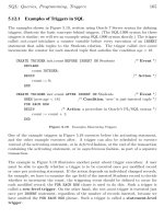
Figure 3.25 illustrates the allocation of isoENET bandwidth.
IsoENET replaced the Manchester encoding used by 10BASE-T with a 4B/5B
encoding scheme, which represents the data encoding method used by the
ANSI X3T9.5 FDDI standard. Under 4B/5B coding, each octet of data is split
into two four-bit nibbles (4B). Each nibble is then coded using five bits (5B),
resulting in an 80-percent level of utilization of the 20-MHz IEEE 802.3 clock
signal. In comparison, Manchester encoding provides a 50-percent utilization
of the 20-MHz clock. The change in the method of data coding provided an
additional 6.144-Mbps bandwidth on existing 10BASE-T wiring, connector,
and hub facilities. However, the u se of the additional bandwidth required
the installation of an isoENET hub and isoENET adapter cards for each local
area network node that requires an isochronous communications capability.
110 chapter three
16 Mbps
operating
rate
10 Mbps ethernet
6 Mbps (96 ISDN B-channels)
64 Kbps D-channel
96 Kbps M-channel
Signaling
Maintenance
Figure 3.25 Allocation of isoENET bandwidth.
Users who did not require an isochronous communications capability could
use their existing 10BASE-T adapter cards, and 802.3 traffic would not notice
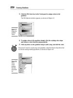
any change to the operation of a 10BASE-T network. Figure 3.26 illustrates
how an isoENET hub could support conventional 10BASE-T and isoENET
network nodes.
Although at one time about a dozen vendors manufactured isoENET prod-
ucts and its use provides a mechanism to extend multimedia to the desktop,
other Ethernet technologies dulled the demand for its 16-Mbps communica-
tions capability. The introduction of 100BASE-T and Gigabit Ethernet appears
to resolve the bandwidth crunch experienced by many networks that added
Internet connections and graphics-intensive applications. Because it appears
that greater bandwidth was more important than obtaining a videoconfer-
encing capability to the desktop, a majority of vendor and customer interest
became focused upon faster Ethernet solutions than that provided by isoENET.
Multimedia
PC
Video
server
Workstation
isoENET isoENETEthernet
Figure 3.26 isoENET supports the addition of 6.155 Mbps to nodes equipped
with isoENET adapter cards.
ethernet networks 111
Fast Ethernet
Fast Ethernet is not actually a local area network, but a term commonly used
to reference a series of three 100-Mbps physical-layer LAN specifications
in the IEEE 802.3µ addendum. Those specifications include 100BASE-TX,
100BASE-FX, and 100BASE-T4. Each specification maintains the use of the
MAC protocol used by earlier Ethernet/IEEE 802.3 standards, CSMA/CD.
100BASE-T specifies 100-Mbps operations using the CSMA/CD protocol
over two pairs of category 5 UTP cable. 100BASE-FX changes the LAN trans-
port media to two pairs of fiber, while 100BASE-T4 supports four pairs of
category 3, 4, and 5 UTP or STP cable. Table 3.4 provides a summary of the
three types of Fast Ethernet with respect to their IEEE media specification
designation, types of media supported, types of connectors supported, and
the coding scheme used.
100BASE-T Overview
At the beginning of this section we noted that the IEEE standardized two types
of 100 Mbps Ethernet networks. The 802.3µ standard defines three types of
CSMA/CD operations and is referred to as Fast Ethernet or 100BASE-T.
A second 100 Mbps Ethernet network standard resulted in the development
of a different access control mechanism, referred to as a demand priority
mechanism. The IEEE standardized the 100 Mbps LAN using a demand
priority mechanism as the 802.12 standard and its support of either Ethernet
or Token-Ring resulted in the name 100VG-AnyLAN being used to reference
the standard. Although both standards received a considerable degree of
interest, actual implementation and commercial success is another story. Of
TABLE 3.4 Fast Ethernet Functionality
IEEE Media
Specifications
Cable
Support
Connector
Support
Coding
Scheme
100BASE-TX Category 5 UTP (2-pair wire) RJ-45 4B/5B
100-ohm STP (2-pair wire) DB-9
100BASE-FX 62.5/125-micron fiber-optic cable
(2 multimode fibers)
SC or ST 4B/5B
100BASE-T4 Category 3, 4, or 5 UTP (4-pair wire) RJ-45 8B6T
Legend: UTP, unshielded twisted pair; STP, shielded twisted pair.
112 chapter three
the two standards 100BASE-T is by far a commercial success while 100VG-
AnyLAN is anything but. Thus, the primary focus of our attention in the
remaining of this chapter will be upon 100BASE-T, although we will briefly
conclude this section with an overview of the technology associated with
100VG-AnyLAN.
The standardization of 100BASE-T required an extension of previously
developed IEEE 802.3 standards. In the definition process of standard-
ization development, both the Ethernet media access control (MAC) and
physical layer required adjustments to permit 100-Mbps operational sup-
port. F or the MAC layer, scaling its speed to 100 Mbps from the 10BASE-T
10-Mbps operational rate required a minimal adjustment, because in the-
ory the 10BASE-T MAC layer was developed independently of the data
rate. For the physical layer, more than a minor adjustment was required,
because Fast Ethernet was designed to support three types of media. Using
work developed in the standardization process of FDDI in defining 125-
Mbps full-duplex signaling to accommodate optical fiber, UTP, and STP
through physical media-dependent (PMD) sublayers, Fast E thernet borrowed
this strategy. Because a mechanism was required to map the PMD’s continu-
ous signaling system to the start-stop half-duplex system used at the Ethernet
MAC layer, the physical layer was subdivided. This subdivision is illustrated
in Figure 3.27.
Note that the version of Fast Ethernet that operates using four pairs of
telephone-grade twisted pair wire is known as 100BASE-T4, while 100BASE-
TX operates over two pairs of data-grade twisted-pair. The third version of
Fast Ethernet, which operates over fiber-optic media, is 100BASE-FX. The
Link
layer
Physical
layer
100-Mbps
ethernet MAC
Convergence
sublayer (CS)
Physical media dependent
sublayer (PMD)
Four-pair
unshielded
twisted pair
Two-pair
Data-grade
twisted pair
Fiber
optic
Figure 3.27 Fast Ethernet physical layering subdivision overview.
ethernet networks 113
PMD sublayer supports the appropriate media to be used, while the conver-
gence sublayer (CS), which was later renamed the physical coding sublayer,
performs the mapping between the PMD and the Ethernet MAC layer.
Although Fast Ethernet represents a tenfold increase in the LAN operating
rate from 10BASE-T to ensure proper collision detection, the 100BASE-T
network span was reduced to 200 meters, with a maximum of 100 meters
permitted between a network node and a hub. The smaller network diameter
reduces potential propagation delay. When coupled with a tenfold operating
rate increase and no change in network frame size, the ratio of frame duration
to network propagation delay for a 100BASE-T network is the same as for a
10BASE-T network.
In addition to reducing the 100BASE-T network span to 200 meters, the Fast
Ethernet specification recognized the need to provide an automatic capability
for equipment to support older 10BASE-T equipment. This automatic support
is in the form of an Auto-Negotiation mechanism referred to as Nway, which
will be covered later in this section.
Physical Layer
The physical layer subdivision previously illustrated in Figure 3.27, as indi-
cated in the title of the figure, presents an overview of the true layer
subdivision. In actuality, a number of changes were required at the phys-
ical layer to obtain a 10-Mbps operating rate. Those changes include the
use of three wire pairs for data (the fourth is used for collision detection),
8B6T ternary coding (for 100BASE-T4) instead of Manchester coding, and an
increase in the clock signaling speed from 20 MHz to 25 MHz. As indicated
in Table 3.5, in comparison to 10BASE-T the differences at the physical layer
resulted in a tenfold increase in the 100BASE-T operating rate.
When the specifications for Fast Ethernet were being developed, it was recog-
nized that the physical signaling layer would incorporate medium-dependent
functions if support was extended to two-pair cable (100BASE-TX) operations.
TABLE 3.5 100BASE-T System Through-
put Compared with 10BASE-T
Transmit on 3 pairs vs. 1 pair ×3.00
8B6T coding instead of Manchester ×2.65
20 to 25 MHz clock increase ×1.25
Total throughput increase 10.00
114 chapter three
To separate medium-dependent interfaces to accommodate multiple physical
layers, a common interface referred to as the medium-independent inter-
face (MII) was inserted between the MAC layer and the physical encoding
sublayer. The MII represents a common point of interoperability between the
medium and the MAC layer. The MII can support two specific data rates,
10 Mbps and 100 Mbps, permitting older 10BASE-T nodes to be supported
at Fast Ethernet hubs. To reconcile the MII signal with the MAC signal, a
reconciliation sublayer was added under the MAC layer, resulting in the
subdivision of the link layer into three parts — a logical link control layer,
a media access control layer, and a reconciliation layer. The top portion of
Figure 3.28 illustrates this subdivision.
That portion of F ast Ethernet below the MII, which is the new physical
layer, is now subdivided into four sublayers. The lower portion of Figure 3.28
illustrates the physical sublayers for 100BASE-T4 and 100BASE-TX.
The physical coding sublayer performs the data encoding, transmit, receive,
and carrier sense functions. Because the data coding method differs between
100BASE-T4 and 100BASE-TX, this difference requires distinct physical cod-
ing sublayers for each version of Fast Ethernet.
The physical medium attachment (PMA) sublayer maps messages from the
physical coding sublayer (PCS) onto the twisted-pair transmission media, and
vice versa.
The auto-negotiation block shown in Figure 3.28 is not actually a layer
but a function built into 100BASE-T4 and 100BASE-TX. As noted earlier in
this section, auto-negotiation provides 100BASE-T copper media ports and
adapters with the ability to automatically adjust to 10 or 100 Mbps operations.
The medium-dependent interface (MDI) sublayer specifies the use of a
standard RJ-45 connector. Although the same connector is used for 100BASE-
TX, the use of two pairs of cable instead of four results in different pin
assignments.
100BASE-T4
100BASE-T4 supports a 100-Mbps operating rate over four pairs of cate-
gory 3, 4, or 5 UTP wiring that supports a segment upto 100 meters in
length. Figure 3.29 illustrates the RJ-45 pin assignments of wire pairs used
by 100BASE-T4. Note that wire pairs D1 and D2 are unidirectional. As indi-
cated in Figure 3.29, three wire pairs are available for data transmission
and reception in each direction, while the fourth pair is used for collision
detection. Each wire pair is polarized, with one wire of the pair transporting
a positive (+) signal while the other transports a negative (−) signal. Thus,
ethernet networks 115
ISO
model
100BASE-T4 and 100BASE-TX
Logical link control (LLC)
Media access control (MAC)
Reconciliation sublayer (RS)
Medium-independent interface
Physical coding
sublayer
8B6T coding
Physical coding
sublayer
4B5B coding
(previously con-
vergence layer)
Physical medium
attachment
(PMA)
Physical medium
attachment
(PMA)
Auto
negotiation
Auto
negotiation
Medium
dependent
interface
Medium
dependent
interface
Medium
(4-pair)
Medium
(2-pair)
100BASE-T4 100BASE-TX
Data
link
layer
Physical
layer
Figure 3.28 100BASE-T4 versus 100BASE-TX physical and link layers.
1
2
3
4
5
6
7
8
1
2
3
4
5
6
7
8
Transmit D1
Receive D2
Bidirectional D3
Bidirectional D4
Node detects
collision on
channel D2
Hub detects
collision on
channel D1
Node Hub
Figure 3.29 100BASE-T4 pin assignments.
116 chapter three
another common mechanism used to denote the function of the pins in the
100BASE-T4 eight-pin connector is to denote their use (transmit TX, receive
RX, or bi-directional BI), the data pair (D1, D2, D3 or D4) and type of signal
(+ or −) transported. Based upon the preceding, Figure 3.30 illustrates the
signals transported by the 100BASE-T4 eight-in connector.
In examining the signals based upon pin position shown in Figure 3.30,
you can note that the interconnection of devices connected to a 100BASE-
T4 segment would require a crossover of signals. Otherwise, for example,
TX
−
D1+ wouldbecabledtoTX
−
D1+ and the transmission at one end
would not be placed onto the receive side at the other end. Thus, a sig-
nal crossover cable is normally required to interconnect a station to a hub
port. An exception to this is when the hub has the crossover function built
into the device, which is usually denoted by marketing on the port in
the form of a tilted X. Figure 3.31 illustrates the crossover cable wiring for
100BASE-T4.
In examining the 100BASE-T4 crossover cable note that the TX pair at one
end of a cable is connected or strapped to the RX pair at the other end of
the cable. In addition, the BI
−
D3 pair at one end is connected to the BI
−
D4
pair at the other end. Each of the cross-connections occurs in each direction
to provide a crossover cable. Because 100BASE-T4 can operate on category 3,
which is used for 10BASE-T, this feature enables many organizations to
migrate to a 100-Mbps network without changing their wiring infrastructure.
The 100BASE-T4 physical coding sublayer implements 8B6T block coding.
Under this coding technique, each block of eight input bits is transformed into
a unique code group of six ternary symbols. Figure 3.32 provides an overview
of the 8B6T coding process used by 100BASE-T4.
Figure 3.30 Signals transported on the 100BASE-T4
eight-pin connector.
ethernet networks 117
Pin
number Signal
1 TX_D1+
2 TX_D1−
3 RX_D2+
6 RX_D2−
4 BI_D3+
5 BI_D3−
7 BI_D4+
8
Pin
number
1
2
3
6
4
5
7
8BI_D4−
Signal
TX_D1+
TX_D1−
RX_D2+
RX_D2−
BI_D3+
BI_D3−
BI_D4+
BI_D4−
Figure 3.31 100BASE-T4 crossover wiring.
Input data stream
Output code groups
1 2 3 4 5 6 7 8
1 2 3 4 5 6 1 2 3 4 5 6 1 2 3 4 5 6
• • •
1 2 3 4 5 6 7 8 1 2 3 4 5 6 7 8
Figure 3.32 8B6T coding process.
The output code groups resulting from 8B6T coding flow out to three parallel
channels that are placed on three twisted pairs. Thus, the effective data rate
on each pair is 100 Mbps/3, or 33.33 Mbps. Because 6 bits are represented
by 8 bit positions, the signaling rate or baud rate on each cable pair becomes
33 Mbps × 6/8, or 25 MHz, which is the clock rate used at the MII sublayer.
100BASE-TX
100BASE-TX represents the use of two pairs of category 5 UTP cabling with
RJ-45 connectors or two pairs of category 5 STP cable terminated with the
common DB-9 communications connector used on the serial port of many
notebook computers.
Because UTP is relatively inexpensive and two pair is less costly than
four pair, 100BASE-TX represents a more popular version of Fast Ethernet
than 100BASE-T4. The UTP wire actually used must meet the EIA/TIA 568
category 5 wire specifications. A 100BASE-TX network requires a hub, and
the maximum cable run is 100 meters from hub port to node, with a maximum
network diameter of 200 meters.
Figure 3.33 illustrates the cabling of two pairs of UTP wires between a hub
and node to support 100BASE-TX transmission. One pair of wires is used for
118 chapter three
Hub port Network node
Pair 1
Pair 2
Pair 1
Pair 2
Figure 3.33 100BASE-TX cabling.
transmission, while the second pair is used for collision detection and recep-
tion of data. The use of a 125-MHz frequency requires the use of a data grade
cable. Thus, 100BASE-TX is based upon the use of category 5 UTP and STP.
Similar to 100BASE-T4, 100BASE-TX uses an eight-pin connector when
UTP is employed. Figure 3.34 illustrates the use of each of the eight pins. Note
that the transmit and receive data signals on each pair transport positive (+)
and negative (−) signals. Also note that 100BASE-TX transmission via UTP
uses the same pin assignments as 10BASE-T hardware, enabling the same
category 5 wiring system to be used without any change to wiring being
required. This provides network administrators with a considerable degree
of flexibility for upgrading from 10BASE-T to 100BASE-TX once category 5
cabling is installed.
Similar to our discussion concerning 100BASE-TX, when two stations are
connected over a segment the transmit data pins on one side must be wired
to the receive data pins on the distant end and vice versa. Thus, unless a hub
has a port with a built-in crossover you need to use a 100BASE-TX crossover
cable to connect a station to a hub. Figure 3.35 illustrates the connection of
pins required for a 100BASE-TX crossover cable.
Similar to 10BASE-T, 100BASE-TX has separate transmit and receive signal
paths. Because these paths can be simultaneously active 100BASE-TX can
support full duplex transmission. If STP cabling is used the connector will be
Figure 3.34 100BASE-TX eight pin connector used
with UTP.
ethernet networks 119
Pin
number Signal
1 TD1+
2 TD1−
3 RD2+
6 RD2−
Pin
number
1
2
3
6
Signal
TD1+
TD1−
RD2+
RD2−
Figure 3.35 100BASE-TX crossover cable.
Figure 3.36 100BASE-TX nine-pin D-connector for
STP use.
a nine-pin ‘‘D-type’’ connector similar to the ones used on the serial port of
notebook computers. Figure 3.36 illustrates the use of the pins on the 9-pin
D-connector.
Although the 100BASE-TX physical layer structure resembles the 100BASE-
T4 layer, there are significant differences between the two to accommodate
the differences in media used. At the physical coding sublayer, the 100-Mbps
start-stop bit stream from the MII is first converted to a full-duplex 125-Mbps
bit stream. This conversion is accomplished by the use of the FDDI PMD
as the 100BASE-TX PMD. Next, the data stream is encoded using a 4B5B
coding scheme. The 100BASE-TX PMD decodes symbols from the 125-Mbps
continuous bit stream and converts the stream to 100-Mbps start-stop data bits
when the data flow is reversed.
4B5B Coding
The use of a 4B5B coding scheme enables data and control information to
be carried in each symbol represented by a 5-bit code group. In addition,
120 chapter three
an inter-Stream fill code (IDLE) is defined, as well as a symbol used to
force signaling errors. Because 4 data bits are mapped into a 5-bit code, only
16 symbols are required to represent data. The remaining symbols not used
for control or to denote an IDLE condition are not used by 100BASE-TX and
are considered as invalid.
Table 3.6 lists the 4B5B 100BASE-TX code groups. Because an explanation
of the use of the control codes and IDLE code requires an examination of the
MAC frame, we will defer our discussion of those symbols until Chapter 4, as
frame formats are discussed in that chapter.
100BASE-FX
100BASE-FX represents the third 100BASE-T wiring scheme, defining Fast
Ethernet transmission over fiber-optic media. 100BASE-FX requires the use
of two-strand 62.5/125-micron multimode fiber media and supports the 4B5B
coding scheme, identical to the one used by 100BASE-TX.
100BASE-FX provides an extended network diameter of up to 400 meters.
However, in a mixed 100BASE-T4 and 100BASE-FX environment, the
collision domain should not exceed 231 meters, consisting of 100 meters
for 100BASE-T4 and 131 meters for 100BASE-FX. Concerning connectors,
100BASE-FX supports both ST and SC fiber connectors, which were originally
defined for FDDI.
Network Construction and Use
Similar to 10-Mbps Ethernet networks, you can use adapter cards, cable,
and hubs to construct a variety of Fast Ethernet networks to satisfy different
organizational network requirements. However, when doing so, it is important
to understand the r ole of repeaters in a Fast Ethernet environment, as the
standard defines two types, each having a different effect upon network
construction.
Repeater Rules
When we examined Ethernet we discussed the 5-4-3 rule, which applied to a
common type of repeater. When we discuss Fast Ethernet we must consider
two types of repeaters, referred to as Class I and Class II repeaters.
ethernet networks 121
TABLE 3.6 4B/5B Code Groups
PCS Code Group MII (TXD/RXD)
4 3 2 1 0 Name 3 2 1 0 Interpretation
DATA
11110 0 0000 Data0
01001 1 0001 Data1
10100 2 0010 Data2
10101 3 0011 Data3
01010 4 0100 Data4
01011 5 0101 Data5
01110 6 0110 Data6
01111 7 0111 Data7
10010 8 1000 Data8
10011 9 1001 Data9
10110 A 1010 DataA
10111 B 1011 DataB
11010 C 1100 DataC
11011 D 1101 DataD
11100 E 1110 DataE
11101 F 1111 DataF
IDLE
11111 I IDLE:
Used as inter-Stream fill code
CONTROL
1 1 0 0 0 J Start-of-stream delimiter, part 1 of 2;
always used in pairs with K.
1 0 0 0 1 K Start-of-stream delimiter, part 2 of 2; always
used in pairs with J.
(continued overleaf )
122 chapter three
TABLE 3.6 (Continued)
PCS Code Group MII (TXD/RXD)
43210 Name 3210 Interpretation
0 1 1 0 1 T End-of-stream delimiter, part 1 of 2;
always used in pairs with R.
0 0 1 1 1 R End-of-stream delimiter, part 2 of 2;
always used in pairs with T.
INVALID
0 0 1 0 0 H Transmit error; used to force signaling errors.
00000 V Invalidcode
00001 V Invalidcode
00010 V Invalidcode
00011 V Invalidcode
00101 V Invalidcode
00110 V Invalidcode
01000 V Invalidcode
01100 V Invalidcode
10000 V Invalidcode
11001 V Invalidcode
A Class I repeater has a greater budget for timing delay, enabling it to be used
to support dissimilar physical media segments that use dissimilar signaling
such as 100BASE-T4 and 100BASE-TX. This support is possible because the
greater timing budget of the Class I repeater enables it to translate the line
signal received on one port to a different type of signal for transmission
onto other ports. Only one Class I repeater can be installed in a segment. In
comparison, a Class II repeater has a lower budget for timing delay, resulting
in it being faster than a Class I repeater. This enables up to two Class II
repeaters to be used in a segment; however, in doing so the interrepeater cable
length is limited to 5 meters when data terminal equipment are 100 meters
from repeaters. Because a Class II repeater immediately repeats an incoming
signal onto all other ports other than the port data was received on without
a translation process being possible, it can only be used to interconnect
ethernet networks 123
segment types that use the same signaling method, such as 100BASE-TX and
100BASE-FX.
The actual span distance obtainable through the use of repeaters depends
upon the type of repeater used and the media cable. Figure 3.37 illustrates
the cable restrictions associated with Fast Ethernet. In examining the entries
in Figure 3.37, note that the repeater references a Fast Ethernet hub, because
the hub receives information on one port and rebroadcasts the received data
onto all other ports. To exceed the cable limits shown in Figure 3.37, you
must connect the workstation or hub port to a switch, bridge, or router,
which results in a n ew segment being established. Concerning those cable
limits, although all vendors support the first two cabling distances shown
in Figure 3.37a and 3.37b, there are minor differences in the construction
of Class II–type repeaters between some vendors that may reduce the span
distance from that shown in Figure 3.37c for a mixture of TX and FX or FX
usage. In addition, the use of two Class II repeaters manufactured by different
vendors can also result in a slight reduction from the span distances shown
(a)
(b)
(c)
(d)
Direction connection without repeaters
(TX = 100m, TX & FX = NA, FL1111 = 412m)
One class I repeater
(TX = 200m, TX & FX = 260.8m, FX = 272m)
Repeater
Class I
One class II repeater
(TX = 200m, TX & FX = 308.8m, FX = 320m)
Repeater
Class II
Two class II repeaters
(TX = 205m, TX & FX = 223m, FX = 228m)
Repeater
Class II
Repeater
Class II
5m
Figure 3.37 Fast Ethernet cable re-
strictions.
124 chapter three
in Figure 3.37d for a mixture of TX and FX and FX r epeater use. Thus, it
is highly recommended to check vendor specification sheets concerning the
network guidelines associated with a particular type of repeater.
Because 100BASE-T4 and 100BASE-TX preserve the 10BASE-T MAC layer,
both standards are capable of interoperability with existing 10BASE-T net-
works as well as with other low-speed Ethernet technology. Through the use
of NWay autosensing logic, Fast Ethernet adapters, hub, and switch ports can
determine if attached equipment can transmit at 10 or 100 Mbps and adjust to
the operating rate of the distant device.
Autonegotiation
Auto-negotiation represents an optical feature which was added to the metal-
lic copper versions of Fast Ethernet and which is now incorporated into most
types of such hardware. The basis for auto-negotiation can be traced to a
technology referred to as NWay. NWay represents a cable and transmission
autosensing scheme proposed by National Semiconductor to the IEEE 802.3
standards group in May 1994. NWay incorporated an autosensing scheme to
permit Ethernet circuits to detect both the cable type and speed of incoming
Ethernet data, as well as enabled Ethernet repeaters to configure themselves
for correct network operations. Because NWay can detect 10-Mbps versus
100-Mbps operations, as well as half- and full-duplex transmission, it formed
the basis for autonegotiation which permits Ethernet circuits to be devel-
oped to automatically adjust to the operating rate and cabling scheme used.
This in turn simplifies the efforts of network managers and administrators,
because products incorporating autonegotiation are self-configurable and do
not require the setting of DIP switches or software parameters.
Auto-negotiation relies upon a modification to the link integrity test used
by 10BASE-T, replacing the link test pulse with a burst of pulses referred to as
fast link pulses (FLPs). Each FLP consists of a series of clock and data pulses,
with the data pulses used to form a 16-bit link code work (LCW).
Figure 3.38 illustrates the composition of the LCW. Note that the five-
bit selector field makes it possible for auto-negotiation to be supported by
Token-Ring (802.5) networks. In comparison, the eight-bit Technology Ability
field defines the technology supported. The Pause bit in the Technology
Ability Field was added to support full-duplex operations and when set
indicates if the device supports a Pause Mechanism. If so, the other device
can transmit a Pause Frame that will inform the receiving device to delay
its transmission. This form of flow control becomes necessary when a 100-
Mbps device communicates with a lower-speed device and the latter could be
overwhelmed with data. Thus, the 100-Mbps device will need to inform other
ethernet networks 125
00001 = 802.3 A0 = 10BASE-T
Selector field
S0 S1 S2 S3 S4 A0 A1 A2 A3 A4 A5 A6 A7 RF ACK NP
Technology ability field
00010 = 802.5 A1 = 10BASE-T Full Duplex
A2 = 100BASE-TX
A3 = 100BASE-TX Full Duplex
A4 = 100BASE-T4
A5 = Pause
RF = Remote Fault
ACK = Acknowledge
NP = Next Page
Figure 3.38 The format of the link code word.
devices to delay their transmission. In Chapter 4 when we examine the format
of different types of Ethernet frames we will also examine the Pause Frame.
Returning our attention to Figure 3.38, the Remote Fault indicates the
presence of a fault detected by the station at the opposite end of the link.
When this bit (RF) is set, it indicates that the distant device is in its link-failed
state, a condition typically resulting from a malfunctioning receiver or broken
cable. The next to last bit in the LCW is the ACK bit. This bit is used to
indicate the successful receipt of the previously transmitted LCW. The last
bit is the next page bit. When set this bit indicates that additional proprietary
information follows.
The link code word is transmitted on power-up or when requested by either
device on a link. The composition of fast link pulses appears similar to a
link integrity test, enabling a 10BASE-T device to respond. However, if the
remote station is a 100 Mbps device, its receive clock will be sufficient to
interpret the individual pulses that form the LCM, enabling the determination
of operations at 10 Mbps or 100 Mbps.
When two devices that support auto-negotiation have multiple capabilities,
they need to determine their highest performance mode of operation. In
doing so, they consult a priority table. Table 3.7 lists the priorities for auto-
negotiation from highest to lowest. Note that full duplex has a higher priority
than half duplex since the former has a higher throughput capability than
the latter.
Autonegotiation can operate on an individual end basis or with
autonegotiation-compliant devices at both ends of a twisted-pair link. An
example of this autonegotiation capability is shown in Figure 3.39 in which
126 chapter three
TABLE 3.7 Auto-negotiation Priority Table
Priority Technology Cable
1 100BASE-TX Full Duplex 2 pair, category 5
2 100BASE-T4 4 pair, category 3
3 100BASE-TX 2 pair, category 5
4 10BASE-T Full Duplex 2 pair, category 3
5 10BASE-T 2 pair, category 3
10BASE-T/100BASE-TX
switching hub with
autonegotiation
Autonegotiation
10BASE-T/
100BASE-TX
10BASE-T
Station
A
Station
B
Figure 3.39 Autonegotiation. Through the use of autonegotiation, the
10BASE-T/100BASE-TX switching hub will operate at 100 Mbps with
station A and at 10 Mbps with station B.
station A has a NIC with autonegotiation capability that is cabled to a 10BASE-
T/100BASE-TX switching hub whose port has an autonegotiation capability,
while station B has a conventional 10BASE-T NIC. In this example, the
hub port connected to station A would operate at 100 Mbps as 100BASE-TX
devices. In comparison, the hub port connection to station B would recognize
the 10BASE-T signals from station B and switch to 10BASE-T operations.
Operation
There are several network configurations you can consider for Fast Ethernet
operations. First, you can construct a 100BASE-TX network similar to a
10BASE-T network, using an appropriate hub and workstations that support
the specific network type. This type of network, commonly referred to as a
shared-media hub-based network, should be considered when most, if not all,
ethernet networks 127
network users access one or a limited number of servers to perform graphic-
intensive or similar bandwidth-intensive operations, and the sharing of the
100-Mbps transmission capability provides an acceptable average bandwidth
per network node. Figure 3.40a illustrates a Fast Ethernet shared-media hub
network configuration.
In examining Figure 3.40a note that the single CSMA/CD network represents
a collision domain. Here the term collision domain references a network
structure in which a collision will occur if two computers attached to the
network transmit at the same time. If one hub is wired to another or two
segments are joined together by a repeater the resulting network structure
continues to function as a single collision domain.
Another common use for Fast Ethernet is in its incorporation into one
or more ports in an Ethernet switch. An Ethernet switch can be viewed as
All connections operate at 100 Mbps.
Ser-
ver
Image/
video
server
Applica-
tion
server
Legend:
(a) Shared-media hub.
Some connections operate at 100 Mbps and some at 10 Mbps.
(b) 10/100 Mbps ethernet switch.
= Workstation
= Fat pipe
Figure 3.40 Fast Ethernet network applications.
128 chapter three
a sophisticated hub that can be programmed to transmit packets arriving
on one input port to a predefined output port. This is accomplished by
the switch reading the destination address in the frame and comparing
that address to a table of preconfigured address-port relationships. Readers
are referred to Chapter 5 for specific information concerning the operation
and use of Ethernet switches. In the interim, in examining the use of Fast
Ethernet switches, note that some older switches contain one or two 100-Mbps
operating ports, while the other ports are conventional 10BASE-T ports. Due
to economies of scale, most Fast Ethernet switches manufactured since the
beginning of the new millennium support 10/100-Mbps port operations on
all switch ports. The only major exception to the support of dual-speed auto-
negotiation ports is when the switch includes one or more Gigabit Ethernet
ports, with the latter restricted to operating at 1 Gbps. Typically you would
connect servers that have a heavy workload to 100-Mbps Fast Ethernet ports,
such as an image/video server and a database server. Figure 3.40 illustrates the
use of a 10/100-Mbps Ethernet switch. In examining Figure 3.40a and b, note
that the heavily shaded connections to all workstations in Figure 3.40a and to
the servers in Figure 3.40b represent 100-Mbps Fast Ethernet ports requiring
Fast Ethernet adapter cards to be installed in each server or workstation
connected to a 100-Mbps port. A common term used to reference the 100-Mbps
connection is fat pipe.
Because a Fast Ethernet port provides downward compatibility with
10BASE-T, you can interconnect conventional 10BASE-T hubs to a Fast
Ethernet shared-media hub or Fast Ethernet switch. Similar to having the
ability to interconnect two hubs to extend a Fast Ethernet network, you can
interconnect two switches. However, unlike the connection of hubs, which
extends the collision domain, each switch port will not forward collision
signals r eceived, enabling attached segments to operate independently of one
another. This means you can use LAN switches to construct larger networks
by interconnecting shared media segments via one or more switches.
Configuration Guidelines
To facilitate the creation of a Fast Ethernet network you need to consider
the maximum collision domain based upon the type of repeater used and the
media supported. In addition to the previously mentioned Class I and Class II
repeaters, you need to remember that a connection from a station to a hub
port represents a repeater on a single segment. With this in mind, Table 3.8
indicates the maximum collision domain based upon the class of repeater,
and the type of media used.
ethernet networks 129
TABLE 3.8 Fast Ethernet Maximum Collision Domain (Meters)
Type of Media
Type of Repeater Copper Fiber
Copper and
Fiber
(T4 and FX)
Copper and
Fiber
(TX and FX)
Single Segment 100 412 N/A N/A
One Class I 200 272 231
∗
260
∗
One Class II 200 320 N/A
†
308
∗
Two Class II 205 228 N/A
†
216
‡
Notes:
∗
Assumes 100 meters of copper and one fiber link.
†
Not applicable as T4 and FX cannot be interconnected using a Class II repeater.
‡
Assumes 105 meters of copper and one fiber link.
In examining the entries in Table 3.8 note that the first entry represents
a station-to-station connection with no intermediate repeaters. As indicated,
the maximum amount of cabling is 100 meters when copper is used and
412 meters when fiber-optic cable is employed. Figure 3.41 illustrates an
example of the structure of a Fast Ethernet network consisting of three shared
media hubs and a switch.
An examination of Figure 3.41 should be performed in conjunction with
the entries in Table 3.8 for the figure to be meaningful. For example, from
Table 3.8, the maximum collision domain for a class II repeater is 205 meters.
If you focus your attention upon collision domain 1 in Figure 3.41, you
will note that the inter-repeater segment is shown as 5 meters to keep the
maximum collision diameter equal or below 205 meters. You can increase the
inter-repeater segment length; however, you would then need to reduce the
other segments to ensure that the maximum collision diameter in the domain
does not exceed 205 meters.
Computer Bus Considerations
In addition to having to consider the type or types of NIC connectors, it
is also extremely important to consider the bus they are designed to work
with along with driver support for different operating systems. Some N ICs
are limited to one type of connector, requiring the purchase of a separate
converter if you decide to use a different media other than the media the NIC
was manufactured to directly support.