Firewalls For Dummies 2nd Edition phần 6 pdf
Bạn đang xem bản rút gọn của tài liệu. Xem và tải ngay bản đầy đủ của tài liệu tại đây (941.76 KB, 44 trang )
Table 12-4 External Firewall Filters to Access
an L2TP Tunnel Server
Protocol Transport Source Source Target IP Target Action
Protocol IP Port Port
IKE UDP Any 500 23.16.18.17 500 Allow
AH ID 51 Any 23.16.18.17 Allow*
ESP ID 50 Any 23.16.18.17 Allow
*AH is required only if the IPSec SA for the L2TP tunnel requires AH protection.
After the L2TP tunnel clients connect to the L2TP server, the RADIUS server
(located on the private network at IP address 192.168.222.3) authenticates
the client. After the tunnel client is successfully authenticated, the tunnel
client is assigned an IP address in the 23.16.18.128/25 address range. To allow
this access, the firewall rules shown in Table 12-5 must be configured at the
internal firewall.
Table 12-5 Internal Firewall Rules to Access
an L2TP Tunnel Server
Protocol Transport Source Source Target Target Action
Protocol IP Port IP Port
RADIUS UDP 23.16.18.17 Any 192.168.222.3 1812 Allow
Authenti-
cation
RADIUS
Accounting UDP 23.16.18.17 Any 192.168.222.3 1813 Allow
Internal Any 23.16.18. Any 192.168.222. Any Allow
Access 128/25 0/24
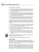
Deploying firewall rules for clients that support NAT-T
If the tunnel clients and tunnel server support NAT traversal (NAT-T), you can
deploy private network addressing in the DMZ, as shown in Figure 12-4.
204
Part III: Designing Network Configurations
As with a PPTP tunnel server, you must first define static address mappings
at the external firewall to ensure that the NAT discovery (NAT-D) and
NAT-T traffic are redirected to the tunnel server in the DMZ. These static
address mappings are shown in Table 12-6.
Table 12-6 L2TP with NAT-T Static Address Mapping
External IP Transport External Port Internal IP Internal Port
Address Protocol Address
23.16.16.5 UDP 500 192.168.223.22 500
23.16.16.5 UDP 4500 192.168.223.22 4500
After the static address mappings are defined, you must define what proto-
cols are allowed to pass through the external firewall to the DMZ. These fire-
wall rules are defined in Table 12-7.
Table 12-7 External L2TP/IPSec Firewall Rules for NAT-T Clients
Protocol Transport Source Source Target IP Target Action
Protocol IP Port Port
NAT-D UDP Any Any 192.168.223.22 500 Allow
NAT-T UDP Any Any 192.168.223.22 4500 Allow
Private Network DMZ Internet
Internal
server
Radius
server
Client
Client Client
Tunnel
server
Internet
23.16.16.5
39.100.24.5
External
client
192.168.223.22
192.168.223.0/24
192.168.222.3
192.168.222.0/24
Figure 12-4:
A two-
firewall
DMZ for
L2TP
services
that support
NAT-T
205
Chapter 12: Designing Demilitarized Zones with Multiple Firewalls
After the L2TP NAT-T tunnel clients connect to the L2TP server, the RADIUS
server (located on the private network at IP address 192.168.222.3) authenti-
cates the client. After the tunnel client is successfully authenticated, the tunnel
client is assigned an IP address in the 23.16.18.128/25 address range. To allow
this access, the firewall rules shown in Table 12-8 must be configured at the
internal firewall.
Table 12-8 Internal L2TP/IPSec Firewall Rules for NAT-T Clients
Protocol Transport Source Source Target Target Action
Protocol IP Port IP Port
RADIUS UDP 23.16.18.17 Any 192.168.222.3 1812 Allow
Authenti-
cation
RADIUS
Accounting UDP 23.16.18.17 Any 192.168.222.3 1813 Allow
Internal Any 23.16.18. Any 192.168.222. Any Allow
Access 128/25 0/24
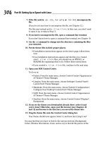
Deploying a Web server with
a SQL back end
Many Web sites collect information for registrations, newsletters, or purchas-
ing information. Typically, this information is stored in a database. Figure 12-5
shows a typical DMZ configuration for a Web server with a back-end Oracle
database located on the private network.
Private Network DMZ Internet
Internal
server
Oracle
server
Client
Client Client
Web
server
Internet
23.16.16.5
39.100.24.5
External
client
192.168.223.0/24
192.168.222.0/24
Figure 12-5:
A DMZ
hosting a
Web-based
database
application.
206
Part III: Designing Network Configurations
In Figure 12-5, the Web server located in the DMZ at IP address 192.168.223.13
must access an Oracle SQL back-end server using a SQL*Net connection. The
Oracle server is located in the private network at IP address 192.168.222.5.
To access the Web server, the firewall must allow both HyperText Transfer
Protocol (HTTP) and SSL-secure HTTP (HTTPS) to access the Web server.
In addition, the firewall must allow the Web server to communicate with the
Oracle Server using a SQL*Net connection. This requires connections to
the Oracle server listening on TCP port 1521.
The first step is to define the static address mapping that will redirect HTTP
and HTTPS packets received at the firewall to the Web server in the DMZ.
Table 12-9 shows the static address mappings that must be deployed at the
firewall in order to allow HTTP and HTTPS redirects to the Web server.
Table 12-9 Static Address Mappings
External IP Transport External Port Internal IP Internal Port
Address Protocol Address
23.16.16.5 TCP 80 192.168.223.13 80
23.16.16.5 TCP 443 192.168.223.13 443
After the static address mappings are defined, the external firewall rules must
be configured. Table 12-10 shows the firewall rules that must be implemented
in order to allow connections to the Web server.
Table 12-10 External Firewall Rules to Access
an Internal Web Server
Protocol Transport Source Source Target IP Target Action
Protocol IP Port Port
HTTP TCP Any Any 192.168.223.13 80 Allow
HTTPS TCP Any Any 192.168.223.13 443 Allow
The last step is to configure the internal firewall to allow the Web server to
connect to the Oracle back-end database in the private network. Table 12-11
shows the firewall rule that must be configured at the internal firewall.
207
Chapter 12: Designing Demilitarized Zones with Multiple Firewalls
Table 12-11 Internal Firewall Rule to Access
a Back-End SQL Server
Protocol Transport Source Source Target IP Target Action
Protocol IP Port Port
Oracle TCP 192.168.223.13 Any 192.168.222.5 1521 Allow
SQL*Net
This firewall rule allows only the Web server to connect to the Oracle
database — not the external Web clients themselves. By using forms on
HTML pages, the types of queries performed by the external clients are
restricted to specific types of queries.
Allowing private network users
to access the Internet
In many ways, the more difficult configurations with a two-firewall DMZ involve
outbound traffic rather than inbound traffic. This is because the original source
address information is typically translated at either the internal or external fire-
wall. Figure 12-6 shows a typical configuration in which internal clients on the
192.168.222.0/24 network will be allowed to access the Internet through the two
firewalls between the private network and the Internet.
In this scenario, the best strategy is to configure the firewalls starting at the
innermost firewall and work your way out to the firewall between the DMZ
and the Internet.
Private Network DMZ Internet
Client Client
Internet
192.168.222.0/24
39.100.24.5
23.16.16.5
192.168.223.0/24
External
client
ClientClient Client
Figure 12-6:
Allowing
outbound
traffic
through a
two-firewall
DMZ.
208
Part III: Designing Network Configurations
If you assume that the DMZ in Figure 12-6 uses 192.168.223.0/24 private net-
work addressing, the internal firewall requires the firewall rule shown in
Table 12-12 to allow outbound network traffic to the Internet from the private
network.
Table 12-12 Internal Firewall Outbound Firewall Rule
Protocol Transport Source Source Target Target Action
Protocol IP Port IP Port
Any Any 129.168.222.0/24 Any Any Any Allow
Because both the private network and the DMZ use private network address-
ing, the packets have the same source IP and port information when they
reach the external firewall (but before the packets are transmitted on the
Internet). To allow this traffic, the external firewall must be configured with
the same outbound firewall rule as the internal rule shown in Table 12-12.
The only catch is that the external firewall must be configured to perform
network address translation (NAT) on the outbound packets. All outbound
packets that arrive at the external firewall that originated from either the pri-
vate network or the DMZ must be translated to the external browsing address
configured at the firewall. Table 12-13 shows the network address translation
that must be performed at the external firewall.
Table 12-13 External Firewall NAT Configuration
Source IP Source Port Translated IP Translated Port Action
192.168.222.0/24 Any 23.16.16.5 Any Allow
192.168.223.0/24 Any 23.16.16.5 Any Allow
The scenario changes if the DMZ is configured to use public network
addressing. When public network addressing is used in the DMZ, the internal
firewall — not the external firewall — must be configured to perform network
address translation. Assuming that the internal firewall’s network interface
connected to the DMZ uses the IP address 23.16.18.5, the translation must be
configured at the internal firewall, as shown in Table 12-14, so that the out-
bound packets have public network addresses after they enter the DMZ.
209
Chapter 12: Designing Demilitarized Zones with Multiple Firewalls
Table 12-14 Internal Firewall NAT Configuration
Source IP Source Port Translated IP Translated Port Action
192.168.222.0/24 Any 23.16.18.5 Any Allow
The internal firewall must be configured to allow the original source addresses
to pass into the DMZ. You use the true IP addresses, as shown in Table 12-15,
rather than the translated addresses because the firewall rules are applied at
one firewall while the NAT takes place at the other firewall.
Table 12-15 Internal Firewall Outbound Firewall Rule
Protocol Transport Source Source Target Target Action
Protocol IP Port IP Port
Any Any 192.168.222.0/24 Any Any Any Allow
The external firewall requires different address information in its outbound
firewall rules because the original source address information has now been
translated to the common IP address of 23.16.18.5. Table 12-16 shows the out-
bound firewall rule required to allow private network users to access the
Internet.
Table 12-16 External Firewall Outbound Firewall Rule
Protocol Transport Source Source Target IP Target Action
Protocol IP Port Port
Any Any 23.16.18.5 Any Any Any Allow
210
Part III: Designing Network Configurations
Part IV
Deploying
Solutions Using
Firewall Products
In this part . . .
W
hat firewall product should you use to protect
your network? Several options are available. This
part shows you the steps to securing your network using
Windows or Linux. We also describe how to use a per-
sonal firewall, such as ZoneAlarm or Norton Personal
Firewall, or two popular enterprise firewalls: Microsoft
Internet Security and Acceleration (ISA) Server and Check
Point FireWall-1.
Vendors are all too happy to tell you to buy their firewall
product, which is no surprise. The last chapter in this
part helps you decide what features you need and what
firewall product to use. This part also gives you criteria
for choosing a firewall solution.
Chapter 13
Using Windows as a Firewall
In This Chapter
ᮣ Firewall functions in Windows
ᮣ Windows 98 and Windows Me
ᮣ Windows NT 4.0
ᮣ Windows 2000
ᮣ Windows XP
ᮣ Windows Server 2003
O
ver the years, the Windows operating system has grown by leaps and
bounds. It now does much more than provide just the core functional-
ity, or — as operating system buffs like to call it — the kernel functionality.
Entire applications are part of Windows now. The inseparable inclusion of
Internet Explorer in the Windows operating system was even the reason for a
major lawsuit against the software giant.
However, one thing that can be considered a core functionality of an operat-
ing system is the provision of a solid security infrastructure. It is considered
much better to let one dedicated party, such as the operating system itself,
handle all the details of implementing security protocols and object access
enforcement, than it is to make each separate application responsible for
handling this complex task.
For secure Internet access, this concept is taken one step further. Often a
truly dedicated application, such as the firewall software, handles all the
packet inspection and housekeeping that comes with providing Internet
access.
Yet, the increased functionality in more recent versions of Windows has
also added many features that can be used to provide secure Internet access.
Windows XP, the latest version of the Microsoft Windows desktop operating
system, even includes a built-in Internet Connection Firewall.
In this chapter, we look at how you can use the functionality of various
Windows operating systems, from Windows 98 to Windows Server 2003, to
secure your connection to the Internet.
Go to
to stay up-to-date with the
latest Service Packs and security patches for the Windows operating systems.
Firewall Functions in Windows
Do you still need to buy a separate firewall product if you already have
Windows running on your machines connecting to the Internet? The answer —
as always when you want a straight answer — is “It depends.” Besides, the pub-
lisher wants you to read the other chapters in this book too, so we’re not
allowed to say “no” here.
An application that’s dedicated to performing a specific task almost always
does a better job than an operating system that’s responsible for performing
many tasks. For example, Windows comes with a built-in word processor
named WordPad, yet anyone who wants to do serious word processing installs
another word processor, such as Microsoft Word, because a specialized pro-
gram offers added functionality. The same principle also applies to the built-
in firewall functionality.
The newer versions of Windows have several features that are used in fire-
wall products, such as:
ߜ Packet filtering: Each subsequent Windows version provides more con-
figurable packet-filtering capabilities. Windows 98 had none. Windows 98
Second Edition (SE) and Windows Me, however, both block NetBIOS ports
on the external interface. Windows NT 4.0 allows incoming traffic destined
for the computer per individual port. Windows 2000 allows or blocks
routed incoming and outgoing traffic based on port, source address, and
destination address. You can configure Windows XP to block all incoming
traffic on an Internet connection. Finally, Windows Server 2003 extends
this capability to blocking all incoming traffic when the computer is still
initializing its network software at startup.
ߜ Network Address Translation (NAT/ICS): The Windows 2000 server
versions contain a flexible implementation of NAT, which is part of the
Routing and Remote Access Service. Windows 2000 also contains a sim-
plified and much less configurable service, Internet Connection Sharing
(ICS), which is already present in Windows 98 SE and Windows Me.
ߜ Encrypted tunnel: All Windows computers can create a Virtual Private
Network (VPN) connection using PPTP or L2TP. The Windows server
versions can be endpoints for these VPN tunnels.
214
Part IV: Deploying Solutions Using Firewall Products
Using these techniques, you can connect your Windows computers to the
Internet and be reasonably secure. Note, however, that many of the basic
required functions of a true firewall as discussed in Chapter 3 are not pre-
sent. Here are some shortcomings of using Windows as a complete firewall
solution:
ߜ (Almost) No stateful packet filters: Some of the packet filters options in
the Windows versions use stateless packet filters. This means that return
ports greater than 1023 have to remain open constantly. Stateful packet
filters are much more secure than stateless packet filters. The Internet
Connection Firewall function uses stateful packet filters.
ߜ No application proxies: Although packet filters inspect traffic arriving at
the external interface, packet filters can inspect only the packet header.
Application proxies can inspect the entire data portion of the packet.
Filtering based on more than the packet header is not possible.
ߜ No (or less-than-ideal) monitoring or logging: Because Windows doesn’t
have a dedicated firewall function, the monitoring and logging of packets
arriving at the interfaces is rudimentary at best. Windows 98 computers
can’t log anything that may help detect problems, except for creating
dump logs when an application crashes. Windows NT and Windows 2000
computers can report events in the Event Logs, but this capability doesn’t
compare to a true firewall log. Windows XP and Windows Server 2003 do
feature a log file to report on the Internet Connection Firewall.
ߜ No data caching: This is not strictly a security aspect, but data caching
can be a function that a firewall product performs. Internet access for
users on the internal network can be sped up considerably when the
Web proxy software can cache frequently requested Web pages. Using
Windows for Internet access provides no option to perform any caching
on returned Web page data.
ߜ No firewall mindset: Windows isn’t designed to function as a firewall.
This means that the IP implementation of the older Windows versions
may contain flaws that render it unsuitable to be directly connected to a
hostile environment, such as the Internet. Many of those weaknesses
have since been addressed in hot fixes of Service Packs, but not until
Windows NT 4.0 — with the latest Service Packs — and beyond does
Windows have a strong enough IP stack to withstand common attacks
from the Internet. Even so, it’s possible that a crash in the packet-filter-
ing software or the NAT process can leave the computer in a vulnerable
state, in which it will route every packet from the external network to
the internal network unfiltered.
With so many shortcomings in using Windows as a firewall, is it still safe to
dial in or otherwise directly connect to the Internet with a Windows com-
puter? Here’s the short answer: In our opinion, if you don’t have a true fire-
wall or if you don’t have Internet Connection Firewall enabled, you’re asking
for trouble.
215
Chapter 13: Using Windows as a Firewall
A few years ago, the answer was different. At that time, you could find some
safety in numbers. Because many people connect to the Internet, you could
gain some protection just from the sheer total numbers of computers con-
nected at any one time. Fish swimming in schools essentially use the same
technique. Too many computers were dialed in to the Internet relatively
unprotected to focus specific hacker attention on your single computer.
The landscape is changing, though. When people use techniques that keep
them connected to the Internet constantly, such as cable Internet access or
DSL, the likelihood of a successful attack increases. Not only will your com-
puter be exposed to the Internet for a longer period of time, but the com-
puter will most likely be using the same IP address for an extended time, too.
Furthermore, automated attacks that scan the entire IP range of an ISP for
vulnerable targets are commonplace as well, and you can clearly see that the
odds are changing in favor of the bad guys. The protection provided by the
“safety in numbers” approach has essentially disappeared.
With this warning out of the way, it is still worthwhile to look at how you can
protect your connection to the Internet by using only built-in Windows func-
tionality. This chapter provides you with enough information to decide
whether using Windows as a firewall will provide enough security in your
situation.
Windows 98 and Windows Me
When you use the original version of Windows 98 to dial in to the Internet,
you can’t do much in the operating system to protect that connection. You
essentially establish an open connection to the Internet. Granted, Windows
98 doesn’t have a lot of services loaded that can be (mis)used for remote
administration, either.
File and printer sharing
However, if your Windows 98 computer is used for local network file sharing
or printer sharing, the computer can easily be misused for remote adminis-
tration. The File and Printer Sharing network component binds to all adapters
in the Windows 98 computer. This includes any dialup adapters used to con-
nect to the Internet. External users on the Internet may have access to all
files on your computer.
216
Part IV: Deploying Solutions Using Firewall Products
To avoid the situation in which file and printer sharing can be misused from
the Internet, disable the File and Printer Sharing component for the dialup
adapter. This process is called unbinding. In the Network Control Panel con-
sole, choose TCP/IP➪Dial-up Adapter. Clear the File and Printer Sharing for
Microsoft Networks check box on the Bindings tab, as shown in Figure 13-1.
Microsoft agrees that enabling the File and Printer Sharing component on the
dialup adapter is not a preferable configuration, and that disabling the com-
ponent makes your connection to the Internet more secure. When you con-
nect to the Internet using dialup networking, you may even be prompted with
this:
Would you like Windows to disable file and printer sharing
on the TCP/IP connection to the Internet?
PPTP client
You can use all recent Windows versions, including Windows 95, to create a
Virtual Private Network (VPN) connection to another network. The tunneling
protocol used is Point-to-Point Tunneling Protocol (PPTP).
The support of the PPTP protocol doesn’t mean that the Windows 98 or
Windows Me computer suddenly acts as a firewall just because it can initiate
a VPN connection. But at least the computer is able to establish a secure con-
nection to another network, such as the company network, after it is con-
nected to the Internet.
Figure 13-1:
Unbind file
and printer
sharing.
217
Chapter 13: Using Windows as a Firewall
Note that the presence of a VPN connection from the Windows 98 or
Windows Me computer to the company network makes it even more impor-
tant to think about whether those computers are adequately protected on
their initial non-VPN connection to the ISP. You are essentially creating an
additional entry point into your company network. Direct attacks from the
Internet to your company network may be blocked by the company firewall,
but the attack path through the Windows 98 or Windows Me VPN clients are
only protected by the strength of those computers.
PPTP is considered less secure than the L2TP tunneling protocol. Some weak-
nesses in the PPTP protocol are related to the way passwords are used to
generate encryption keys. These vulnerabilities are not present in L2TP,
which is a built-in feature in Windows 2000 or later. You can download the
L2TP software for Windows 98, Windows Me, or Windows NT 4.0 from
Microsoft’s Web site at
www.microsoft.com.
Internet Connection Sharing:
NAT for Dummies
Starting with Windows 98 Second Edition (SE), Microsoft added Network
Address Translation (NAT) functionality to Windows. Windows versions from
then on contain a network component called Internet Connection Sharing
(ICS). ICS provides networked computers the capability to share a single con-
nection to the Internet. This is typically used for home networks with a few
computers that share a single dialup connection from one computer to an ISP.
Note that Windows 2000 and Windows Server 2003 include both the simpli-
fied ICS functionality and a full-fledged implementation of NAT.
The address translation done by ICS provides a security benefit called IP
hiding. IP hiding was originally introduced to conserve the number of public IP
addresses on the Internet. However, ICS or NAT hides the true IP numbers on
the internal network, as well. This means that one public IP address obtained
from the ISP can be used to allow multiple computers on the internal network
access to the Internet, while nobody on the outside will know the internal IP
addresses.
Strictly speaking, ICS uses Network Address Port Translation (NAPT), but
everybody simply calls it NAT. If you don’t want to look like a geek, you better
not correct somebody at a party who proudly declares that he is using NAT
to connect his home network to the Internet. Firewalls For Dummies readers
know better, but it’s our secret. You may, of course, quietly suggest this book
to Mr. Loudmouth.
218
Part IV: Deploying Solutions Using Firewall Products
ICS installation
Before you enable ICS on your computer that’s connected to the Internet, be
advised that many ISPs don’t allow you to share that connection with multiple
computers on the internal network. Although they may not be able to detect
that you are using NAT technology, their usage agreement may not allow it.
To install ICS on a Windows 98 SE or Windows Me computer, you need to have
two adapters in the computer: a network adapter that connects to the internal
network and either a dialup adapter or another network adapter (for use with
cable Internet access or DSL) to connect to the Internet. The same is true for
the other ICS-capable Windows versions. Then proceed with these steps:
1. Choose Control Panel➪Add/Remove Programs.
2. Select Windows Setup and then select Internet Tools.
3. Check the Internet Connection Sharing check box to start the ICS
Wizard.
The ICS Wizard helps you to enable ICS on the computer.
ICS should be installed only on the computer connected to the Internet. All
other computers on the internal network use the ICS computer as their
default gateway.
The ICS computer does more than just provide the NAT function. ICS also has a
DHCP Allocator component. It acts as a mini DHCP service and provides com-
puters on the internal network with a dynamically assigned IP address when
they are configured as DHCP clients. By default, the ICS computer uses the IP
address 192.168.0.1 on its internal network adapter and offers IP addresses in
the range 192.168.0.2 through 192.168.0.253 to computers on the internal net-
work. The ISP assigns the IP address that’s used on the external adapter of the
ICS computer.
To enable computers on the internal network to resolve DNS queries, such as
www.dummies.com, to the correct external IP address, the ICS computer acts
as a DNS Proxy and forwards DNS queries from the internal network to the
DNS server of the ISP. The DHCP Allocator will tell the internal computers to
use the ICS computer for DNS queries.
The IP configuration of a computer on the internal network will look like this:
C:\>ipconfig.exe /all
DHCP Enabled. . . . . . . . . : Yes
IP Address. . . . . . . . . . : 192.168.0.5
Subnet Mask . . . . . . . . . : 255.255.255.0
Default Gateway . . . . . . . : 192.168.0.1
DNS Servers . . . . . . . . . : 192.168.0.1
219
Chapter 13: Using Windows as a Firewall
On Windows 98 SE and Windows Me systems, you can configure the ICS com-
puter to use different IP addresses than 192.168.0.0/24. Search the Microsoft
support Web site for Microsoft Knowledge Base article Q230148 for details. In
later versions of Windows, you can no longer change the default range of IP
addresses for ICS.
After ICS has been installed, a Windows Me ICS computer will feel important
and can no longer be put in standby or hibernation mode.
ICS and ports used
When a computer on the internal network sends an IP packet to a computer
on the Internet, the ICS computer substitutes its own external IP address as
the source IP address and forwards the packet on its way to the Internet com-
puter. The ICS computer keeps a list of current translations on hand in order
to successfully forward any response that may arrive back from the Internet
that is destined for a computer on the internal network.
A translation entry consists of two pairings: the internal computer’s IP
address and ports and the Internet computer’s IP address and ports. Only
packets that match one of the entries in the translation table are forwarded
to the computer on the internal network. Packets that are sent unsolicited by
computers on the Internet don’t have an associated entry in the translation
table and therefore, can’t reach computers on the internal network.
If a translation entry is not used for ten minutes, ICS removes the entry auto-
matically. ICS can dial up to the ISP automatically when a computer on the
internal network wants to access the Internet. If the dialup connection is not
used for five minutes, ICS automatically disconnects the line again.
You have the option of creating a static port mapping, in which case ICS is
configured to always forward incoming traffic by using a particular port (for
example, port 80), thus linking the external IP address of the ICS computer to
one of the computers on the internal network.
By default, ICS blocks two ports on the external adapter: TCP port 135 and
UDP port 139.
These ports are used for file- and printer-sharing requests. ICS automatically
blocks those requests at the external adapter. We discussed earlier in this
chapter that Windows may offer to disable the File and Printer Sharing com-
ponent when you connect to the Internet. This only applies to dialup adapters.
ICS blocks ports 135 and 139 on an external network adapter (cable Internet
access or DSL) as well.
220
Part IV: Deploying Solutions Using Firewall Products
ICS and application support
Not all applications work when they are connected through an ICS computer.
The protocols used by the applications may embed IP or port information in
the data portion of the IP packets. The ICS software must know how to replace
the information in those locations of the IP packet. To do this, the software
uses so-called NAT editors to do the substitution.
Windows 98 SE comes with NAT editors for ICMP (PING), FTP, PPTP,
CuSeeMe, DirectPlay, NetMeeting (H.323) and the popular productivity tool
Quake. Windows Me has a longer list of NAT editors. A NAT editor isn’t
needed for the HTTP (Web) protocol because it doesn’t embed IP or port
information in the data portion of the IP packets.
The presence of a PPTP NAT editor in ICS is important. When you enable ICS
on a computer, be careful when you create a PPTP VPN tunnel from the ICS
computer to another network because this changes the default gateway on
the ICS computer. Network traffic from all the computers on the internal net-
work will be sent into the VPN tunnel, which may not be what you want. You
can prevent this happening in two ways: You can disable the default gateway
for the VPN connection, or you can create a PPTP VPN tunnel from a com-
puter on the internal network through the ICS computer (and PPTP NAT
editor) to the other network.
Windows NT 4.0
The design of Windows NT 4.0 allows for a more secure connection to the
Internet than the desktop operating systems in Windows 98 and Windows Me.
Windows NT 4.0 has local file system security and more support for packet
filtering.
However, when a Windows NT 4.0 computer is connected to the Internet, you
can’t use it to provide Internet access to other computers on the internal net-
work that use private IP addresses because Windows NT 4.0 doesn’t have the
NAT (ICS) functionality found in post–98 SE versions of Windows.
Computers on the internal network that use a public IP address can route
through a Windows NT 4.0 computer connected to an ISP. In this situation, no
address translation is needed.
Of course, the advice we gave earlier to not bind the File and Printer Sharing
component to external adapters applies to other Windows versions, such as
Windows NT 4.0, as well. Windows NT doesn’t use the term File and Printer
Sharing for the component that provides access to files over the network; it
221
Chapter 13: Using Windows as a Firewall
uses the term Server service. You can disable the binding of the Server ser-
vice to the external adapters or dialup adapters in the Network Control Panel
console.
Be sure to use the latest Service Pack for Windows NT 4.0 computers. Many
security patches have been included in the Service Packs to address discov-
ered vulnerabilities in the Windows NT 4.0 implementation of the IP protocol.
This is especially important for computers that are connected to the Internet.
The best example is perhaps the vulnerability to attack of malformed IP pack-
ets. Without a Service Pack, Windows NT 4.0 computers may crash if hackers
send special malformed IP packets to the computers’ external interfaces.
Packet filtering
Windows NT 4.0 provides some packet filtering possibilities. By default,
packet filtering is not enabled, but you can configure it in the Network
Control Panel console. Click the Advanced button for the TCP/IP protocol
properties and click the Enable Security check box. The Configure button lets
you specify which packets are allowed. Figure 13-2 shows an example in
which only network traffic on TCP port 21 and TCP port 80 are allowed.
The packet filtering in Windows NT 4.0 can be specified per network inter-
face. Some limitations on the filtering you can specify are
ߜ Filtering applies only to inbound packets. Outbound packets are not
filtered.
ߜ Filtering applies only to packets destined for the Windows NT 4.0 com-
puter. Packets that are routed or forwarded between the external inter-
face and the internal interfaces are not affected by the packet filtering.
Figure 13-2:
Windows
NT 4.0
packet
filtering.
222
Part IV: Deploying Solutions Using Firewall Products
ߜ Filtering can be specified to permit only specific TCP ports, UDP ports,
and IP protocols. It can’t be used to block specific ports or protocols.
Because the packet filtering found in Windows NT 4.0 doesn’t apply to out-
bound packets, this is considered stateless packet filtering.
Be sure that you haven’t inadvertently enabled IP Forwarding on the Routing
tab of the TCP/IP protocol properties. If IP Forwarding is enabled on a com-
puter connected to the Internet, packets can enter the internal network with-
out being affected by the packet filtering.
PPTP server
If you want to support VPN connections from the Internet to your internal
network, you can use a Windows NT 4.0 Server as a PPTP server. All Windows
versions that support the PPTP protocol can create a VPN connection to
your Windows NT 4.0 PPTP server.
To enable Windows NT 4.0 as a PPTP server, you need to install the Remote
Access Service (RAS) and the Point-To-Point Tunneling Protocol in the
Network Control Panel console.
Users who want to create a VPN connection to the server must have dial-in
permission. By default, no user can dial in. Use the User Manager for Domains
tool or the Remote Access Admin tool in the Administrative Tools folder to
grant dial-in permission to users.
On the Advanced dialog box of the TCP/IP protocol properties, you can check
the Enable PPTP Filtering check box. When you use this option, all inbound
network packets are blocked on the network interface except for PPTP pack-
ets. This is equivalent to allowing only TCP port 1723 (PPTP control channel)
and IP protocol ID 47 (GRE).
To further restrict Internet access to the Windows NT 4.0 PPTP server, you
can limit which computers on the Internet can create a PPTP connection to
the server. The PeerClientIPAddresses entry in the Registry can list the IP
addresses from which the Windows NT 4.0 server will accept PPTP calls.
Search the Microsoft support Web site for Microsoft Knowledge Base article
Q154674 for details.
Note that Microsoft offers a free download that can be used to enhance the
remote access and filtering capabilities of Windows NT 4.0. This Routing And
Remote Access Service Update for Window NT 4.0 can be downloaded from
windowsupdate.microsoft.com.
223
Chapter 13: Using Windows as a Firewall
Windows 2000
Windows 2000 is far more secure than its predecessor Windows NT 4.0. Many
enhancements and newly added technologies enable you to better protect
your connection to the Internet. Enhancements and new technologies in
Windows 2000 that relate to Internet connection security are
ߜ Better packet-filtering capabilities: Windows 2000 can specify both
incoming and outgoing packet filters based on port, source address, and
destination address.
ߜ More flexible NAT implementation: Windows 2000 provides a highly
configurable NAT implementation. This is more flexible than the ICS ser-
vice in Windows 98 SE and Windows Me. Windows NT 4.0 doesn’t have
any NAT functionality.
ߜ Support for incoming L2TP VPN protocol: Windows NT 4.0 only sup-
ports the PPTP VPN protocol. Windows 2000 computers can use the
more secure L2TP VPN protocol for incoming VPN tunnels.
ߜ Support for IPSec encrypted traffic: Network traffic can be authenti-
cated or encrypted without using a VPN connection. The industry stan-
dard is IPSec. Windows 2000 supports IPSec policies to configure
protected network traffic to and from Windows 2000 computers.
Windows 2000 provides many more security improvements, such as the use
of the Kerberos authentication protocol, but those are not directly related to
the use of Windows 2000 as a firewall.
Packet filtering
Windows 2000 allows you to specify packet filters at four different locations.
ߜ TCP/IP filtering in the Network Control Panel console: This is a
slightly changed implementation of the packet filtering that was pro-
vided by Windows NT 4.0.
ߜ Input filters and Output filters per network interface: These packet fil-
ters can be specified in the Routing and Remote Access console. The
Allow or Block filters can be specified for different ports, source
addresses, and destination addresses.
ߜ Input filters and Output filters per remote access policy: These are
essentially the same filters that can be applied per network interface,
but they now apply to the active dial-in connections that are governed
by a specific remote access policy.
224
Part IV: Deploying Solutions Using Firewall Products
ߜ Block and Permit filters in an IPSec policy: IPSec filters are typically
used to define how network traffic should be encrypted, but each IPSec
filter can be used to block or allow matching IP packets as well.
Packet filters in Network Control Panel
You should probably never use the TCP/IP Filtering option in the Network
Control Panel console. The packet filters that can be specified here have the
same limitations as the packet filters in Windows NT 4.0. They only apply to
inbound traffic that is destined for the computer itself, and can list only TCP
ports, UDP ports, and IP protocols that are allowed in. They can’t be used to
block specific ports or protocols. Routed network traffic from one network
interface to another network interface will be unaffected by these filters.
In Windows 2000, Microsoft further limited the usefulness of these packet fil-
ters. Unlike in Windows NT 4.0, you can no longer specify to which network
adapter the filters should apply. They will automatically apply to all external
and internal adapters. The option to enable PPTP filtering is also no longer
present in the Network Control Panel console.
The Windows 2000 packet filters that you can specify per network interface in
the Routing and Remote Access console are much more powerful.
Packet filters per network interface
The new Routing and Remote Access Service in Windows 2000 allows you
to configure separate filters per network interface. You can define filters for
incoming network traffic and filters for outgoing network traffic. The filters are
defined at a much lower level in the IP network stack; thus, these filters also
affect network traffic that’s routed from one network interface to another net-
work interface.
You can either specify filters that describe the traffic that should be blocked
(Receive All Except the Matching filters), or you can specify filters that
describe the traffic that should be allowed in or out (Drop All Except the
Matching filters).
To define the packets filters, use the following steps:
1. Click Start and then select Programs and Administrative Tools to open
the Routing and Remote Access console.
2. Select the IP Routing➪General node to open the Properties dialog box
of the network interface for which the filters should be defined.
3. Click the Input Filters button to display (and define) the list of packet
filters for incoming traffic.
4. When done, click the Output Filters button to examine (and define)
the filters for outgoing traffic.
225
Chapter 13: Using Windows as a Firewall
Figure 13-3 shows a list of input filters.
Windows 2000 packet filters are stateless. This means that you should explic-
itly define the needed Input filters and explicitly define the related Output fil-
ters for the response packets.
To further restrict the packets that can enter the internal network, you may
want to check the Enable Fragmentation Checking check box on the Properties
dialog box of the network interface. This option configures the Windows 2000
computer to discard all incoming fragmented IP packets at this network
interface.
Packet filters per remote access policy
All dial-in connections to a Windows 2000 remote access server are repre-
sented by the network interface labeled Internal in the Routing and Remote
Access console. However, you can’t specify packet filters on this network
interface in the same manner as on the other network interfaces. Instead, if
you want to filter packets that travel to and from dialed-in computers, you
have to create the filters in the remote access policy that is used to define
the properties of the dialed-in connections.
To define packet filters for remote access clients, open the Routing and
Remote Access console. Select the Remote Access Policies node and click the
Edit Profile button on the Properties dialog box of the remote access policy
for which the filters should be defined. The From Client button (Input filters)
and the To Client button (Output filters) on the IP tab display the list of packet
filters. If you use a Windows 2000 Radius server to authenticate remote access
clients, you should edit the profiles of the remote access policies on the
Radius server instead.
Figure 13-3:
Windows
2000 input
filters
(PPTP).
226
Part IV: Deploying Solutions Using Firewall Products
IP filters in an IPSec policy
IPSec filters allow you to define different encryption methods for network
traffic that matches specific IPSec filters. You can also configure the filter
action of an IPSec filter to block or permit network traffic, without regard to
encryption settings. These Block and Permit filters can be used to implement
packet filters on Windows 2000 computers.
The only time you would use IPSec to implement packet filters in Windows
2000 is when you want to use Group Policy Objects (GPOs) to apply the same
packet filters to multiple computers.
Network Address Translation (NAT)
Windows 2000 contains two versions of NAT: the simplified version (ICS) that
was introduced in Windows 98 SE and a much more configurable version that
can be installed in the Routing and Remote Access console.
Due to the specific translation function that NAT provides (replacing source
or destination IP addresses), you should never install two or more NAT ser-
vices on the same computer. This means that on a Windows 2000 server con-
nected to the Internet, if you need NAT functionality, you should either enable
ICS or install the NAT protocol in Routing and Remote Access but never use
both at the same time.
ICS
The ICS service in Windows 2000 is actually very similar to the ICS service in
Windows 98 SE and Windows Me. You don’t have to install the service using
the Control Panel; you just check a single check box on the Sharing tab of the
external network adapter or the dialup connection to the Internet. If you don’t
have another network adapter connected to the internal network, the Sharing
tab is not present.
After you enable ICS on the external interface, the IP address of the internal
network adapter changes to 192.168.0.1. The Windows 2000 ICS computer is
automatically configured to assign IP addresses in the 192.168.0.2 through
192.168.0.255 range to DHCP clients on the internal network, and DNS queries
from the internal network are forwarded to the DNS server of the ISP.
You should not enable ICS on a Windows 2000 server that runs the DHCP ser-
vice or the DNS service. The ICS DHCP Allocator or the ICS DNS Proxy use the
same ports and interfere with those services. Use the NAT protocol in Routing
and Remote Access instead, because it can be configured to not provide the
DHCP Allocator or DNS Proxy functionality.
227
Chapter 13: Using Windows as a Firewall
NAT protocol
Windows 2000 can also provide the network address translation function —
as long as you install the NAT routing protocol. To do so, right-click the IP
Routing➪General node in the Routing and Remote Access console and
choose New Routing Protocol to add the NAT protocol.
This version of NAT is much more configurable than ICS. For example, you
can configure whether NAT should include the DNS Proxy function or the
DHCP Allocator function and which IP address range that the DHCP Allocator
should use. You can even specify that NAT should only translate IP addresses
(true NAT) and not translate ports as well (NAPT). If you don’t enable port
translation, the number of computers that can share the Internet connection
is limited by the number of IP addresses that your ISP has assigned to your
external interface. This is called an address pool.
You can configure the NAT protocol to forward all incoming network traffic
on a specific port on the external IP address to a computer on the internal net-
work. Windows 2000 calls this a special port mapping. If your ISP has assigned
you multiple public IP addresses, you can also map traffic on all ports on a spe-
cific external IP address to a computer on the internal network. Windows 2000
calls this particular kind of static address mapping a reservation. Figure 13-4
shows the dialog box to add a reservation.
For applications that embed IP or port information in the data portion of the
IP packets, NAT requires specific NAT editors to substitute that information
correctly. Windows 2000 includes fewer NAT editors than what is provided in
Windows 98 SE and Windows Me. NAT editors are included for ICMP (PING),
FTP, PPTP, and DirectPlay.
Note that the PPTP NAT editor allows you to create a PPTP VPN tunnel from a
computer on the internal network through the Windows 2000 NAT computer
to a PPTP server on the Internet, but doesn’t allow you to establish a PPTP
VPN tunnel from a computer on the Internet to a PPTP server on the internal
network.
Figure 13-4:
Windows
2000 NAT
static
address
mapping.
228
Part IV: Deploying Solutions Using Firewall Products