THE internet ENCYCLOPEDIA 1 volume 3 phần 3 pptx
Bạn đang xem bản rút gọn của tài liệu. Xem và tải ngay bản đầy đủ của tài liệu tại đây (1.83 MB, 98 trang )
P1: JDW
PublicKey WL040/Bidgolio-Vol I WL040-Sample.cls June 19, 2003 16:56 Char Count= 0
POLICIES AND PROCEDURES 163
for the requesting, using, and handling of certificates and
keys. The CP asserts that this security policy shall be im-
plemented from certificate generation until its expiration
or revocation. It does not specify how the policy shall be
implemented. For example, a CP might state the follow-
ing: “All subscribers shall be authenticated in person by
an RA before a certificate is issued.” The CP excludes all
operational details, because these may evolve over time.
The CP should not identify the physical location of the CA
or the products used in the CA. By excluding these details,
the CP is a stable and high-level document. Multiple CAs
may operate under a single CP. This is often the case when
multiple CAs are maintained by a single enterprise, jointly
supporting a single community.
Different people will use the CP for different reasons.
For example, the CP will be used to guide the development
of the CPS for each CA that operates under its provisions.
CAs from other enterprise PKIs will review the CP before
cross-certification. Auditors and accreditors will use the
CP as the basis for their review of CA operations. Applica-
tion owners will review a CP to determine whether these
certificates are appropriate for their application.
The CPS is a highly detailed document that describes
how a particular CA implements a specific CP. The CPS
identifies the CP and specifies the mechanisms and proce-
dures that are used to achieve the security policy. The CPS
asserts that the specified products will be used in com-
bination with the specified procedures. The CPS might
state the following: “Users will receive their certificates
and smartcards from the RA after presenting the fol-
lowing credentials in person: (a) current driver’s license,
(b) work identification card, (c) blood sample, and (d) hair
sample.” A CPS includes sufficient operational details to
demonstrate that the CP can be satisfied by this combina-
tion of mechanisms and procedures.
Each CPS applies to a single CA. The CPS may be con-
sidered the overall operations manual for the CA. Specific
portions of the CPS may be extracted to form the CA Op-
erator’s Guide, RA Manual, PKI Users Guide, or other role-
specific documentation. Auditors and accreditors will use
the CPS to supplement the CP during their review of CA
operations. Note that a CPS does not need to be published.
The combination of a CP and the results of an accredita-
tion process should be sufficient for external parties.
RFC 2527 proposes an outline with eight major sec-
tions and 185 second- and third-level topics. RFC 2527
established an outline with the following major sections:
Introduction
General Provisions
Identification and Authentication
Operational Requirements
Physical, Procedural, and Personnel Security Controls
Technical Security Controls
Certificate and CRL Profiles
Specification Administration
Privilege Management
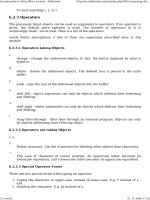
Organizations seek improved access control. Public
key certificates can be used to authenticate the identity of
version
serial number
signature
issuer
validity
issuerUniqueID
extensions
attributes
holder
Figure 6: X.509 attribute certificate structure.
a user, and this identity can be used as an input to access
control decision functions. In many contexts, however, the
identity is not the criterion used for access control deci-
sions. The access control decision may depend on role,
security clearance, group membership, or ability to pay.
Authorization information often has a shorter lifetime
than the binding of the subject identity and the public key.
Authorization information could be placed in a public key
certificate extension; however, this is not usually a good
strategy. First, the certificate is likely to be revoked be-
cause the authorization information needs to be updated.
Revoking and reissuing the public key certificate with up-
dated authorization information can be expensive. Sec-
ond, the CA that issues public key certificates is not likely
to be authoritative for the authorization information. This
results in additional steps for the CA to contact the author-
itative authorization information source.
The X.509 attribute certificate (AC) binds attributes to
an AC holder. Because the AC does not contain a public
key, the AC is used in conjunction with a public key certi-
ficate. An access control function may make use of the
attributes in an AC, but it is not a replacement for au-
thentication. The public key certificate must first be used
to perform authentication, then the AC is used to associate
attributes with the authenticated identity.
ACs may also be used in the context of a data origin
authentication service and a non-repudiation service. In
these contexts, the attributes contained in the AC provide
additional information about the signing entity. This in-
formation can be used to make sure that the entity is au-
thorized to sign the data. This kind of checking depends
either on the context in which the data is exchanged or on
the data that has been digitally signed.
Figure 6 illustrates an attribute certificate for Alice.
This is a version 2 AC, and the AC holder is Alice. The AC
was issued by the Hawk Data Attribute Authority, and was
signed with DSA and SHA-1. The serial number is 4801,
and the AC is valid from 8 a.m. on April 2, 2002, until
noon that same day. The attributes indicate that Alice
is VPN administrator. The AC extensions indicate that
this certificate is targeted toward the Hawk VPN server,
and that revocation information is not available for this
certificate. ACs often have no revocation information.
P1: JDW
PublicKey WL040/Bidgolio-Vol I WL040-Sample.cls June 19, 2003 16:56 Char Count= 0
PUBLIC KEY INFRASTRUCTURE (PKI)164
ACs may be short- or long-lived. In Figure 6, the AC per-
mits Alice to administer the VPN for 4 hours. As a result
of the short validity period, the AC issuer does not need to
maintain revocation information. By the time revocation
information could be compiled and distributed, the AC
would expire. So, with short-lived ACs, revocation infor-
mation is not distributed. If an AC has a longer life span
(for example, weeks or months), then the organizations
would need to maintain AC status information.
An AC can be obtained in two ways. The AC holder
may provide the AC; this is known as the push model.
Alternatively, the AC is requested from the AC issuer or a
repository; this is known as the pull model. A major benefit
of the pull model is that it can be implemented without
changes to the client or to the communications protocol.
The pull model is especially well suited to interdomain
communication.
The AC is linked to a public key certificate in one of
two ways. The AC holder can contain the issuer and serial
number of a particular public key certificate, or the AC
holder can contain a subject name. In the first case, the AC
is linked to a specific public key certificate. In the second
case, the AC is linked to a particular subject, and the AC
may be used in conjunction with any public key certificate
held by that subject.
FUTURE DEVELOPMENTS
One of the criticisms of PKI is that CRLs can become too
large. When this happens, the overhead associated with
CRL distribution is unacceptable. Sliding window delta
CRLs can be used to reduce this overhead. Another crit-
icism of PKI is that certification path construction and
validation can be difficult. By delegating these functions
to a trusted server, the amount of processing an applica-
tion needs to perform before it can accept a certificate can
be significantly reduced. Sliding window delta CRLs and
delegated path validation are not widely deployed today,
but they are likely to be employed in the future.
Sliding Window Delta CRLs
For PKIs that rely on CRLs, the challenge is to provide
the freshest information to certificate users while mini-
mizing network bandwidth consumption. Unfortunately,
when PKIs rely on full CRLs, these requirements are in
direct conflict. To maximize the freshness, CRLs must
be updated frequently. As the time interval between up-
dates shrinks, the probability that a client will find a use-
ful CRL in its cache diminishes. At the extreme, certifi-
cate users will download a full CRL for each certificate
validation. Most of the information on the CRL is the
same, and identical information is transmitted repeatedly,
consuming bandwidth without providing any benefit. To
minimize the consumption of network bandwidth, CRLs
should have reasonably long lifetimes. As the time inter-
val between updates grows, the greater the probability
that relying parties will have the appropriate CRL in their
cache.
In the simple case, delta CRLs and full CRLs are is-
sued together, and the delta CRL lists all the certificates
revoked since the last full CRL was issued. A certificate
user, who has the previous full CRL, may obtain complete
information by obtaining the delta CRL and combining
it with the already cached, previous full CRL. The certifi-
cate user obtains the freshest information available but
consumes a fraction of the bandwidth. If the certificate
user does not have the previous full CRL, the full CRL
must be downloaded.
A sliding window delta CRL lists all the certificates re-
voked since an earlier full CRL, perhaps six generations
earlier. This delta CRL may be combined with any of the
full CRLs from the previous six generations. By repeating
some of the revocation information in the delta CRL, there
is a greater likelihood that the certificate user will have an
acceptable full CRL in the cache, yet the amount of re-
peated information is small enough to avoid consuming
significant bandwidth.
Most of the PKI-enabled applications do not exceed
the limitations of full CRLs. As a result, delta CRLs are
not widely deployed. Few commercial PKI client imple-
mentations process delta CRLs. Fewer CA products can
generate sliding window deltas. As PKIs grow, however,
the incentive to deploy innovative certificate status will
likely grow.
Delegated Path Validation
Some PKI implementers want to offload the entire cer-
tification path construction and validation process to a
trusted server. A relying party would provide a validation
server with an end-entity certificate, one or more trust
points, and the initial values for certification path valida-
tion, then the path validation server would respond with
a message informing the relying party whether the certifi-
cate was acceptable. Standard protocols for these services
have not yet been developed. This work is currently un-
derway in the IETF PKIX Working Group.
Delegating the certificate validation process to a
trusted server has a number of advantages. The certifi-
cate user achieves path construction and validation with
a single roundtrip protocol, and then the certificate user
verifies a single digital signature on the response. The
single roundtrip is especially important in bandwidth-
limited environments, especially wireless environments.
If the certificate user has limited processing power, the
reduction in signature verifications is also significant.
Delegating the certificate validation process to a trus-
ted server may also provide performance advantages. If
the path validation server has cached the necessary cer-
tificates and CRLs, the path validation server may be able
to construct and validate a certification path quickly.
These benefits are not free. The path validation server
performs all of the security-relevant operations. The path
validation server must be secure, because it is the sole
trust point for the relying party. In addition, some of the
performance enhancements are based on the ability of the
server to obtain and cache information. PKIs that rely on
OCSP may be counterproductive to this model. In such a
case, the path validation server is not likely to hold the re-
quired status information. The server will have to retrieve
revocation information from the OCSP responder for each
certificate in the certification path, mitigating much of the
performance gain.
P1: JDW
PublicKey WL040/Bidgolio-Vol I WL040-Sample.cls June 19, 2003 16:56 Char Count= 0
FURTHER READING 165
Performance is not the only reason to centralize certifi-
cation path validation. Some organizations want impose
a centralized management discipline with consistent pol-
icy enforcement. If applications use the same trusted path
validation server, consistent results across the organiza-
tion are ensured.
GLOSSARY
Attribute authority An entity that is responsible for the
issuance of attribute certificates, assigning privileges to
the certificate holder.
Attribute certificate A data structure that is digitally
signed by an AA that binds attribute values with iden-
tification about its holder.
Certificate policy A named set of rules that indicates
the applicability of a certificate to a particular com-
munity or class of application with common security
requirements.
Certificate revocation list (CRL) A digitally signed list
of certificate serial numbers associated with a set of
certificates that are no longer considered valid by the
certificate issuer.
Certification authority An entity that is responsible for
the issuance of public key certificates, trusted by one
or more certificate users.
Certification practices statement A description of the
practices followed by a certification authority in issu-
ing and managing public key certificates.
Public key certificate A data structure that contains a
user identity, the user’s public key, and other informa-
tion, digitally signed by the CA.
Online certificate status protocol (OCSP) response A
digitally signed response from a trusted server that im-
plements the OCSP that provides status information
for a queried certificate.
CROSS REFERENCES
See Digital Signatures and Electronic Signatures; Elec-
tronic Payment; Guidelines for a Comprehensive Security
System.
FURTHER READING
Adams, C., & Farrell, S. (1999). Internet X.509 public
key infrastructure—Certificate management protocols
(RFC 2510). Retrieved March 2, 2003, from http://
www.ietf.org/rfc/rfc2510.txt
Adams, C., & Lloyd, S. (1999). Understanding public-key
infrastructure. Indianapolis, IN: Macmillan.
Chokhani, S., & Ford W. (1999). Internet X.509 public key
infrastructure—Certificate policy and certification prac-
tices framework (RFC 2527). Retrieved March 2, 2003
from />Cooper, D. (2000, May). An efficient use of delta CRLs. Pro-
ceedings of the 2000 IEEE Symposium on Security and
Privacy (pp. 190–202), Los Alamitos, CA: IEEE Com-
puter Society Press.
Housley, R. (2002). Cryptographic message syntax (CMS)
(RFC 3369). Retrieved March 2, 2003, from http://
www.ietf.org/rfc/rfc3369.txt
Housley, R., & Polk, T. (2001). Planning for PKI. New York:
Wiley.
Housley, R., Polk, W., Ford, W., & Solo, D. (2002).
Internet X.509 public key infrastructure—Certificate
and certificate revocation list (CRL) profile (RFC
3280). Retrieved March 2, 2003, from f.
org/rfc/rfc3280.txt
International Telecommunication Union-Telecommuni-
cation Standardization Sector (ITU-T). (2000). The
directory—Authentication framework (ITU-T Recom-
mendation X.509).
Kaliski, B. (1998). PKCS #7: Cryptographic message syntax,
version 1.5 (RFC 2315). Retrieved March 2, 2003, from
/>Kaliski, B. (1998). PKCS #10: Certification request syntax,
version 1.5 (RFC 2314). Retrieved March 2, 2003, from
/>Liu, X., Madson, C., McGrew, D., & Nourse, A. (2001,
September 11). Cisco Systems’ simple certificate en-
rollment protocol (SCEP) (work in progress). Re-
trieved March 2, 2003, from />draft-nourse-scep
Myers, M., Adams, C., Solo, D., & Kemp, D. (1999).
Internet X.509 certificate request message format
(RFC 2511). Retrieved March 2, 2003, from http://
www.ietf.org/rfc/rfc2511.txt
Myers, M., Ankney, R., Malpani, A., Galperin, S., &
Adams, C. (1999). X.509 Internet public key infras-
tructure—Online certificate status protocol (OCSP)
(RFC 2560). Retrieved July 30, 2002, from http://www.
ietf.org/rfc/rfc2560.txt
Myers, M., Liu, X., Schaad, J., & Weinstein, J. (2000).
Certificate management messages over CMS (RFC
2797). Retrieved from March 2, 2003, http://www.
ietf.org/rfc/rfc2797.txt
P1: IML/FFX P2: IML/FFX QC: IML/FFX T1: IML
Thompson2 WL040/Bidgolio-Vol I WL040-Sample.cls June 19, 2003 17:7 Char Count= 0
Public Networks
Public Networks
Dale R. Thompson, University of Arkansas
Amy W. Apon, University of Arkansas
Introduction 166
Overview of Public Network Concepts and
Services 166
Structure of the Public Switched Telephone
Network System 168
Access and Public Network Technologies 169
Voice-Grade Modems 169
Digital Subscriber Lines 169
Cable Modems 170
Satellite 171
Integrated Services Digital Network 171
Digital Leased Lines 171
Synchronous Optical Network 172
X.25 172
Frame Relay 172
Asynchronous Transfer Mode 172
Choosing a Private Network or
a Public Network Provider 173
Reliability 174
Cost and Performance Tradeoffs 174
Support 174
Control 174
Other Factors 175
Public Networks in the Internet and E-commerce
Environments 175
Conclusion 175
Glossary 176
Cross References 176
References 176
INTRODUCTION
Networks for the transfer of data between computers,
both public and private, are ubiquitous in today’s busi-
ness world. A public network is one that is publicly avail-
able to subscribers (Stallings, 2001). It provides service
to multiple subscribers and is built and maintained by a
public network provider. Internationally, the term “pub-
lic network” is often applied to networks that are under
government control or are a national monopoly. However,
a network can also be a privately owned network whose
services are sold to the public. Whether the network is un-
der government control or is a privately owned network
whose services are sold to the public, businesses access
the network by installing an access device at each site and
using an access line to the nearest point of presence (POP)
of the public network provider (Panko, 2001).
This chapter gives an overview of public network con-
cepts and services and describes the structure of the public
switched telephone network (PSTN) system, the technolo-
gies used both for access to a public network and within
the public network itself, issues related to choosing a pub-
lic or a private network, and public networks in the Inter-
net and e-commerce environments.
OVERVIEW OF PUBLIC NETWORK
CONCEPTS AND SERVICES
Traditionally, companies desiring to connect business
computers in different geographic locations have used
private networks. That is, they have used point-to-point
leased lines between business sites to create their own
circuit-switching or packet-switching networks for their
data communication requirements (Panko, 2001). Unlike
telephone calls, which set up the required capacity as
needed, leased lines provide dedicated transmission ca-
pacity between sites. These networks are called private
networks (Stallings, 2001). By using leased lines, compa-
nies have a network capacity that is always available and
are offered volume discounts for the bandwidth available
on the leased line. An example of a private network is
shown in Figure 1.
There are several disadvantages to private networks.
Private networks require higher initial costs. The leased
line connections must be planned and installed. The
switching devices must be provided. And, once a network
is operational there are ongoing management and main-
tenance costs of the networks (Panko, 2001). A public net-
work is an alternative to a private network.
There are advantages to using a public network. A pub-
lic network does not require a complex network of leased
lines and switching devices that the business must plan
and install. There is commonly one access line installed
per site. Even if a leased line is used to connect to the
nearest POP, there are usually less leased lines required.
For example, if there are 10 sites using the public net-
work, then there are 10 leased lines. Compare this to a
fully meshed private network that requires 45 leased lines.
For N locations, N(N − 1)/2 leased lines are required for
a connection to and from each site. Even if not every site
is connected to every other site in the private network, but
sites are connected through intermediate sites, the num-
ber of leased lines for a public versus a private network is
generally smaller. Finally, because of competitive pricing,
public networks are less expensive than private networks
(Stallings, 2001). Figure 2 illustrates an example of a pub-
lic network.
The global Internet is a network that is publicly acces-
sible worldwide. The Internet is not one single network,
but is composed of several networks connected together
and communicating with standard Internet technologies
(Moody, 2001). Access to the Internet is achieved via an
Internet service provider (ISP). The Internet allows a busi-
ness to have a worldwide presence. Through the use of
166
P1: IML/FFX P2: IML/FFX QC: IML/FFX T1: IML
Thompson2 WL040/Bidgolio-Vol I WL040-Sample.cls June 19, 2003 17:7 Char Count= 0
OVERVIEW OF PUBLIC NETWORK CONCEPTS AND SERVICES 167
56 Kbps
Leased Line
Site A
Site B
Site C
Site D
56 Kbps Leased Line
56 Kbps
Leased Line
T1 Leased Line
56 Kbps
Leased Line
56 Kbps
Leased Line
Site E
T1 Leased Line
Figure 1: A private switched data network.
E-commerce purchases can be made automatically with
software.
A network that transfers data and information only
within a single business is called an intranet (Moody,
2001). Intranets use the same technologies as the Internet
but access is restricted to employees. They carry corporate
information that can range from being routine such as
e-mail, manuals, and directories or can be sensitive infor-
mation such as that of project management and internal
purchasing. An intranet can be built using a private or a
public network. A private network is naturally an intranet.
A business using a public network can ask that the data be
restricted to only go to other locations of the same busi-
ness. Of course, the bandwidth is still being shared with
other businesses that use the same public network.
An extranet is a hybrid between the public Internet and
the private intranet (Moody, 2001). A portion of the in-
tranet is extended to business partners in a controlled and
restricted way. The extranet can be used for project man-
agement of projects between partners. Another common
and practical use of the extranet is to allow partners access
to the stock levels and shipping status. Direct online pur-
chasing of supplies and other applications are made pos-
sible through the use of an extranet.
The global Internet can be used to provide an intranet
or an extranet by creating a virtual private network (VPN).
A VPN is a private network that is deployed over public
facilities, but provides the same levels of privacy, security,
quality of service, and manageability as private networks
(Cisco, 2001).
A VPN can be created when all sites are already con-
nected to the Internet. With a VPN, hosts at different
sites communicate across the Internet using either a tun-
nel mode between local networks, or by using a direct
transport communication. However, there are two serious
problems that can occur with VPNs since the company
no longer has control of the entire data network (Panko,
2001). One problem is the security of the data, because the
Internet was not designed to support secure transmission.
This problem can be solved through the use of encryption
and by using tunnel mode for communication. A second
problem is congestion on the Internet. Congestion can
T1 Leased
Line
Site A
Site B
Site C
Site D
T1 Leased Line
56 Kbps
Leased Line
Site E
T1 Leased Line
Public
Switched Data
Network
T1 Leased
Line
Figure 2: A public switched data network.
P1: IML/FFX P2: IML/FFX QC: IML/FFX T1: IML
Thompson2 WL040/Bidgolio-Vol I WL040-Sample.cls June 19, 2003 17:7 Char Count= 0
PUBLIC NETWORKS168
cause data to be delayed or even lost. A VPN uses a public
network for site-to-site communication and added tech-
nology to solve the problems of security and congestion
(Panko, 2001).
A public network provider has a value-added network
if it owns the packet-switching nodes and leases trans-
mission capacity from an interexchange carrier such as
AT&T (Stallings, 2001). It is called a value-added network
because the leased lines add value to the packet switching
nodes. A network provider that provides a value-added
network is sometimes called a value-added carrier. In
many cases a public network provider will partner with
companies that provide services that require network con-
nectivity such as Web hosting and give discounts to them
for using their network. A business which bundles a ser-
vice with a particular public network provider is called a
value-added reseller.
Public network providers often offer services such
as Web hosting to subscribers in addition to connectiv-
ity between sites. These additional services are called
value-added services. These services include asset man-
agement, configuration control, fault management, moni-
toring, Web-based reporting, Web hosting, e-mail services,
and content delivery networks.
Asset management is keeping inventory of devices that
are connected to the network. As devices are added or
taken off the network the asset management system will
keep an up-to-date log of the assets. Configuration control
is about maintaining and keeping records of the configu-
ration of networked devices. The network provider typi-
cally maintains the configuration of the packet switching
node that connects each of the subscriber locations to the
network. A provider will also monitor devices to detect
faults and either fix them or notify the appropriate on-site
personnel. This is called fault management. A provider
can invest in large network operation centers for moni-
toring their subscribers’ network devices. This includes
maintaining a firewall to prevent unwanted users into
the network and intrusion detection systems for detect-
ing activity that is consistent with common hacker tech-
niques. With Web-based reporting the provider gives the
subscriber reports about the status of their network and
a history of its downtime and performance.
One of the most popular value-added services is Web
hosting. The provider maintains one or more servers and
allocates space on them for the subscriber’s Web site. The
provider maintains the server and performs backups. Sub-
scribers are given access to their portions of the server to
post their Web sites and control their content. An advan-
tage to using this value-added service is that it is likely
that the subscriber has other sites that are connected to
the same public network. If the server is connected to the
same public network, it provides faster response times to
the end users.
Medium to large users who have high volumes of
content serving a distributed set of users may consider
a value-added service called a content delivery network
(CDN). A CDN intelligently distributes the content to mul-
tiple locations and closer to the end user. By moving the
customized content closer to the end user the end user
receives faster response times (Allen, 2001). Queries to
the main server or group of servers are routed to the
location that can best respond to the query. Content is
cached at each of the locations and future requests are
serviced more quickly because the information traverses
fewer links in the network. There are three main advan-
tages to a CDN. First, end users receive faster response
times. Second, it relieves congestion on the original server
that maintains the master copy of the content. Finally,
it reduces the amount of data transmission capacity re-
quired on the network since the content is distributed
to multiple locations and does not have to come from
the original server. Some of the popular CDN providers
are Akamai () and Mirror Image
().
STRUCTURE OF THE PUBLIC
SWITCHED TELEPHONE
NETWORK SYSTEM
The public switched telephone network system is often
used to provide the technology that a business uses to
access a public network or is the technology of the public
or private lines. The structure of the PSTN in the U.S.
has evolved from one that was almost entirely controlled
by a single company to one that allows competition in a
free market. Before January 1, 1984, AT&T (also known
as the Bell System) controlled 80% of the PSTN in the
U.S. (Bellamy, 2000). A Justice Department antitrust suit
filed in 1974 and a private antitrust case by MCI resulted
in a breakup of AT&T (Noam, 2001). The suit argued that
AT&T used its control of the local operation as an unfair
advantage against competing long distance carriers.
On January 1, 1984, AT&T was divided into smaller
companies. The breakup involved the divestiture of seven
Bell operating companies (BOCs) from AT&T. The seven
regional BOCs were known as “Baby Bells” or regional
BOCs (RBOCs) and initially carried only regional tele-
phone and mobile service. The network was partitioned
into two levels (Bellamy, 2000), and the remaining part of
AT&T retained the transport of long distance telephone
service.
The U.S. was divided into local access and transport
areas (LATAs), which are controlled by local exchange car-
riers (LECs). LECs can transport telephone calls within a
LATA, also called intra-LATA traffic, but are not permitted
to transport traffic between different LATAs, also called
inter-LATA traffic, even though the same BOC may con-
trol both LATAs. The inter-LATA traffic is transported by
interexchange carriers (IXCs), commonly known as long
distance carriers. Each IXC interfaces at a single point
in the LATA called a point of presence. At divestiture,
AT&T became an IXC and it opened the door to competi-
tion for other companies’ long distance service. The ma-
jor IXCs in the U.S. include AT&T, MCI–WorldCom, and
Sprint.
The divestiture decree was supervised by District Judge
Harold Greene and known as the modified final judgment
(Noam, 2001). LECs had to grant equal access to all IXCs.
The service offered by the LECs to the IXCs had to be
equal in type, quality, and price (Bellamy, 2000). Also,
users could specify their “primary” IXC to transport their
long distance and international calls (Noam, 2001). Or,
P1: IML/FFX P2: IML/FFX QC: IML/FFX T1: IML
Thompson2 WL040/Bidgolio-Vol I WL040-Sample.cls June 19, 2003 17:7 Char Count= 0
ACCESS AND PUBLIC NETWORK TECHNOLOGIES 169
users could use other IXCs on a call-by-call basis by dial-
ing a prefix.
Another major change in the U.S. PSTN occurred with
the 1996 Telecommunications Act that amended the Com-
munications Act of 1934 (Noam, 2001). RBOCs had to
comply with a list of tasks before they were permitted to
provide long-distance service within their regions. The list
permitted competition in the RBOCs regions. It was ar-
gued that it was necessary to induce competition in these
local markets. RBOCs were required to provide intercon-
nection to new market competitors, unbundle their net-
work, permit competitors to resell their service, and pro-
vide users with number portability.
The new local service providers became known as
competitive local exchange companies (CLECs) (pro-
nounced “see-lecks”) (Noam, 2001). The incumbent LECs
became known as ILECs. For a CLEC to be competitive
with the ILEC requires that it be able to interconnect
with the users cost effectively. Therefore, there came a
great struggle between CLECs and ILECs on the issue of
collocation since the ILEC had a significant advantage
with the existing network. In “physical collocation”
a CLEC places its cables and equipment inside the
ILEC’s central office (CO) to hand off traffic. In another
arrangement called “virtual collocation” the physical
handoff of the traffic occurs inside or outside the CO, but
uses ILEC-owned equipment and must be the economic
equivalent of “physical collocation.”
It may appear from the previous discussion that the
breaking up of the U.S. PSTN is relevant only to the United
States but the trend is happening in other parts of the
world as well (Noam, 2001). Japan opened its markets
to competition. Also, the Europeans have privatized their
service. Noam argues that at first a network is not feasi-
ble unless supported by outside sources such as govern-
ments. As the network grows the average costs decline
initially and then rise as a few high-cost users are added.
Without regulation the network would not grow beyond
a certain point because of the high cost of adding these
high-cost users. From a political and societal point of view
the network becomes a necessity instead of a convenience
and should be offered to everyone. Therefore, the monop-
olistic breakdown of the network is caused by its own
success.
ACCESS AND PUBLIC NETWORK
TECHNOLOGIES
To use a public network for data services, a user must
access the public network through some network service
from the user’s computing equipment to the nearest pub-
lic network node. Factors in selecting a particular service
include the cost of the service that is provided and the fea-
tures, including the transmission speed, that are provided
by the technology. Generally, the higher the transmission
speed that a technology can support, the more costly the
service becomes. Transmission speeds for networks are
described in bits per second. Unlike when memory size is
described, 1 Kbps is exactly equal to 10
3
bits per second,
1 Mbps is exactly equal to 10
6
bits per second, and 1 Gbps
is exactly equal to 10
9
bits per second.
Many technologies are available for access to a public
network and for use within the public network. The most
inexpensive network access is through a voice-grade mo-
dem. A modem is used to convert a digital computer signal
to an analog signal that can be sent across ordinary tele-
phone lines. Voice-grade modems can receive data at up to
56 Kbps. In contrast, digital lines that are used to access
the network range in transmission speed from 56 Kbps
to 10 Gbps. Within the public network a few technolo-
gies, including X.25, frame relay, asynchronous transfer
mode (ATM), and synchronous optical network (SONET),
have become the most commonly used technologies.
Table 1 lists the most common technologies along with
a comment about usage. Table 1 also compares the trans-
mission speed and the time to download a 10-megabit
(1.2 Megabyte) file.
Voice-Grade Modems
A modem is the most inexpensive and easiest to use access
technology. The use of modems for data transmission will
be substantial for many years to come (Stallings, 2001).
Voice-grade modems use a 4-KHz bandwidth on an ordi-
nary telephone line, the same bandwidth that is used for
voice signals. Modems can be packaged inside an infor-
mation product, such as a personal computer. Companies
often have modem banks that allow employees to dial-in
directly to the company intranet or to access a large com-
puter system.
On March 1, 1993, the International Telecommunica-
tions Union (ITU) Telecommunications Standardization
Sector (ITU-T) was created as a permanent organ of the
ITU, an agency of the United Nations. The charter of
the ITU-T is to standardize techniques and operations in
telecommunications. Several standard specifications for
voice-grade modems have been designated by the ITU-T.
Two of the most significant modem specifications are V.32,
which is a dial-up modem that transmits at 9600 bps, and
V.90, also a dial-up modem. V.90 sends at 33.6 Kbps and
receives at 56 Kbps, the highest rates available for voice-
grade modems (Stallings, 2001).
Digital Subscriber Lines
A faster service than voice-grade modems that is begin-
ning to be offered by telephone companies is the digital
subscriber line (DSL). A widely publicized version of this
is asymmetric digital subscriber line (ADSL). ADSL offers
high-speed downstream access to the customer site, and
a lower speed upstream access from the customer. The
ITU-T has developed a standard for low-speed ADSL
called G.992.2, or G.Lite. G.Lite specifies downstream
speeds of 1.5 Mbps, but sometimes lower downstream
speeds are used. Most users find asymmetric speeds to be
acceptable, since upstream traffic frequently consists of
keystrokes or the transmission of short e-mail messages,
whereas downstream traffic may include Web pages, or
large amounts of data. In addition to data speed, an advan-
tage of DSL over voice-grade modems is that DSL modems
allow voice traffic to be multiplexed onto the telephone
wires coming into the customer site. A customer can talk
on the telephone at the same time that data are being
transferred.
P1: IML/FFX P2: IML/FFX QC: IML/FFX T1: IML
Thompson2 WL040/Bidgolio-Vol I WL040-Sample.cls June 19, 2003 17:7 Char Count= 0
PUBLIC NETWORKS170
Table 1 Common Network Technologies
Service Usage Comments Transmission Speed Download
Voice-Grade Modem Modems are inexpensive, telephone
rates reasonable for modest
connect times
Upload: Up to 33.6 Kbps
Download: Up to 56 Kbps
3 min or more
Digital Subscriber Line More expensive than voice-grade
modems, downlink rates higher
than uplink
Upload: From 16 Kbps to 640 Kbps
Download: From 768 Kbps to
9 Mbps
1.1–13 s
Cable Modems Download rates depend on the
number of simultaneous
customers and configuration
Upload: From 64 Kbps to 256 Kbps
Download: From 10 Mbps to
30 Mbps
0.3–1 s
Satellite A cost-effective choice in remote
locations
Upload: From 56 Kbps to 256 Kbps
Download: From 150 Kbps to
1 Mbps
10–67 s
Integrated Services
Digital Network
Charges generally based on
duration of call
Basic rate: 128 Kbps, higher rates
available
1.3 min
Digital leased lines:
56 Kbps (DS0), T1
(DS1), T3 (DS3), . . .
Most common leased line for
high-traffic voice and data; fixed
price for a specific capacity
DS0: 56 Kbps T1, DS1: 1.54 Mbps
T3, DS3: 44.7 Mbps
56 Kbps: 3 min
T1: 6.5 s
T3: 0.22 s
SONET Specification for optical links,
highest speed
From 155.52 Mbps to 2.488 Gbps
leased
0.004–0.06 s
X.25 Older technology, still in use in
public networks
56 Kbps, but can be slower or faster 3 min or more
Frame Relay Fixed price per month for a specific
capacity, widely installed and
used
From 16 Kbps to 44.736 Mbps 0.22–625 s
ATM Universal technology for wide area
networking
From 1.544 Mbps to 2.5 Gbps for
access
0.004–6.5 s
The telephone company does not have to install any
special equipment to use voice-grade modems. However,
when the telephone company offers DSL service it has to
install digital subscriber line access multiplexers at the
end offices. Figure 3 illustrates the equipment used for
DSL (Panko, 2001). Because special equipment has to be
installed, DSL service is not available in all areas. One fac-
tor that determines the availability of ADSL is the distance
to the central office. In general, if the distance is greater
than 18,000 feet ADSL service is not available. Also, the
prices are fluctuating as DSL becomes available in more
and more areas.
Cable Modems
Cable modems are a service offered by cable televi-
sion companies. Often, the cable television or telephone
All digital
internally
Single twisted pair,
ordinary telephone
line
DSL Modem
DSU for computer
Codec for telephone
Telephone Company
Service Provider
Digital leased line
,
Megabit speeds
DSL Access
Multiplexer
Figure 3: Asymmetric digital subscriber line. Source: Buisness Data Communications and Net-
working, 3/E (Panko, 2001). Reprinted by permission of Pearson Education Inc., Upper Saddle
River, NJ.
P1: IML/FFX P2: IML/FFX QC: IML/FFX T1: IML
Thompson2 WL040/Bidgolio-Vol I WL040-Sample.cls June 19, 2003 17:7 Char Count= 0
ACCESS AND PUBLIC NETWORK TECHNOLOGIES 171
company operates as both a transmission carrier and a
network provider. As with ADSL, the downstream speed
of cable modem is much faster than the upstream speed.
The upstream speeds are similar to ADSL, but the down-
stream speeds can be several times faster. However, mul-
tiple customers on the same cable line share the capacity.
When many customers are accessing the network at the
same time the real downstream transmission speed can
be much lower. If network traffic is bursty, though, the
chances are unlikely that all customers are downloading
at exactly the same moment so that sharing does not be-
come as issue until about 100 customers share the same
cable service (Panko, 2001).
Satellite
An often cost-effective alternative for network access is
the use of satellite technology. This may be particularly
true in areas where other wire-based technologies are not
yet available. For example, many rural areas do not have
the density of potential users that can justify the cost of in-
stallation of wire-based technologies such as DSL or cable
modems.
Satellites are characterized by the type of orbit they
use. The most common type of satellite is the geosta-
tionary satellite. These satellites orbit the Earth at about
22,300 miles directly above the equator at exactly the same
speed as the Earth’s rotation. Because of this, the satellite
always appears to be in the same position in the sky and
tracking of the satellite by stations on Earth is simplified
(Stallings, 2001). The disadvantage of this type of satel-
lite is that the propagation time it takes for the signal to
be sent from a transmission station on the Earth to the
satellite, and then to be received back on the Earth is about
0.24 s. For large data downloads this is not noticeable
since the time overlaps with the time to receive the en-
tire message. However, for interactive computer use or
for applications such as telephone calls the time is no-
ticeable and can be annoying. In addition, geostationary
satellite signals are not received well in very far northern
or southern regions of the Earth.
Two other types of orbits include low- and medium-
Earth orbiting satellites. This technology is being pro-
posed for use with mobile terminals and remote loca-
tions that need stronger signals and less propagation time.
Successful businesses that use this technology are rare.
One company currently operating under bankruptcy reg-
ulations, Iridium, provides global, mobile satellite voice
and data solutions with complete coverage of the Earth
through a constellation of 66 low-Earth orbiting satellites
(Iridium, 2002).
Large satellite dishes create narrow footprints for
transmission, and large dishes are used for point-to-point
trunk transmissions. A small dish creates a very large
footprint that is suitable for television broadcasts in a
large region. Today, very small aperture terminal systems
are available and provide a low-cost alternative to expen-
sive point-to-point satellite connections. These stations
share satellite transmission capacity for transmission to
a hub station (Stallings, 2001).
Satellite access has some advantages over wire-based
technologies. The technology is available now for all loca-
tions in the United States, whereas DSL and cable modem
technologies may not be available in some locations for
some time. For the speeds and services available the tech-
nology is cost-competitive. However, in order to use satel-
lite, the user must have a clear view of the southern sky.
The uploads speeds are modest, so satellite is not suit-
able for businesses that require high-upload bandwidth
for applications such as large upload data transfers or for
hosting Web sites. Also, the download bandwidth is shared
with all users at the site, and so the technology is not cur-
rently suitable for more than five simultaneous users.
At least one company offers packages with two-way,
always-on, high-speed Internet access via satellite that
is specifically designed to meet the needs of small busi-
nesses (StarBand, 2002). StarBand uses a 24-by-36-inch
dish and a special modem at the customer’s site to con-
nect the user’s site to the network. StarBand also serves as
a network provider. Fees include an initial equipment fee
and a monthly fee for access. Value-added services such
as domain registration and networking support for setting
up small office networks can be a part of the package.
Integrated Services Digital Network
Many telephone companies offer integrated services dig-
ital network (ISDN), a digital service that runs over or-
dinary telephone lines. As with voice-grade modems the
ITU-T has set standards for ISDN. ISDN can be used as
an access technology and within a public network. Basic
ISDN service includes two “B” channels, each at 64 Kbps,
and a “D” channel that is used for signaling. It is possible
to use one “B” channel for voice and one for data, but most
service providers bond the two “B” channels together to
provide a 128 Kbps data rate. Standards for higher rates
also exist. Like ADSL, ISDN requires that the telephone
company install special equipment at the end office before
an ISDN service can be offered. A special ISDN “modem”
is used at the customer site.
ISDN is the result of efforts in the early 1980s by
the world’s telephone companies to design and build a
fully digital, circuit-switched telephone system (Tanen-
baum, 1996). Because ISDN is circuit-switched, there is
never any congestion on the line from the customer to
the network service provider. However, since data traffic
is generally bursty the user pays for bandwidth that may
not be used. ISDN is expensive compared to the modest
gain in transmission speed. The customer generally has to
pay for the ISDN line to the telephone company and then
has to pay an additional fee to a network service provider.
The use of ISDN is likely to decline as other higher speed
and more economical technologies become available.
Digital Leased Lines
In terms of number of circuits, the most common leased
lines are 56 Kbps (Panko, 2001). The transmission capac-
ity of a 56 Kbps is actually 64 Kbps but one bit out of
eight is used for signaling, leaving the user with 56 Kbps.
A 56 Kbps line is the same as digital signal zero (DS0).
The next higher transmission speed is a T1 (DS1), which
provides 1.544 Mbps. While a 56 Kbps leased line is rela-
tively inexpensive, the difference in cost and performance
between a 56 Kbps and a T1 line is large. Therefore, frac-
tional T1’s are also available at 128 Kbps, 256 Kbps, 384
Kbps, and so on. In Europe and other parts of the world
P1: IML/FFX P2: IML/FFX QC: IML/FFX T1: IML
Thompson2 WL040/Bidgolio-Vol I WL040-Sample.cls June 19, 2003 17:7 Char Count= 0
PUBLIC NETWORKS172
a different digital hierarchy of transmission capacities is
used. The standards are defined in the Council of Euro-
pean Postal and Telecommunications authorities (CEPT).
The E1 standard operates at 2.048 Mbps and is analogous
to the T1 standard. The next step is a T3 (DS3) at 44.7
Mbps and the corresponding CEPT E3 standard operating
at 34.4 Mbps. Higher transmission capacities are available
using synchronous optical network (SONET) and the syn-
chronous digital hierarchy (SDH) and range from 155.52
Mbps to 10 Gbps.
Digital leased lines can be used to build a company’s
leased line private network, as shown in Figure 1, or can
be used in combination with a public network, as shown
in Figure 2. When leased lines are used to access a public
network the traffic between several sites must be multi-
plexed over the single access line. Therefore, it is impor-
tant to be sure that the leased line is fast enough to support
this traffic. For example, if a site has 15 56 Kbps leased
lines connected point-to-point with other sites and wants
to convert this to a single access line to a public network,
then the access line would require at least 840 Kbps of ca-
pacity. From Table 1, this would require a T1 line (Panko,
2001).
Synchronous Optical Network
Synchronous optical network defines a hierarchy of stan-
dardized digital data rates. A compatible version, Syn-
chronous digital hierarchy has been published by the
ITU-T. SONET is intended to provide a specification for
high-speed digital transmission over optical fiber.
SONET, or SDH, is the highest speed and most
costly digital leased lines. SONET/SDH operates in mul-
tiples of 51.84 Mbps. Standards are specified as OCx for
SONET, and STMx for the SDH specification. A common
SONET/SDH speed is OC3/STM1, at 156 Mbps. Other
common rates include 622 Mbps, 2.5 Gbps, and 10 Gbps.
SONET technology can be used for access both to the pub-
lic network and within the public network.
X.25
X.25 was developed during the 1970s for use in public
packet switching networks, and this standard was later
ratified by the ITU-T (Tanenbaum, 1996). X.25 was very
slow, often running at only 9600 bps, but it was fast
enough for the text-based transmissions of early net-
works. Its use is declining, but it is still popular in the U.S.
for low-speed applications such as a department store’s
point-of-sale transaction network. Also, there are many
X.25 legacy connections, particularly in Europe and in
countries where the telecommunications infrastructure is
lagging. X.25 is one of a few standards that have been set
by the ITU-T for public switched data networks. Other
standards set by the ITU-T for public networks include
ISDN, frame relay, and ATM.
Frame Relay
Frame relay is the most popular technology choice within
public switched data networks today (Panko, 2001). Its
speed range matches the needs of the greatest corporate
demand, and it has very competitive pricing. Frame relay
can also be used instead of leased lines as an access tech-
nology or to connect company private networks. Its low
overhead even makes it suitable for interconnecting LANs
and high-speed stand-alone systems (Stallings, 2001). Cur-
rent commercial offerings of frame relay include MCI–
WorldCom, which offers frame relay service access speeds
from 28.8 Kbps to 45 Mbps (MCI–WorldCom, 2002), and
Qwest, which offers frame relay service access speeds
from 64 Kbps to 45 Mbps (Qwest, 2002).
Typically, a company accesses a public frame relay net-
work through a leased line. Several frame relay virtual
circuits are multiplexed over a single access line to the
public network. A virtual circuit is a connection from
source to destination and represents an end-to-end path
that all packets from the same source to the same destina-
tion go through. Virtual circuits simplify forwarding de-
cisions and make the costs of the switches cheaper. A per-
manent virtual circuit (PVC) is one that is set up manually
when a company first subscribes to a public network, and
only changes when the site changes. For a large company
network, a PVC is established for every pair of sites that
would get a leased line in a private leased line network.
The frame relay protocol includes functions for detec-
tion of transmission errors and congestion control func-
tions. The frame relay protocol allows users to negotiate
a committed information rate (CIR) when a connection
is set up. The CIR is the network’s commitment to deliver
data in the absence of errors, and represents the user’s
estimate of its “normal” traffic during a busy period. Any
traffic sent above the CIR is not guaranteed to arrive, but
may arrive if the network has the capacity to deliver it.
In addition, a maximum allowable rate is defined, and all
traffic above this level is discarded (Frame Relay Forum,
2002).
Pricing for frame relay is usually divided into several
different components. First, the company needs a frame
relay access device. This is a router that has been modi-
fied to allow it to communicate with the frame relay’s first
switch. Second, the company must lease an access line
to the nearest POP of the public network. If the POP is
a long distance away then the customer must use expen-
sive, long-distance access lines. The leased line must be
fast enough to handle the available bit rate on the line.
At the POP, the leased access line connects to a port on
the frame relay switch of the public network. The fee for
the port is usually the largest single element in frame re-
lay pricing. To prevent wasting port capacity, the speed of
the leased line should be at least as fast as the port speed.
There is usually a monthly fee for each PVC and this fee
depends on the speed of the PVC. Finally, some vendors
build in other fees, such as per-bit traffic charges or fees to
set up and tear down switched virtual circuits that are es-
tablished on a call-by-call basis. Frequently there are sub-
stantial initial charges to install the access device, leased
line, port connection, or PVC. Figure 4 illustrates the pric-
ing elements in frame relay (Panko, 2001).
Asynchronous Transfer Mode
Asynchronous transfer mode is now viewed to be the
universal technology for networking and will likely re-
place many other current offerings (Stallings, 2001). Just
as frame relay allows messages to be divided into many
P1: IML/FFX P2: IML/FFX QC: IML/FFX T1: IML
Thompson2 WL040/Bidgolio-Vol I WL040-Sample.cls June 19, 2003 17:7 Char Count= 0
CHOOSING A PRIVATE NETWORK OR A PUBLIC NETWORK PROVIDER 173
5. Sometimes
Traffic
Charges and
Other
Charges
2. T1 Leased Access
Line to POP
Customer Site B Customer Site C
Customer Site A
1. Access Device
POP
CIR=56 Kbps
Switch
Switch
Switch
PVC 2
PVC 1
4. PVC
Charges
Public Switched Data Network
3. Port
Speed
Charge
PVC 1 and PVC 2, multiplexed
PVC 2
PVC 2
PVC 1
Figure 4: Pricing elements in frame relay services. Source: Buisness Data Communications and Net-
working, 3/E (Panko, 2001). Reprinted by permission of Pearson Education Inc., Upper Saddle River,
NJ.
frames that can be sent across a switched network, ATM
uses cell relay. Like frame relay, ATM multiplexes many
logical connections over the same physical interface,
sending information in fixed size 53-byte cells. ATM can
support data, video, voice, and Internet traffic on a single
access line.
The use of cells in ATM allows many important features
to be defined for a virtual channel. For example, users
can negotiate the ratio of cells lost to cells transmitted,
cell delay variation and parameters such as the average
rate, peak rate, burstiness, and peak duration for a virtual
channel (ATM Forum, 2002). The ATM service can use per-
manent virtual channels for static connections. ATM also
allows switched virtual channels to be set up dynamically
on a call-by-call basis.
Four classes of ATM service have been defined
(Stallings, 2001):
Constant bit rate: The network provider ensures that this
rate is available, and the customer is monitored to be
sure the rate is not exceeded.
Variable bit rate (VBR): A sustained rate for normal use
is defined, and a faster burst rate for occasional use
is also defined. The faster rate is guaranteed, but not
continuously. The ATM Forum divides VBR into real-
time VBR (rt-VBR) and nonreal-time VBR (nrt-VBR)
(ATM Forum, 2002). With rt-VBR the application has
tight constraints on delay and delay variation, but the
rate is allowed to vary according to parameters spec-
ified by the user. The nrt-VBR is for applications that
are bursty, but do not have tight constraints on delay
and delay variation.
Available bit rate (ABR): The user has a guaranteed min-
imum capacity. When additional capacity is available
on the network, the user may burst above this without
risk of cell loss.
Unspecified bit rate (UBR): Cells are delivered with best
effort, meaning that any cell may be lost. The main
difference between UBR and ABR is that ABR provides
feedback to the user so that the user can control the
amount of data being sent and reduce the risk of loss.
ATM is a high-performance service and is expensive.
In the range of speeds where ATM speeds overlap with
frame relay, frame relay is more attractive because it is
cheaper. However, as customer needs increase, ATM be-
comes a more attractive option. ATM is widely used within
high-speed public networks and by companies that need
higher speed private networks. Most ATM public switched
data network providers currently offer speeds from 1
Mbps to 156 Mbps, with higher speeds coming. These
public networks require access lines ranging from T1 to
a SONET OC-3 line. MCI–WorldCom offers ATM access
speeds from 1.544 Mbps to 622 Mbps (MCI–WorldCom,
2002). Qwest offers ATM access speeds from 1.544 Mbps
to 155 Mbps (Qwest, 2002).
CHOOSING A PRIVATE NETWORK OR
A PUBLIC NETWORK PROVIDER
There are several categories to consider when one decides
whether to use a private network or a public network. If
a public network is chosen, then these same categories
can help in choosing a network provider. A survey ISPs
conducted in 2001 found that the top three areas that dif-
ferentiated the best ISPs from the rest were reliability, per-
formance, and low cost (Greenfield, 2001). Subscribers to
ISPs in the survey also considered support to be impor-
tant. In addition, network control is a factor in deciding
whether to choose a private network or a public network.
Other factors mentioned in the survey include breadth of
service, security, installation, repairs, and remote access.
P1: IML/FFX P2: IML/FFX QC: IML/FFX T1: IML
Thompson2 WL040/Bidgolio-Vol I WL040-Sample.cls June 19, 2003 17:7 Char Count= 0
PUBLIC NETWORKS174
Reliability
Reliability is defined as the amount of time the network
service is available. Reliability can be difficult to evaluate
because several different things can cause downtime. For
example, if a user is trying to transfer data from a server
that is down then from the user’s point of view the net-
work is down. When a packet switching node or dedicated
leased line in a large complex network does fail it affects
a large amount of transmission capacity and therefore
a large number of users. For example, MCI–WorldCom’s
frame relay outage in August 1999 lasted eight days and
affected 30% of MCI’s frame relay customers, perhaps as
many as 70,000 users (Orenstein and Ohlson, 1999).
An advantage to using a private network is that the
redundancy of the network can be designed according
to the business requirements. The major disadvantage is
that it requires investment in redundant packet switch-
ing nodes and leased lines for fault tolerance, personnel
training, disaster recover planning, and testing. These ex-
penses are often overlooked or have less priority when a
private network is designed (Snow, 2001). Or once the pri-
vate network is operational these expenses are considered
low priority. Therefore, when there is an outage the busi-
ness is not prepared for it and its effects are worse than if
a disaster recovery plan had been written.
The reliability of a public network has advantages and
disadvantages. The advantage of using a public network
is that since the cost is spread out over several subscribers
added investment in reliability can be cost effective. The
disadvantage is that a subscriber is completely dependent
on the provider for reliable service. Service level agree-
ments have to be negotiated with clear and strict penalties
if the provider does not meet the negotiated reliability. If
reliability is of high importance to a business, then they
may subscribe to two or more public network providers
for added reliability.
Cost and Performance Tradeoffs
The choice between a public and private network includes
determining the tradeoffs between the cost and perfor-
mance of the network. The performance of the network
is defined by throughput and delay. The throughput is the
actual data speed seen by the user in bits per second. The
delay is the maximum end-to-end delay that a packet will
incur in the network.
The costs of the network may vary depending on the
type and volume of traffic that the network will carry. The
type of traffic on a network is classified as being either
stream or bursty (Stallings, 2001). Stream traffic is long
and relatively constant and therefore more predictable
than bursty traffic. An example of stream traffic would be
voice traffic or uncompressed video. Bursty traffic is short
and sporadic such as computer-to-computer communica-
tion in the Internet. Although sporadic, bursty traffic often
requires a large transmission capacity for brief periods of
time. Many Internet applications such as the Web and
e-mail create such bursty traffic. If there are several
bursty traffic sources that share a communications link
and the volume of the combined traffic is high then the
aggregate traffic on the link may be considered stream
traffic.
Bursty traffic requires a different type of network than
stream traffic. For example, if one file is required to be
transferred from an office to a central site once a day
then a dial-up connection may be the most feasible. On
the other hand, if there is bursty traffic to be transferred
among a small number of sites and the aggregate of the
bursty sources has a high volume then a private packet
switching network would be more efficient. Leased lines
are not dependent on volume but have a constant fixed
rate for a given transmission capacity and distance. If the
percentage of use of the leased line is high enough then
the volume discount given by the constant fixed rate can
be cost effective. For example, large nationwide contracts
can negotiate T1 access lines for $200 a month while users
in metropolitan areas can get T1 access for approximately
$900 per month (The Yankee Group, 2001). Compare this
to $50 per phone time’s 24 channels that is $1,200 per
month for an equivalent amount of bandwidth.
If there is a moderate volume of bursty traffic to be
transferred among a medium to large number of sites then
a public network may be a better choice. Since the public
network provider has several subscribers, the aggregate
volume of traffic is great enough to have high use and
therefore is cost effective for the provider. These savings
are passed on to subscribers who do not have enough vol-
ume of traffic to justify a private network.
The costs for some network technologies can be ne-
gotiated with the expected performance in mind. For ex-
ample, with frame relay, the user chooses the committed
information rate in bits per second and committed burst
size (Frame Relay Forum, 2002). A frame relay network
provider will also specify a maximum end-to-end delay for
a frame in their network. These parameters are a part of
the pricing for frame relay service.
The price of a network is usually divided up into a fixed
cost and a variable cost. The fixed access cost depends
on the type of access technology that a user connects to
the POP with and the distance the user is from the POP.
There may not be a variable cost, but if there is the price is
dependent on the volume of traffic. A user may subscribe
to a certain data rate from the network for a fixed cost
and if the user exceeds the limit, the user is charged for
the additional usage.
Support
Support is defined as the quality of a provider’s techni-
cal and logistical help. In one survey the complaint most
cited was the lack of support (Greenfield, 2001). Networks
are complex and they do break and fail. A good network
provider should be fast to respond and correct problems.
A business should consider where the nearest technician
would be coming from to service their sites. Service level
agreements will define minor and major problems and the
type of responses that the network provider will provide.
Control
An organization relies on its network to operate its busi-
ness (Stallings, 2001). Management requires control of
the network to provide efficient and effective service to
the organization. There are tradeoffs between a private
and public network when considering control. There are
P1: IML/FFX P2: IML/FFX QC: IML/FFX T1: IML
Thompson2 WL040/Bidgolio-Vol I WL040-Sample.cls June 19, 2003 17:7 Char Count= 0
CONCLUSION 175
three areas of control that need to be considered: strategic
control, growth control, and day-to-day operations.
Strategic control of a network is designing and imple-
menting a network to satisfy the organization’s unique re-
quirements. If the organization operates its own private
network then it can determine the configuration of the
network. But, if the organization uses a public network
the organization does not have strategic control over the
configuration of the network. The public network provider
designs the network for the average subscriber.
Growth control of the network is the ability to expand
and make modifications to meet the changing require-
ments of the organization. It includes adding switching
nodes and leased lines, modifying the capacities of the
leased lines, and changing the network technology. A pri-
vate network provides the maximum flexibility for growth
control since the organization has complete control over
the network. If an organization is a subscriber to a pub-
lic network it has almost no growth control. All require-
ments are constrained by the capabilities of the public
network.
The other type of control is the day-to-day operation
of the network. This includes the ability to handle traffic
during peak times, to diagnose problems, and to repair
problems quickly. In a private network the organization
sets the priorities of the day-to-day operation to fit their
business. But, with a private network they also have to
hire or develop in-house expertise to maintain the often
complex network. Also the organization has to address the
reliability of the network by determining where to install
redundant packet switching nodes and dedicated leased
lines. If an organization is a subscriber to a public network
then it is dependent on the public network provider. There
are peak traffic times and the public network provider may
focus its efforts on the overall health of the network and
not on an individual user. On the other hand, the provider
can afford more redundancy and hire or develop more in-
house expertise because these costs are spread out over
several subscribers.
Other Factors
Other factors that are important in choosing a network
solution include breadth of service, security, installation,
repairs, and remote access. Many network providers offer
a wide breadth of value-added services, as previously
described. A provider that can provide value-added
services such as Web hosting bundled with its network
service can have a big advantage. If the server is on the
same network that other customers are connected to
then performance is better.
Security of a network includes restricting access to in-
formation located on corporate servers and preventing
malicious activities like denial-of-service attacks that shut
down a Web site. A network provider can provide firewalls
to restrict activity to sites, VPNs to encrypt and restrict ac-
cess between sites, and intrusion detection to detect ma-
licious activity.
The installation and repairs category includes the time-
liness and quality of an installation. Networks are complex
and often require coordination between multiple organi-
zations. For example, in the U.S. if a leased line crosses
two different LATAs then at least one local provider and at
least one IXC will be required. Also, realistic time sched-
ules are important because a rushed installation usually
results in a poor quality installation and long-term prob-
lems.
For many businesses remote access is important to be
competitive. Remote access permits users in a business
to communicate often with e-mail and to access corpo-
rate data. Remote access is dependent on the number and
location of the network provider’s in-dial modem pools.
If this is an important part of the business model then
a business should look for a provider that has multiple
access points in the areas that their employees travel.
PUBLIC NETWORKS IN THE INTERNET
AND E-COMMERCE ENVIRONMENTS
Public networks provide a cost-effective solution for small
businesses to connect to the Internet and participate in E-
commerce because they provide connections to the pub-
lic Internet through one or more locations. Access to the
Internet is restructuring the marketing, sales, manage-
ment, production, accounting, and personnel manage-
ment in businesses (Moody, 2001). The Internet provides
online up-to-the-minute reports for marketing. Market-
ing can easily monitor their competitors by accessing
the online information and competitors can easily mon-
itor a business. The Internet has had two effects on
sales. First, a business can have a worldwide presence.
Second, customers are demanding the correct informa-
tion for deciding which business to buy from. The on-
line purchase is now being handled automatically by
software (e-commerce). Members of the sales depart-
ment can access corporate information over the network
while on the road. Management can now have access
to more of the organization. They can access informa-
tion from marketing, sales, production, accounting, and
personnel including previous years’ sales and regional
performance of a product. They can have online meet-
ings and stay in contact with e-mail. Production can re-
ceive quicker feedback from the field and have feedback
from suppliers about their stock levels. Accounting can
pay online and receive up-to-the-minute information. Per-
sonnel information such as directories can be provided
online and manuals and training material can be placed
online.
CONCLUSION
Public networks are an increasingly popular solution for
businesses to link multiple sites together to exchange in-
formation and to connect to the Internet. Public networks
offer several advantages over private networks composed
of leased lines, including lower cost for a given per-
formance, value-added services, and fewer requirements
of maintaining in-house expertise for network mainte-
nance, support, and similar administrative and manage-
ment tasks. Public networks do have some disadvantages,
including potential variation in performance due to con-
gestion on the public network, and lack of control over
day-to-day operations, upgrades, and long-range planning
for capacity changes. However, public networks combine
P1: IML/FFX P2: IML/FFX QC: IML/FFX T1: IML
Thompson2 WL040/Bidgolio-Vol I WL040-Sample.cls June 19, 2003 17:7 Char Count= 0
PUBLIC NETWORKS176
connectivity with value-added services such as Web
hosting and CDNs and are a good choice for many busi-
nesses.
In the future, only organizations with special require-
ments in the areas of performance, control, and security
will continue to maintain and install private networks.
Many organizations with private networks today will mi-
grate their private networks to public networks or use
VPNs via their Internet connection. Even organizations
that continue to have private networks will have at least
one connection to the one global public network called
the Internet to participate in activities such as e-mail and
E-commerce.
GLOSSARY
Asynchronous transfer mode A network technology,
characterized by sending data in fixed size 53-byte cells
and offering various levels of service.
Asynchronous digital subscriber line A digital service
that uses ordinary telephone lines to connect a cus-
tomer to a public network. Asynchronous DSL has
download speeds that are much faster than the upload
speeds.
Content delivery network (CDN) A value-added ser-
vice that distributes the content to multiple locations
and closer to the end user. By sophisticated caching
schemes a CDN reduces response times.
Frame relay The most popular technology choice
within public switched data networks. Data are divided
into frames that are sent on switched networks.
Interexchange carrier A long-distance carrier in the
public switched telephone network system.
Internet service provider An organization that pro-
vides access to the Internet by providing an Internet
address and support of Internet protocols to the sub-
scriber.
Leased line A digital line that provides dedicated trans-
mission capacity between sites.
Local exchange carrier A carrier that controls traffic
within a single local access and transport area.
Public network A network that is publicly available to
subscribers. A public network can be under govern-
ment control, operate as a national monopoly, or can
be a privately owned network whose services are sold
to the public.
Private network A business network composed of
point-to-point leased lines between sites.
Public switched telephone network The network that
makes up the public telephone system.
Value-added carrier A network provider that provides
a value-added network.
Value-added network A network constructed by a net-
work provider that owns the packet-switching nodes
and leases transmission capacity to add value to the
network.
Value-added reseller A business that provides a service
(e.g., Web hosting) that requires network connectivity
and sells it for use with a particular public network
provider. The network provider often gives discounts
to the business for using the network.
Virtual private network A network that uses a collec-
tion of technologies applied to the public network to
provide the same levels of privacy, security, quality of
service, and manageability as private networks.
CROSS REFERENCES
See Integrated Services Digital Network (ISDN): Narrow-
band and Broadband Services and Applications; Virtual
Private Networks: Internet Protocol (IP) Based; Wide Area
and Metropolitan Area Networks.
REFERENCES
ATM Forum (2002). Retrieved July 17, 2002, from http://
www.atmforum.com
Allen, D. (2001, December 5). Content delivery networks
come home. Network Magazine. Retrieved May 9,
2002, from />NMG20011203S0017
Bellamy, J. C. (2000). Digital telephony (3rd ed.). New York:
Wiley.
Cisco (2001). Secure business communications over
public networks. Retrieved April 4, 2002, from http://
www.cisco.com/warp/public/cc/pd/rt/800/prodlit/sbcp
wp.htm
Frame Relay Forum (2002). Retrieved May 7, 2002, from
Greenfield, D. (2001, September 5). Slugfest results.
Network Magazine. Retrieved May 7, 2002, from
/article/NMG20010
823S0012
Iridium Satellite (2002). Retrieved May 7, 2002, from
MCI–WorldCom (2002). Retrieved May 7, 2002, from
Moody, G. (2001). The business potential of the Inter-
net. Retrieved December 12, 2001, from http://www.
worldcom.com/generation
d/whitepapers/
Noam, E. M. (2001). Interconnecting the network of net-
works. Cambridge, MA: The MIT Press.
Orenstein, C. S., & Ohlson, K. (1999, August 13). MCI
network outage hits Chicago trading board hard. Com-
puterworld.
Panko, R. R. (2001). Business data communications and
networking. New Jersey: Prentice Hall.
Qwest (2002). Retrieved May 7, 2002, from http://www.
qwest.com
Snow, A.P. (2001). Network reliability: the concurrent
challenges of innovation, competition, and complexity.
IEEE Transactions on Reliability, 50(1), 38–40.
Stallings, W. (2001). Business data communications. New
Jersey: Prentice Hall.
StarBand Communications (2002). Retrieved May 7,
2002, from
Tanenbaum, A. S. (1996). Computer networks. New Jersey:
Prentice Hall.
The Yankee Group (2001, December 31). Endless
pressure—Price and availability review for private lines
and dedicated access services. Retrieved April 23, 2002,
from
P1: c-201Ugweje
Ugweje WL040/Bidgolio-Vol I WL040-Sample.cls June 19, 2003 17:10 Char Count= 0
R
R
Radio Frequency and Wireless
Communications
Radio Frequency and Wireless
Communications
Okechukwu C. Ugweje, The University of Akron
Introduction 177
Overview of RF Wireless Communication 177
Introduction 177
System Architecture 178
Radio Spectrum Classification 179
Radio Wave Characteristics 179
Forms of Radio Waves 180
Radio-Frequency-Based Systems 181
Radio Wave Propagation 183
Free Space Propagation 183
Reflection 183
Refraction 184
Diffraction 184
Scattering 184
Interference 184
Absorption 185
Doppler Effect 185
Path Loss 185
Shadowing 185
Multipath Fading 185
Wireless Communication Techniques 186
Spread Spectrum 186
Diversity 186
Multiple Access 187
Cellular Communication 187
Cells 187
Clusters 188
Frequency Reuse 188
Interference 188
Cell Splitting 188
Cell Sectoring 188
Handoff 188
Emerging RF Wireless Technologies 188
Concluding Remarks 189
Glossary 189
Cross References 190
References 190
INTRODUCTION
Radio-frequency (RF) wireless communication systems
have been around for many years with applications rang-
ing from garage door openers to satellite communication.
The technology has been advancing at an unprecedented
rate and its impact is evident in our daily lives. In many
parts of the world, wireless communication is the fastest
growing area of the communication industry, providing
a valuable supplement and alternative to existing wired
networks (Cellular Communications Services in the USA,
2003). Based on the number of subscribers to wireless
communication products and services, it is now the pre-
ferred method of communication (Wireless Communica-
tions, Market & Opportunities, 2003). Many systems for-
merly carried over the wire are now carried over wireless
media.
The remarkable success of cellular mobile radio tech-
nology has fundamentally changed the way people com-
municate and conduct business. The wireless revolution
has led to a new multi-billion-dollar wireless communi-
cations industry. Linking service areas, wireless commu-
nication has altered the way business is conducted. For
example, with a laptop computer, a wireless modem, and
a cellular phone, a business consultant can contact his
or her office and clients and conduct business while trav-
eling. While traveling, field service and sales personnel
can access corporate databases to check inventory sta-
tus, prepare up-to-the-minute price and delivery quotes,
modify schedule activities, and fulfill orders directly to the
factory. Company personnel can use two-way paging ser-
vices to stay in close contact, even when traditional wired
communication services are available. Handheld hybrid
phone-computer-fax machines feed information to wire-
less communication networks, allowing an executive to
make decisions while on a leisure outing.
In this chapter, we present a concise summary of the
subject of RF and wireless communication. This includes
a discussion of the general concepts and definitions of RF
wireless communication, various forms and applications
of RF wireless communication, and the concepts, prop-
erties, and behavior of radio waves. We also summarize
existing and emerging technologies for wireless commu-
nication. Of particular interest is the cellular mobile radio
system, which has become the most widespread RF wire-
less communication system.
OVERVIEW OF RF WIRELESS
COMMUNICATION
Introduction
Wireless or RF communication began at the turn of
the 20th century, over 100 years ago, when Marconi
177
P1: c-201Ugweje
Ugweje WL040/Bidgolio-Vol I WL040-Sample.cls June 19, 2003 17:10 Char Count= 0
RADIO FREQUENCY AND WIRELESS COMMUNICATIONS178
established the first successful and practical radio sys-
tem. His experiment in 1895 demonstrated the transmis-
sion of radio signals a distance of 2 kilometers (Proakis &
Salehi, 2002). He conducted additional experiments lead-
ing to 1901 when his radiotelegraph system transmitted
radio signals across the Atlantic Ocean, from England
to Newfoundland, about 1,700 miles away (Mobile Tele-
phone History, 2002). However, only telegraphic codes
were transmitted. On December 24, 1906, Reginald Fes-
senden accomplished the first radio communication of
human speech over a distance of 11 miles from Brant
Rock, Massachusetts, to ships in the Atlantic Ocean (Mo-
bile Telephone History, 2002). Radio was no longer lim-
ited to telegraph codes; it was no longer just a wireless
telegraph. This was a remarkable milestone highlighting
the beginning of the voice-transmitted age.
In the early years of RF wireless communication, radio
broadcasting was the most deployed wireless communi-
cation technology. The invention of the vacuum tube and
vacuum triode hastened the advancement in radio trans-
mission of voice signals. Radio broadcast by way of am-
plitude modulation and later frequency modulation (FM)
was made possible. Amplitude modulation of the radio
frequency was used to carry information until FM was in-
troduced in the late 1930s (Mark & Zhuang, 2003). After
FM was introduced, many other RF wireless systems such
as television, one- and two-way radio, and radar were in-
troduced between the late 1920s and the mid-1950s. An-
other milestone was witnessed in the late 1970s, which
marked the beginning of the growth in cellular mobile
radios and personal communication services. The first
successful commercial analog cellular mobile telephone
was demonstrated in 1979 (Durgin, 2003). Currently,
wireless communication of all kinds abounds in our
society.
System Architecture
In RF wireless communication systems, radio waves are
used to transfer information between a transmitter (Tx)
and a receiver (Rx). RF systems can be classified as ei-
ther terrestrial-based or space-based systems. Terrestrial-
based systems include microwave point-to-point, wireless
local area networks, and cellular mobile radio, just to
mention a few. Terrestrial microwave systems are limited
in distance and line-of-sight (LOS) propagation may be
required. Relay towers using carefully aligned directional
antennas are often used to provide an unobstructed path
over an extended distance. The data signal is processed,
up- or down-converted, modulated or demodulated, fil-
tered, and amplified at the transceivers. The transmitted
signal propagates through the air and is attenuated by
several propagation mechanisms discussed below.
Space-based systems (e.g., the satellite) are similar to
terrestrial microwave systems except that signals travel
from earth-based ground stations to a satellite (uplink)
and a signal is sent back from the satellite to another
earth-based ground station (downlink). This achieves a
far wider coverage area than the earth-based systems.
The satellite system could be in geostationary earth orbit,
medium earth orbit, or low earth orbit.
A typical wireless communication system is shown in
Figure 1. It consists of a source of information, a hardware
subsystem called the transmitter, the channel or means
by which the signal travels, another hardware subsystem
called the receiver, and a destination of the information
(the sink).
The source supplies the information to the transmit-
ter in the form of audio, video, data, or a combination
of the three. The Tx and Rx combination is used to con-
vert the signal into a form suitable for transmission and
IF RF
LO
Filter
High Power
Amplifier
Tx
Antenna
Amplifier
Oscillator
Data
in
Transmitter
Processes
IFRF
LO
Filter
Low Power
Amplifier
Rx
Antenna
Amplifier
Oscillator
Data
out
Receiver
Processes
Filter
P
T
, G
T
Propagation Effects
(reflection, refraction, distortion, loss,
scattering, absorption, etc)
P
R
, G
R
Source
Sink
Transmitter
Receiver
Channel
Figure 1: Simplified model of terrestrial-based RF wireless communication systems.
P1: c-201Ugweje
Ugweje WL040/Bidgolio-Vol I WL040-Sample.cls June 19, 2003 17:10 Char Count= 0
OVERVIEW OF RF WIRELESS COMMUNICATION 179
then to convert the signal back to its original form. This
is achieved through the process of modulation (or en-
coding) at the Tx side and demodulation (or decoding)
at the Rx side. The channel is the medium by which the
signal propagates, such as free space, unshielded twisted
pair, coaxial cable, or fiber-optic cable. In wireless com-
munication the channel is free space. Noise and interfer-
ence is added to the signal in the channel, which causes
attenuation, distortion, and eventually error in the re-
ceived signal.
The transmitter and receiver are very complex systems
consisting of many internal components. A block diagram
representation of some of the components is shown in
Figure 1. Components are denoted as transmitter pro-
cesses, receiver processes, amplifiers, mixers, local oscilla-
tors (LO), filters, and antennas. The transmitter processes
represents functions of the transmitter such as modula-
tion, encoding, analog-to-digital conversion, multiplex-
ing, addressing, and routing information. The receiver
processes, on the other hand, denote inverse functions
such as demodulation, decoding, digital-to-analog conver-
sion, and demultiplexing, as well as addressing and rout-
ing information. Effective transmission and reception of
radio waves involves processes such as amplification and
filtering of the signal at various internal stages, mixing of
the desired signal with a local oscillator signal, translating
the signal from one frequency to another, and transmis-
sion or reception of the RF energy through the antenna.
The amplifier is characterized by its gain, noise figure (or
output power), and linearity (Weisman, 2003). The gain
(in dB) of the amplifier is a measure of how much big-
ger the output signal is than the input signal. The noise
figure (or noise ratio) is a measure of the quality of the re-
ceiver system. Mixers are commonly found in the Tx and
Rx subsystems and are used to create new frequencies or
translate existing frequencies to new ones. They are some-
times called up or down converters. The most common
translation of frequency is from intermediate frequency
(IF) to RF and vice versa. The mixer performs this func-
tion by effectively multiplying two signals at two different
frequencies. A signal source that provides one of the in-
puts to the mixer is the LO. A common type of LO is a
voltage-controlled oscillator. The function of the filter is
frequency selectivity. Filters select signals based on their
frequency components. Regardless of the construction, all
filters can be classified as lowpass, highpass, bandpass, or
bandstop. These names are descriptive of the function of
the filter. For example, a lowpass filter will select signals
with low frequency and reject signals with high frequency.
A special type of filter commonly used in RF systems is
the duplexer. It is used to combine the functions of two
filters into one. The duplexer facilitates the use of one an-
tenna for both transmission and reception. The sink or
destination can vary as much as the source and type of
information.
In the channel, external noise in the form of manmade
noise (generated by electrical manmade objects), atmo-
spheric noise, and extraterrestrial noise is introduced.
Atmospheric noise is produced by electrical activities of
the atmosphere. This type of noise is predominant in the
range 0–30 MHz and is inversely proportional to its fre-
quency. Extraterrestrial noise is produced by activities of
the cosmos, including the sun.
Radio Spectrum Classification
Radio frequencies or radio waves constitute the portion of
the electromagnetic spectrum extending from 30 kHz to
300 GHz. The entire RF spectrum is classified into differ-
ent bands and ranges, based on propagation properties.
Baseband signals or source signals (e.g., audio signals)
are in the low-frequency range below 30 kHz. This range
of frequencies is classified as very low frequency (VLF),
which must be translated into RF before transmission.
Radio waves are also described by their wavelength,
λ, as belonging to a particular wavelength range such as
shortwave, medium-wave, or millimeter-wave. The higher
the frequency, the lower the wavelength, because λ = c/f
c
,
where c = 3.9 × 10
8
m/s is the speed of light, and f
c
is
the carrier frequency. The wavelength is related to the
realizable antenna length, L, system bandwidth, B, and
other practical system parameters. For example, higher
frequency radio waves produce smaller λ, require shorter
L, have higher bandwidth efficiency, ρ, are more suscepti-
ble to fading, and suffer from atmospheric distortion. The
characteristics and applications of radio frequencies are
summarized in Table 1.
Within each frequency range, several bands of frequen-
cies can be designated for communication. These bands
are commonly identified by either f
c
or a letter symbol,
as illustrated in Figure 2 (Acosta, 1999; Federal Commu-
nications Commission, 1997). For example, in practical
applications one could describe an RF system as operat-
ing in the C, X, K, or K
A
band instead of using the actual
frequency numbers. A complete list of the radio-frequency
allocation can be found in Selected U.S. Radio Frequency
Allocations and Applications (2002).
Because of the congestion or unavailability of usable
spectrum at the lower frequency bands (below 20 GHz)
and the recent demand for multimedia communication
at high data-rate capabilities, system designers have di-
rected their attention toward the use of SHF and EHF for
communication (Acosta, 1999). Currently, there is a great
deal of research on developing RF systems operating at
frequencies above 20 GHz (K
A
band and above) (National
Aeronautics and Space Administration, 1998).
This interest in the EHF band is justified due to its
potential benefits, such as the availability of usable spec-
trum, high data-rate capability, reduced interference, and
high achievable gain with narrow beam widths of small
antennas (Ippolito, 1989). The drawback, though, is that
at these frequencies atmospheric distortion, especially
rain attenuation, is very severe (Acosta & Horton, 1998;
Xu, Rappaport, Boyle, & Schaffner, 2000). The severity
of the meteorological effects increases with increasing
frequency. At some frequency bands, the meteorological
effects can cause a reduction in signal amplitude, depolar-
ization of the radio wave, and increase in thermal noise
(Ippolito, 1989).
Radio Wave Characteristics
When electrical energy in the form of high-frequency volt-
age or current is applied to an antenna, it is converted to
electromagnetic (EM) waves or radio-frequency energy.
At the Tx, the antenna converts a time-varying voltage or
current into a time-varying propagating EM wave. The
resulting EM wave propagates in space away from the
P1: c-201Ugweje
Ugweje WL040/Bidgolio-Vol I WL040-Sample.cls June 19, 2003 17:10 Char Count= 0
RADIO FREQUENCY AND WIRELESS COMMUNICATIONS180
Table 1 Radio-Frequency Band Classification and Characteristics
Frequency
Frequency Band Range Propagation Characteristics λρL Typical Use
Very low < 30 kHz Low attenuation day and Long Low Long Baseband signals; power line;
frequency (VLF) night; high atmospheric ↑
↑ home control systems;
noise level. navigation and submarine
communication.
Low frequency 30–300 kHz Slightly less reliable Long-range navigation;
(LF) than VLF; absorption marine communication;
in daytime. radio beacons.
Medium 0.3–3 MHz Attenuation low at Maritime radio; direction
frequency (MF) night, high in day; finding; AM broadcasting.
atmospheric noise.
High frequency 3.0–30 MHz Omni-directional energy International broadcasting,
(HF) radiation; quality varies military communication;
with time of day, season, long-distance aircraft
and frequency. and shipcommunication.
Very high 30–300 MHz Direct and ground waves; VHF TV; FM broadcast; two-
frequency (VHF) cosmic noise; antenna way radio, AM aircraft
design and height communication and
is critical. navigational aids.
Ultra high 0.3–3 GHz LOS; repeaters are used UHF TV; cellular phone;
frequency (UHF) to cover greater distances; radar; microwave links;
cosmic noise. PCS.
Super high 3.0–30 GHz LOS; atmospheric attenuation Satellite and radar
frequency (SHF) due to rain (>10 GHz), communication; terrestrial
oxygen and water vapor. microwave; wireless local
loop.
Extremely high 30–300 GHz LOS; millimeter wave; Experimental; wireless local
frequency (EHF) atmospheric attenuation loop.
due to rain, oxygen and
↓
water vapor. Short High Short
source (the antenna) at the speed of light with the suc-
ceeding wave front changing in amplitude as the volt-
age or current changes in amplitude. Radio waves propa-
gate through space as traveling EM fields proportional to
the time-varying voltage or current. The propagating RF
energy is composed of an electric field and a magnetic
field component. The two fields exist together because
a change in the electric field generates a corresponding
change in the magnetic field, and vice versa. At the Rx
the antenna performs an inverse operation of converting
a time-varying propagating EM wave to a time-varying
voltage or current.
Polarization of the radio wave is important and is given
by the direction of the electric field component. Usually
the construction and orientation of the antenna determine
the electric field component. Many antennas are linearly
L S C X K
U
EUK
A
K F U
VQ W P
14026.51812.48422201409060
110755033 170
GHz
GHz
Figure 2: Typical symbol assignment for RF bands.
polarized, either horizontally or vertically. The magnitude
of the power radiated in the direction of propagation can
be calculated as the effective isotropic radiated power
(EIRP) or effective radiated power. This is the maximum
radiated power available from a Tx in the direction of max-
imum gain for isotropic or directional antennas, respec-
tively. It is a measure of the effectiveness of an antenna in
directing the transmitter power in a particular direction
(Rappaport, 2002).
Forms of Radio Waves
Radio waves propagate in space in various forms. The
characteristics of the propagating waves are of inter-
est in many wireless communication systems designs.
Propagating radio waves can be classified as direct (or
free space), ground (or surface), tropospheric, and iono-
spheric. These types of waves are illustrated in Figure 3.
Direct waves are the simplest kind of radio waves, in
which propagation is in free space without any obstruc-
tion. They are projected in a straight LOS between the Tx
and Rx. The two-way radio, cellular mobile telephone, and
personal communication system seldom have this type of
radio wave.
Ground waves are confined to the lower atmosphere
or the surface of the earth. A ground wave includes that
P1: c-201Ugweje
Ugweje WL040/Bidgolio-Vol I WL040-Sample.cls June 19, 2003 17:10 Char Count= 0
OVERVIEW OF RF WIRELESS COMMUNICATION 181
Reflected
Wave
Direct Wave
Space Waves
Surface Wave
Troposphere
Ionospher
e
Earth Curvature
Figure 3: Common types of radio waves in wireless commu-
nication systems.
portion of the radio wave directly affected by terrain and
objects on the terrain. It is guided along the surface of the
earth, reflecting and scattering off buildings, vegetation,
hills, mountains, and other irregularities on the earth’s
surface. These waves propagate outward from the an-
tenna but undergo refraction due to variation in the den-
sity of the atmosphere (Garg & Wilkes, 1996). The signal
strength decreases as the distance between the Tx and the
Rx increases. This wave affects all frequencies in the MF,
HF, and VHF ranges, and it is the dominant wave in cellu-
lar mobile radio systems. Vertical polarization, the direc-
tion of the electric-field component, is best for this type of
wave. The polarization is determined by the construction
and orientation of the antenna.
Tropospheric and ionospheric waves are commonly re-
ferred to as sky waves. They propagate in outer space but
can return to earth by reflection or scattering either in
the troposphere or in the ionosphere. The tropospheric
wave is that portion of the radio wave close to the earth’s
surface as a result of gradual bending in the lower at-
mosphere (Garg & Wilkes, 1996). The bending action is
due to the changing effective dielectric constant of the
atmosphere through which the wave is passing. Its reflec-
tive index gradually decreases with height, resulting in a
bending path taken by the wave. The troposphere extends
about 10 miles above the surface of the earth and applies
to waves with wavelength shorter than 10 m; i.e., λ<10 m.
The ionospheric wave is similar to the tropospheric wave
except that it travels farther and the reflection occurs in
the ionosphere, 40–400 miles above the earth. This wave
is highly reliable for telemetry, tracking, weather forecast-
ing, and tactical military applications. Note that different
wavelengths are reflected to dissimilar extents in the tro-
posphere and ionosphere.
Radio-Frequency-Based Systems
Figure 4 shows the different forms of RF-based wireless
communication systems, which we have classified into six
groups: microwave RF systems, fixed and mobile satellite
systems, wireless networks and protocols, personal com-
munication systems, remote sensing systems, and emerg-
ing technologies. No distinction is made between the
communication layers and protocols in this classification.
These systems transmit and receive radio waves tuned to
specific bands of frequencies. Microwave is loosely used
to describe all radio frequencies between 1 and 40 GHz.
This includes the UHF, SHF, and EHF systems. The lower
microwave frequencies, i.e., UHF, are most often used
for terrestrial-based RF systems, whereas the higher mi-
crowave frequencies, i.e., SHF and EHF, are used for
satellite communications. A terrestrial microwave system
transmits carefully focused beams of radio waves from a
transmitting antenna to a receiving antenna. A terrestrial
microwave system uses LOS propagation to communicate
between the Tx and the Rx with a typical distance of
30 miles between relay towers.
Personal communication services (PCS) are a new gen-
eration of wireless-phone technology that introduces a
wide range of features and services greater than those
available in analog and digital cellular phone systems (In-
ternational Engineering Consortium, 2003a). It includes
any system that provides people with access to informa-
tion services, such as cellular telephones, home-based sys-
tems (cordless telephones, remote control, short-range
two-way radio), beepers, pagers, and much more (Good-
man, 1997; Rappaport, 2002). PCS provides the user with
an all-in-one wireless phone, paging, messaging, and data
Wireless
Communication
Systems
Cellular Mobile
Telephone
Wireless
Networks &
Protocols
Home-based
Systems
Emerging Wireless
Technologies
Microwave
RF Systems
Remote
Sensing
Fixed & Mobile
Satellite
Personal
Communication
Systems
Wireless
LAN
Wireless Local
Loop
Wireless Application
Protocol
Bluetooth
Pagers
Beepers
Telemetry
Tracking
Weather
Forecast
Figure 4: Different forms of RF-based wireless communication systems.
P1: c-201Ugweje
Ugweje WL040/Bidgolio-Vol I WL040-Sample.cls June 19, 2003 17:10 Char Count= 0
RADIO FREQUENCY AND WIRELESS COMMUNICATIONS182
Table 2 Variants of Wireless LAN Systems and Bluetooth
Properties IEEE 802.11 HiperLAN Ricochet HomeRF Bluetooth
Spectrum 2.400–2.4835; 5.15–5.35, 5.15, 17.1 0.902–0.928 2.404–2.478 2.402–2.480
(GHz) 5.525–5.825
Range 150 feet 150 feet 1000 feet <150 feet 10cm–100 m
Power Consumption Not specified Not specified Not specified 100 mW 1 mW, 10 mW and
100 mW
Energy Conservation Directory based Yes Unknown Directory based Yes
Physical DSSS/ DFS with FHSS 162 FHSS 50 FHSS 1600 hops/s
Layer FHSS/IR BPSK/QPSK/ hops/s hops/s
QAM
Channel CSMA/CA TDMA/TDD TDMA Hybrid TDMA FHSS, Master slave
Access and TDMA
CSMA/CA
Mobility Support Not specified Yes Yes No No
Raw Data 2, 11, 6–54 Mbps 23.5, 54 Mbps 288 kbps 1 and 2 Mbps 1 Mbps
Rate
Traffic Data (DCF) Data Data Voice + Data Voice or Data
Speech Unknown OFDM Not available ADPCM, 64 kbps with
Coding 32 bps CSVD/log PCM
Security 40 bit RC4 DES, 3-DWS RSARC-4 Blowfish Minimal in PHY
Communication Peer-to-peer, Peer-to-peer, Peer-to-peer Peer-to-peer, Master/slave
Technology MS-BS MS-BS MS-BS
service. The most significant segment of this technology
is the cellular mobile radio. It is the fastest growing seg-
ment of the telecommunications industry. Based on the
number of new subscribers worldwide and the number of
services, the cellular mobile radio system has evolved as
the dominant wireless communication system. Its history
dates back many decades, but the modern-day mobile ra-
dio became widespread in the 1980s (Rappaport, 2002).
The cellular mobile radio system is discussed further
below.
Wireless networks and protocols include systems such
as wireless local area networks (W-LAN), wireless local
loops (WLL), wireless application protocol (WAP), and
Bluetooth. These systems are used mainly to provide data
communication. W-LAN is an extension to, or an alterna-
tive for, a wired LAN. W-LAN provides the functionality of
wired LAN, without the physical constraints of the wire
itself, combining data connectivity with user mobility
(Bing, 2000; Geier, 1999; Wenig, 1996). W-LANs have the
potential to support user mobility and constant and un-
limited access to information by linking several wireless
devices to the wired infrastructure network. In W-LAN,
packets of data are converted into radio waves that are
sent to other wireless devices or to a wireless access point
(AP)–client connection from the wired LAN to the mobile
user. The AP can reside at any node on the wired net-
work and acts as a gateway for wireless users’ data routed
to the wired network. W-LANs require special MAC layer
protocols due to the broadcast nature of radio commu-
nication (Chen, 1994). A detailed discussion of W-LAN is
beyond the scope of this chapter. W-LANs have gained
strong popularity lately and are used widely in health
care, industry, commerce, warehousing, and academia.
An important feature of the W-LAN is that it can be
used independent of a wired network. That is, it can be
used as a stand-alone network anywhere to link multiple
computers together without extending a wired network.
W-LAN uses one of the three basic transmission protocols,
namely, direct sequence spread spectrum (DSSS), fre-
quency hopping spread spectrum (FHSS), or low-power
narrowband. The majority of RF-based W-LANs operate
in the industrial, scientific, and medical (ISM) frequency
bands, which are located at 902 to 928 MHz, 2.4 to 2.483
GHz, and 5.725 to 5.85 GHz, respectively. The different
architectures of W-LAN based on (Agrawal & Zeng, 2003)
are summarized in Table 2.
WLL is a system that connects telephone subscribers
to the public switched telephone network using radio
waves (International Engineering Consortium, 2003b).
With WLL, the traditional copper wire-providing link be-
tween the subscriber and the local exchange is replaced by
a wireless RF network. WLL is advantageous for remote
areas where the cost of wire would be prohibitive, i.e., ad-
verse terrain or widely dispersed subscriber areas. With
WLL new service providers can quickly deploy wireless
networks to rapidly meet the customer’s telephony needs.
Existing landline operators can extend their networks
using WLL. Cellular telephone companies can deliver resi-
dential service using WLL without going through the local
telephone company.
WAP is an application environment and set of com-
munication protocols (application, session, transaction,
security, and transport layers), which allow wireless de-
vices easy access to the Internet and advanced telephony
services (Wireless Application Protocol, 2000; Stallings
2002). WAP offers the ability to deliver an unlimited range
of mobile services to subscribers, independent of their
network, manufacturer, vendor, or terminal. With WAP,
mobile subscribers can access information and services
from wireless handheld devices. WAP is based on existing
P1: c-201Ugweje
Ugweje WL040/Bidgolio-Vol I WL040-Sample.cls June 19, 2003 17:10 Char Count= 0
RADIO WAVE PROPAGATION 183
Internet standards such as the Internet protocol (IP),
extensible markup language (XML), hypertext markup
language (HTML), and the hypertext transfer protocol
(HTTP) and is designed to work with all wireless network
technology. More information can be obtained from the
WAP Forum (Wireless Application Protocol, 2000) and in
the chapter on WAP in this encyclopedia.
Bluetooth is a wireless technology that makes possi-
ble connectivity to the Internet from mobile computers,
mobile phones, and portable handheld devices without
the need for cable connections. It facilitates fast and se-
cure transmission of both voice and data, without LOS
propagation. Some characteristics of Bluetooth technol-
ogy are summarized in Table 2. Detailed information on
Bluetooth can be found in another chapter in this ency-
clopedia.
Satellite communication is one of the traditional RF
wireless communication systems. Signals can be trans-
mitted directly from a ground station (GS) or gateway
on earth to a satellite, and back to another GS. Some-
times, the signal can be routed through another satellite
(intersatellite) before it is transmitted back to the GS. We
can identify a satellite system by how far the satellite is
from the earth. The closer the satellite is to the earth, the
shorter the time it takes to send signals to the satellite.
There are three satellite orbits, namely, low earth orbit
(LEO), medium earth orbit (MEO), and geosynchronous
earth orbit (GEO).
LEO satellites are closest to the earth, beginning about
100 miles above the surface, and only take a couple of
hours to circle the earth. Because LEO systems are orbit-
ing so quickly, multiple satellites are required to provide
constant coverage in one location. LEO systems have the
capability to receive calls from the earth and pass them
to an earth-based switching system in much shorter time
than other satellites. However, because of the speed of the
satellite, it is frequently necessary to handoff a particular
call to a second satellite just rising over the horizon. This
is similar to a cellular mobile radio system (discussed be-
low), except that in this case it is the cell site (the satellite)
that is moving rather than the user. The lower orbit has
the advantage of allowing access to very low-power de-
vices (Printchard, 1993). LEO satellites are used mainly
for wireless transfer of electronic mail, pager systems,
worldwide mobile telephony, spying, remote sensing, and
video conferencing.
GEO satellites circle the earth at a height of 22,300
miles, orbiting at the same rate as the earth rotates so
that they appear stationary from the earth’s perspective.
Most GEO satellites rely on passive bent-pipe architec-
ture so that they receive signals from transceivers on
earth, amplify them, and send them back to specific re-
gions on earth. GEO systems are used for a wide array
of services including television broadcasts, long-distance
telecommunications, and various scientific and military
applications. GEO satellites are well suited to transmit-
ting data, but may be undesirable for voice communi-
cations because of the long propagation delay. It takes
about one-fourth of a second for a signal to travel from
a terrestrial GS to the satellite and back. If the receiver
GS replies, it takes another one-fourth of a second, re-
sulting in a total of half a second (Printchard, 1993). This
is an unacceptably long delay for voice communication.
Hence, voice communications are seldom carried via GEO
satellites.
MEO satellites can be found between 1,000 and 22,300
miles and are mainly used for global positioning and nav-
igation systems. MEO satellites are not as popular as the
LEO or GEO for reasons beyond the scope of this paper.
New wireless or cellular mobile radio technologies are
classified under emerging wireless technologies. These are
technologies currently under research and development
or technologies that are undergoing field tests. In short,
these technologies are not widely deployed. These include
the third generation (3G) technologies and the forth gen-
eration (4G) technologies. The goal of these technologies
is to seamlessly integrate a wide variety of communication
services such as high-speed data, video, and multimedia
traffic as well as voice signals. Some of these technologies
can be realized by combining existing technologies. For
example, one of the most promising approaches to 3G is
to combine a wideband code division multiple access air
interface with the fixed network of a global system for
mobile communications (GSM). It is expected that these
new technologies will increase the performance of the ex-
isting wireless systems. These technologies will provide
multimedia capability at much higher rates with Internet
connectivity.
RADIO WAVE PROPAGATION
Propagation is the process of wave motion, which is very
important in the design and operation of RF systems.
Because the received signal is always different from the
transmitted signal, due to various propagation impair-
ments, and because of the nature of the propagation it-
self, it is necessary to understand the properties of radio
wave propagation. This is most important in telecommu-
nication applications in predicting the transmission char-
acteristics of the channel. When radio waves are radiated
from an antenna, propagation is governed by the follow-
ing mechanisms.
Free Space Propagation
This is the ideal propagation mechanism when the Tx and
the Rx have direct LOS and are separated by a distance d
between the Tx and the Rx. If P
t
is the transmitted power,
the received power P
r
, a function of distance d, is given by
P
r
(
d
)
= P
t
G
t
G
r
λ
2
(
4πd
)
2
L
= P
t
A
et
A
er
1
(
λd
)
2
L
(1)
where A
e
, G, and L are the effective area of antenna, an-
tenna gain, and system loss factor, respectively. The sub-
scripts “t” and “r” refer to the transmitter and receiver
respectively. From this relationship, we observe that the
received power diminishes at the rate of 20 dB/decade
as the distance increases. The product P
t
G
t
is defined as
EIRP, introduced earlier; i.e., EIRP = P
t
G
t
.
Reflection
When a radio wave strikes an object with dimensions
very large compared to its wavelength, reflection occurs.
P1: c-201Ugweje
Ugweje WL040/Bidgolio-Vol I WL040-Sample.cls June 19, 2003 17:10 Char Count= 0
RADIO FREQUENCY AND WIRELESS COMMUNICATIONS184
Scattering Object
Diffraction
Base
Station
Diffraction
& Reflection
Reflection
from building
Reflection
from House
Direct path
Reflection
from House
Reflection of
moving truck
Mobile Receiver
Factory
Figure 5: Illustration of reflection, refraction, diffraction, scattering, and absorption.
All radio waves will undergo reflection if the propagation
medium undergoes abrupt changes in its physical prop-
erties. This is illustrated in Figure 5. The more abrupt
the discontinuity, the more pronounced the reflection. De-
pending on the type of object, the RF energy can be par-
tially reflected, fully reflected, or absorbed. It is possible to
compute the amount of reflection from the properties of
the two media. This is known as the reflection coefficient,
= (η
2
− η
1
)/(η
2
+ η
1
), where η
1
and η
2
are the intrinsic
impedance of the two media. Note that depending on the
values of η
1
and η
2
, there could be partial reflection, full
reflection, or no reflection at all. If the incident object is a
good conductor, the wave is totally reflected and the angle
of incidence is the same as the angle of reflection.
Refraction
Refraction (see Figure 5) occurs at the boundary between
two dielectrics, when the incident wave propagates into
another medium at an angle. When radio waves propagate
from a medium of one density to a medium of another
density, the wave speed changes. This change in speed
will cause the wave to bend at the boundary between the
two media. The wave will always bend toward the denser
medium.
Diffraction
Diffraction of radio waves occurs when the waves en-
counter some obstruction along their path and tend to
propagate around the edges and corners and behind the
obstruction. This is illustrated in Figure 5. The height or
dimension of the obstruction has to be comparable to
the wavelength of the transmission. The same obstruction
height may produce lower diffraction loss at higher wave-
length than at lower wavelength. The result of this effect is
that the object shadows the radio wave. The field strength
of the wave decreases as the receiver moves deeper into a
shadowed region.
Scattering
Scattering is also illustrated in Figure 5. It is due to
small objects and irregularities in the channel, rough in-
cident surfaces, or particles in the atmosphere. When
the radio wave encounters objects or particles with di-
mension smaller than the wavelength of the wave, scat-
tering occurs, which causes the signal to spread in all
directions.
Interference
Interference can occur when the transmitted radio wave
arrives at the same location via two or more paths (multi-
path). One of the ways this can happen is illustrated in
Figure 6. This figure shows three waves arriving at a
mobile receiver (the car) after traveling slightly different
paths. Due to their phase differences, the radio waves can
add either constructively or destructively at the receiver.
If the phase shift experienced by the propagating waves
Base
Station
time t:
time t:
+
α
1
1
2
3
3
2
Figure 6: Interference of radio wave.
P1: c-201Ugweje
Ugweje WL040/Bidgolio-Vol I WL040-Sample.cls June 19, 2003 17:10 Char Count= 0
RADIO WAVE PROPAGATION 185
is time-varying, then it can cause a rapid variation in the
received signal, resulting in fading.
Absorption
Absorption describes the process where radio energy pen-
etrates a material or substance and gets converted to heat.
Two cases of absorption of radio waves are prevalent.
One occurs when radio waves are incident upon a lossy
medium and the other is due to atmospheric effects. When
the radio wave strikes an object, the incident wave (per-
pendicular wave) propagates into the lossy medium and
the radio energy experiences exponential decay with dis-
tance as it travels into the material. The wave either is
totally dissipated or will reemerge from the material with
a smaller amplitude and continue the propagation. The
skin depth, δ, is the distance for the field strength to be
reduced to 37% of its original value—the energy of the
wave is reduced by 0.37. Particles in the atmosphere ab-
sorb RF energy. Absorption through the atmosphere also
depends on the weather conditions—fair and dry, drizzle,
heavy rain, fog, snow, hail, etc. Usually, the absorption of
RF energy is ignored below 10 GHz.
Doppler Effect
Doppler shift is the change in frequency due to the dif-
ference in path length between two points in space. It is
observed whenever there is relative motion between the
Tx and the Rx. For a mobile moving with a constant ve-
locity v, the received carrier frequency f
c
will be shifted
by the amount
f
d
= f
m
cos θ =
v cos θ
λ
=
v
eff
λ
=
v
eff
f
c
c
(2)
where θ is the path angle; f
m
= v/λ is the maximum
Doppler frequency f
d
,atθ = 0
◦
; and v
eff
is the effective
velocity of the mobile (Garg & Wilkes, 1996). The Doppler
shift, bounded by ± f
m
, is related to the phase change θ
caused by the change in path length. Because each com-
ponent of the received multipath signal arrives from a dif-
ferent direction, each contributes a different value to the
Doppler spreading. This effectively increases the band-
width of the received signal. Depending on the direction
of motion and the source, the frequency can be shifted
up or down, i.e., ± f
m
. The result of this shift is a random
phase and frequency modulation of the received RF car-
rier, which may necessitate the use of differential phase
and frequency detection techniques.
The above propagation mechanisms strongly influence
system design parameters such as the choice of transmit-
ting and receiving antennas, Tx powers, modulation tech-
niques, and much more. Each of these propagation mech-
anisms contributes to losses in the RF energy and hence
limits system performance. In wireless mobile communi-
cations, propagation losses are commonly classified into
path loss, shadowing, and multipath fading. These losses
are described below.
Path Loss
Path loss (PL) refers to the large-scale envelope fluctuation
in the radio propagation environment, which varies with
the distance between the Tx and Rx. Because the Rx is
located at some distance d from the Tx, a loss factor is used
to relate the transmitted power to the received power. For
amplitude fading, an increase in d normally results in an
increase in PL. Different models have been used to model
path loss, but each model obeys the distance propagation
law. In free space, with L = 1, PL is expressed as the ratio
of the radiated power P
t
, to the received power P
r
and is
given by
PL(dB) = 10 log
10
P
t
P
r
=−10 log
10
G
t
G
r
λ
2
(4π)
2
d
2
(3)
Shadowing
Due to topographical variations along the transmission
path, the signal is diffracted and the average power of the
received signal is not constant. Shadowing or large-scale
fading refers to slow variations in the local mean of the
received signal strength. This variation causes shadowing.
The signal is shadowed by obstructions such as buildings
and natural terrain, which leads to gradual variations in
the mean power of the received signal. The effect is a very
slow change in the local mean signal, say P
s
. Shadowing is
generally modeled by a lognormal distribution, meaning
that s
d
= 10 log
10
P
s
is normally distributed, with s
d
given
in dB (Yacoub, 1993). Shadowing is the dominant factor
determining signal fading.
Multipath Fading
The collective effect of reflection, refraction, diffraction,
and scattering leads to multipath propagation. Due to re-
flection, refraction, and scattering of radio waves along
the channel by manmade structures and natural objects
along the path of propagation, the transmitted signal of-
ten reaches the receiver by more than one path. This re-
sults in the phenomenon known as multipath fading. The
signal components arriving from indirect paths and a di-
rect path (if it exists) combine at the receiver to give a
distorted version of the transmitted signal. These radio
waves are attenuated differently and they arrive with dif-
ferent path gains, time delays, and phases. The resultant
signal may vary widely in amplitude and phase depending
on the distribution of intensity and relative propagation
in time of wave and bandwidth of the transmitted sig-
nal. The number of paths may change drastically when
the mobile unit changes its position depending on the in-
crease or decrease in the number of intervening obsta-
cles. Unlike shadowing, multipath fading is usually used
to describe small-scale fading or rapid fluctuation in the
amplitude of a radio signal over a short period of time
or over short distances. It is affected by rapid changes
in the signal strength over short distances or time in-
tervals and random frequency variations due to varying
Doppler shifts on different multipath signals (Rappaport,
2002).
The loss factor associated with multipath fading is usu-
ally modeled in the channel impulse response. A trans-
mitted impulse will arrive at the Rx as the sum of several
impulses with different magnitudes, delays, and phases.
For M multipath, the composite impulse response h(t,τ )
P1: c-201Ugweje
Ugweje WL040/Bidgolio-Vol I WL040-Sample.cls June 19, 2003 17:10 Char Count= 0
RADIO FREQUENCY AND WIRELESS COMMUNICATIONS186
for any given locations of the Tx and Rx is given by
h(t, τ) =
M
k=1
α
k
(t)δ
(
t − τ
k
(t)
)
e
− jφ
k
(t)
(4)
where α
k
,(t), τ
k
(t), and φ
k
(t) represent the time-varying
amplitude, delay, and phase of the kth path signal. This
shows that in general, the received signal is a series of
time-delayed, phase-shifted, attenuated versions of the
transmitted signal. The variables h(t, τ ), α
k
(t), φ
k
(t), and
τ
k
(t) are also random.
WIRELESS COMMUNICATION
TECHNIQUES
Because the wireless channel is not a reliable propaga-
tion medium, techniques to achieve reliable and efficient
communication are necessary. In mobile channels, for ex-
ample, the Rx has to constantly track changes in the prop-
agation environment to ensure optimal extraction of the
signal of interest. As the receiver moves, the surrounding
environment changes, affecting the received signal’s am-
plitude, phase, and delay. The multipath received signals
are combined at the antenna either constructively or de-
structively. During destructive combining the received sig-
nal may not be strong enough to produce reliable commu-
nication because of the degradation in the signal-to-noise
ratio (SNR). It is not uncommon in shadowed signals for
the amplitude of the received signal to drop by 30 dB or
more within a distance of a fraction of a wavelength (Eng,
Kong, & Milstein, 1996). Hence, achieving reliable com-
munication over a wireless channel is a daunting task.
To counter this problem, techniques have been devel-
oped for efficient wireless communication. These include
spread spectrum, multiple access, diversity, equalization,
coding, and related techniques such as multicarrier mod-
ulation, orthogonal frequency division multiplexing, mul-
ticode and multirate techniques, and multiple input mul-
tiple output system, to mention just a few. All these tech-
niques are aimed at increasing the reliability of the chan-
nel and the performance of the system. Discussion of some
of these techniques is beyond the scope of this paper. How-
ever, a summary of the major wireless communication
techniques is given below.
Spread Spectrum
Spread spectrum (SS) is a modulation technique where
the transmitted bandwidth B
ss
is much greater than the
data bandwidth B
s
. The idea is to transform a signal with
bandwidth B
s
into a noise-like signal of much larger band-
width B
ss
. Spreading is usually achieved by modulating
the data with a pseudo-random noise (PN) sequence called
the “chip” at a rate that is much higher than the data rate.
The significance of SS is evident from the capacity equa-
tion, given by
C = B log
2
(
1 + SNR
)
(5)
where C is the channel capacity in bits and B is the band-
width in hertz. Observe that by increasing the bandwidth
B, we may decrease the SNR without decreasing the ca-
pacity and, hence, the performance.
The main parameter in SS systems is the processing
gain, G
p
, defined as
G
p
=
Spr ead Bandwidth
Information Bandwidth
=
B
ss
B
s
=
T
b
T
c
(6)
where T
b
and T
c
are the bit period and the chip period, re-
spectively. G
p
is sometimes known as the “spreading fac-
tor” (Rappaport, 2002). From a system viewpoint, G
p
is
the performance increase achieved by spreading. It deter-
mines the number of users that can be allowed in a system,
and hence the amount of multipath reduction effect. It is
used to describe the signal fidelity gained at the cost of
bandwidth. It is through G
p
that increased system perfor-
mance is achieved without requiring a higher SNR. For SS
systems, it is advantageous to have G
p
as high as possible,
because the greater the G
p
, the greater the system’s ability
to suppress interference. SS techniques are used in cellu-
lar mobile telephones, global positioning satellites (GPS),
and very-small-aperture satellite terminals. The strength
of this system is that when G
p
is very large, the system
offers great immunity to interference.
There are two major methods of SS modulation,
namely direct sequence spread spectrum (DSSS) and fre-
quency hopping spread spectrum (FHSS). In DSSS the
frequency of the given signal is spread across a band of
frequencies as described above. The spreading algorithm
changes in a random fashion that appears to make the
spread signal a random noise source. FHSS is the repeated
switching of f
c
from one band to another during transmis-
sion. Radio signals hop from one f
c
to another at a specific
hopping rate and the sequence appears to be random. In
this case, the instantaneous frequency output of the Tx
jumps from one value to another based on the pseudo-
random input from the code generator. The overall band-
width required for FHSS is much wider than that required
to transmit the same information using only one carrier.
However, each f
c
and its associated sidebands must stay
within a defined bandwidth.
Diversity
Diversity is one of the techniques widely used to increase
system performance in wireless communication systems.
Diversity combining refers to the system in which two
or more closely similar copies of some desired signal are
available and experience independent fading. In diversity
systems, the received signals from several transmission
paths, all carrying the same information with individual
statistics, are combined with the hope of improving the
SNR of the decision variables used in the detection pro-
cess. Diversity combining techniques could be based on
space (antenna), frequency, angle of arrival, polarization,
and time of reception (Eng et al., 1996; Yacoub, 1993).
For example, in space diversity the transmitted signal is
received via N different antennas with each multipath re-
ceived through a particular antenna. This can be regarded
as communication over N parallel fading channels. Diver-
sity reception is known to improve the reliability of the
systems without increasing either the transmitter power