ccnp 642 811 bcmsn exam certification guide second edition phần 7 ppt
Bạn đang xem bản rút gọn của tài liệu. Xem và tải ngay bản đầy đủ của tài liệu tại đây (2.27 MB, 63 trang )
408 Chapter 17: DiffServ QoS Configuration
■ IP Precedence—Each of the eight possible IP Precedence values is mapped into an internal
DSCP value.
Table 17-3 provides the default mapping, with each DSCP value offering “best effort” delivery.
To change the mapping, use the following global configuration command, where each of the
dscp values is a number from 0 to 63:
Switch(config)#
mm
mm
ll
ll
ss
ss
qq
qq
oo
oo
ss
ss
mm
mm
aa
aa
pp
pp
ii
ii
pp
pp
pp
pp
rr
rr
ee
ee
cc
cc
dd
dd
ss
ss
cc
cc
pp
pp
dscp1 dscp8
■ DSCP—Inbound DSCP values can be mapped into different internal DSCP values using a
DSCP mutation map. This can be handy when the switch is at the boundary between two QoS
domains.
By default, no DSCP mutation occurs. If inbound DSCP information is trusted, it is used as-is
for the internal DSCP.
To define a DSCP mutation map, first create a named map consisting of up to eight entries by
repeating this global configuration command:
Switch(config)#
mm
mm
ll
ll
ss
ss
oo
oo
ss
ss
mm
mm
aa
aa
pp
pp
dd
dd
ss
ss
cc
cc
pp
pp
mm
mm
uu
uu
tt
tt
aa
aa
tt
tt
ii
ii
oo
oo
nn
nn
dscp-mutation-name in-dscp
tt
tt
oo
oo
out-
dscp
Each of the dscp values is a number from 0 to 63. Then, apply the mutation map to a specific
ingress interface with this interface configuration command:
Switch(config-if)#
mm
mm
ll
ll
ss
ss
oo
oo
ss
ss
dd
dd
ss
ss
cc
cc
pp
pp
mm
mm
uu
uu
tt
tt
aa
aa
tt
tt
ii
ii
oo
oo
nn
nn
dscp-mutation-name
Table 17-3 IP Precedence-to-Internal DSCP Value Mapping
IP
Precedence
0123456 7
DSCP 0
Default
8
AF10
16
AF20
24
AF30
32
AF40
40
EF
48
(Internet-
work
Control)
56
(Network
Control)
NOTE The default mapping from CoS or IP Precedence to DSCP only uses DSCP values that
indicate “best effort” delivery. That is fine for a default, but you should always alter the default
mapping so that distinct drop precedences are used instead. For example, CoS 3 defaults to AF30
(the zero means “best effort”). It is better practice to map it to something like AF31 so that
switches and routers along the way can attempt to drop other less-critical traffic in preference to
this traffic.
For example, you can use a common CoS-to-DSCP mapping with the following command:
mls qos map cos-dscp 0 10 18 26 34 46 48 56
You can use Table 16-2 as a handy reference to convert between any QoS parameter or value.
1-58720-077-5.book Page 408 Tuesday, August 19, 2003 3:16 PM
Defining a QoS Policy 409
Defining a QoS Policy
QoS policies are easy to define and use, thanks to the Modular QoS CLI (MQC) feature. Policies
are defined and used in this order:
1. One or more QoS classes are defined to classify (identify) specific traffic. Think of each class
as a template that matches a particular kind of traffic flow.
2. One or more QoS policies are defined to reference or group multiple QoS classes as a single
entity. The classes identify a group of different types of traffic. Each policy also contains actions
that can mark, police, or shape traffic classifed by each class.
3. Each egress interface can be assigned one QoS policy in each direction. For example, one policy
can be assigned for inbound traffic on the interface, while another policy can be assigned for
outbound traffic. When assigned, the policy begins to classify and act on traffic passing through
the interface.
These steps are described in more detail in the next several sections.
Defining a QoS Class to Classify Traffic
First, define the QoS class with this global configuration command:
Switch(config)# cc
cc
ll
ll
aa
aa
ss
ss
ss
ss
mm
mm
aa
aa
pp
pp
class-name
[mm
mm
aa
aa
tt
tt
cc
cc
hh
hh
aa
aa
ll
ll
ll
ll
| mm
mm
aa
aa
tt
tt
cc
cc
hh
hh
aa
aa
nn
nn
yy
yy
]
You can configure multiple conditions into the class map to match or classify different types of
traffic. If the class should match against all the conditions (the default), use the match-all keyword.
Otherwise, use the match-any keyword to allow any of the conditions to trigger a match.
You can classify packets with traditional access lists, matching against any parameter contained in
the IP packet header. You can also use Network-Based Application Recognition (NBAR) to match
against more complex or dynamic fields.
After you configure the final match command, use the exit command to leave the class map
configuration mode.
Notice that the CoS values now map to these per-hop behaviors, each having a specific drop pre-
cedence: 0 (best effort), 10 (AF11), 18 (AF21), 26 (AF31), 34 (AF41), 46 (EF), 48 (Internetwork
Control), and 56 (Network Control). Now, if other DSCP values occur within your network
traffic, you know exactly how your mapped values will be handled in relation to the others.
(DSCP values 48 and 56 do not usually have a class or drop precedence associated with them,
because they are reserved for routing protocol and other maintenance protocol traffic.)
1-58720-077-5.book Page 409 Tuesday, August 19, 2003 3:16 PM
410 Chapter 17: DiffServ QoS Configuration
Classifying Traffic with an Access List
You must define the IP access list separately, as a global configuration command and not part of
the class map. After you configure the access list with the access-list access-list-number or the ip
access-list extended command, you can reference the access list as a matching condition using the
following class map configuration command:
Switch(config-cmap)# mm
mm
aa
aa
tt
tt
cc
cc
hh
hh
aa
aa
cc
cc
cc
cc
ee
ee
ss
ss
ss
ss
gg
gg
rr
rr
oo
oo
uu
uu
pp
pp
nn
nn
aa
aa
mm
mm
ee
ee
access-list
Here, you can specify the access list by name or number.
Classifying Traffic with NBAR
NBAR offers a more complex inspection of IP packets. NBAR can recognize traffic from several
applications, whether the UDP or TCP ports are statically or dynamically assigned. This allows the
upper OSI layers to be inspected beyond simple port number matching. HTTP traffic can also be
classified according to URL or host name.
To match a traffic flow with NBAR, use the following class map configuration command:
Switch(config-cmap)# mm
mm
aa
aa
tt
tt
cc
cc
hh
hh
pp
pp
rr
rr
oo
oo
tt
tt
oo
oo
cc
cc
oo
oo
ll
ll
protocol-name
The NBAR feature is periodically updated to support the recognition of newly developed applica-
tions. New protocol inspections can be added to an existing Cisco IOS Software version through the
use of Packet Description Language Module (PDLM) files. This allows new additions to be added
to the NBAR suite without having to upgrade the entire IOS image. You should review the most cur-
rent information on Cisco.com to determine which protocols NBAR recognizes in your version of
the IOS software.
NOTE You can also easily match against CoS, IP Precedence, or DSCP values without defining
a more complex access list. Do this with one of the following class map configuration commands,
which match against up to eight values each:
Switch(config-cmap)# match ip precedence
ipprec1
[
ipprecN
]
Switch(config-cmap)# match ip dscp
dscp1
[
dscpN
]
NOTE For more information about NBAR, refer to the article “Network-Based Application
Recognition,” which you can find at www.cisco.com/en/US/products/sw/iosswrel/ps1839/
products_feature_guide09186a0080087cd0.html.
The list of protocol names is rather lengthy. Do not worry about learning any of these; just be
aware that there are many and expanding all the time. To give you an idea of the wide range of
applications that NBAR recognizes, a sample listing of protocol name keywords can include the
following:
■ Non-UDP/TCP protocols: egp, eigrp, gre, icmp, ipinip, ipsec
1-58720-077-5.book Page 410 Tuesday, August 19, 2003 3:16 PM
Defining a QoS Policy 411
What Happens When NBAR Is Enabled?
As a bonus, think about what happens on a Catalyst switch when NBAR is enabled. Recall from
Chapters 3 and 13 how a Layer 3 switch operates. Normally, Cisco Express Forwarding (CEF) is
used to efficiently switch packets after the CEF and ternary content addressable memory (TCAM)
tables are populated. Packets can be inspected with access lists by using the TCAM, with no
performance penalty.
If NBAR is enabled on an interface, packets must also be inspected. For protocols that use a static
port number, you can think of NBAR as using an access list for matching. Again, this might not
impact switching performance if the TCAM is used. For other “stateful” protocols, involving
dynamic port numbers or other information buried within the packet, NBAR must inspect beyond
the IP header. In this case, neither access lists nor the TCAM can be used; instead, something must
perform the inspection by brute force.
Therefore, when NBAR is configured on an interface, the switch CPU (the MSFC2, for example)
must process all traffic passing in and out of that interface. Obviously, this is not as efficient as CEF-
switching in hardware, so performance through the interface could suffer.
Defining a QoS Policy
First, define the QoS policy with the following global configuration command:
Switch(config)# pp
pp
oo
oo
ll
ll
ii
ii
cc
cc
yy
yy
mm
mm
aa
aa
pp
pp
policy-name
Class maps must then be identified so that traffic can be classified for the policy. You can use
multiple commands to perform an action on the classified traffic. After the final policy map
command is configured, use the exit command to leave the policy map configuration mode.
Identifying the QoS Class Maps
In the policy map, you must identify each class map that will be used as part of an overall QoS
policy. Use the following policy map configuration command:
Switch(config-pmap)# cc
cc
ll
ll
aa
aa
ss
ss
ss
ss
class-name
■ Static UDP/TCP protocols: bgp, cuseeme, dhcp, dns, finger, gopher, http, secure-http,
imap, irc, kerberos, l2tp, ldap, pptp, sqlserver, netbios, nfs, nntp, notes, novadigm, ntp,
pcanywhere, pop3, printer, rip, rsvp, secure-ftp, secure-imap, secure-irc, secure-ldap,
smtp, snmp, secure-nntp, socks, secure-pop3, ssh, secure-telnet, syslog, telnet,
xwindows
■ Stateful (dynamic) UDP/TCP protocols: citrix, citrix app, ftp, exchange, fasttrack,
gnutella, http, kazaa2, napster, netshow, rcmd, realaudio, rtp, sqlnet, streamwork,
sunrpc, tftp, vdolive
1-58720-077-5.book Page 411 Tuesday, August 19, 2003 3:16 PM
412 Chapter 17: DiffServ QoS Configuration
Marking QoS Information
After you use the class maps to correctly identify or classify the traffic, you can perform one of the
following marking actions on that traffic:
■ Mark the DSCP value.
Switch(config-pmap)#
ss
ss
ee
ee
tt
tt
ii
ii
pp
pp
dd
dd
ss
ss
cc
cc
pp
pp
dscp-value
The DSCP value can be given as a decimal number (0 to 63) or as the name of a DSCP
codepoint (ef, af11, or af12).
■ Mark the IP Precedence value.
Switch(config-pmap)#
ss
ss
ee
ee
tt
tt
ii
ii
pp
pp
pp
pp
rr
rr
ee
ee
cc
cc
ee
ee
dd
dd
ee
ee
nn
nn
cc
cc
ee
ee
ip-precedence-value
The IP Precedence value can be given as a decimal number (0 to 7).
Trusting QoS Information
In some cases, only certain QoS information contained in the classified traffic should be trusted. All
other traffic is trusted according to other policies or conditions. Use the following policy map
configuration command to establish policy-based trust:
Switch(config-pmap)# tt
tt
rr
rr
uu
uu
ss
ss
tt
tt
{cc
cc
oo
oo
ss
ss
| dd
dd
ss
ss
cc
cc
pp
pp
| ii
ii
pp
pp
pp
pp
rr
rr
ee
ee
cc
cc
ee
ee
dd
dd
ee
ee
nn
nn
cc
cc
ee
ee
}
For these packets, the specified QoS information will be accepted for use within the switch; how-
ever, this information can still be overwritten or manipulated as part of the QoS policy.
Policing Classified Traffic
Although QoS policing is not covered in the BCMSN course, it is mentioned here so that you have
an understanding of its use within the QoS process.
A policer is defined according to the scope of the traffic it monitors, as well as to the action it takes
upon that traffic flow. An aggregate policer monitors the cumulative amount of data produced by one
or more individual flows between a source and destination. In a more granular case, a microflow
policer monitors only a single flow between a source and a destination.
Policers use a token bucket algorithm, where the lengths of matching inbound frames are added to
the bucket. Every 0.25 ms (or 1/4000 of a second), the maximum sustained committed information
rate (CIR) targeted by the policer is subtracted from the bucket. Traffic can also burst over the CIR,
up to the normal burst rate, for a short period of time. In addition, traffic that rises above the normal
burst rate is measured against the peak information rate (PIR). Traffic that stays within the policed
limits (CIR and burst rates) is called in-profile, whereas excessive traffic is called out-of-profile.
1-58720-077-5.book Page 412 Tuesday, August 19, 2003 3:16 PM
Defining a QoS Policy 413
Policers can take action on any traffic that stays under the CIR (conform action), rises above the
burst rate (exceed action), and rises above the PIR (violate action). The action taken can be the
following:
■ Forward the traffic.
■ Drop the traffic.
■ Mark down the DSCP value of the traffic before forwarding.
To define a policer, use the following policy map configuration command:
pp
pp
oo
oo
ll
ll
ii
ii
cc
cc
ee
ee
[aa
aa
gg
gg
gg
gg
rr
rr
ee
ee
gg
gg
aa
aa
tt
tt
ee
ee
name
] [ff
ff
ll
ll
oo
oo
ww
ww
]
bits-per-second normal-burst-bytes
[
extended-burst-
bytes
] [pp
pp
ii
ii
rr
rr
peak-rate-bps
] [cc
cc
oo
oo
nn
nn
ff
ff
oo
oo
rr
rr
mm
mm
aa
aa
cc
cc
tt
tt
ii
ii
oo
oo
nn
nn
action
] [ee
ee
xx
xx
cc
cc
ee
ee
ee
ee
dd
dd
aa
aa
cc
cc
tt
tt
ii
ii
oo
oo
nn
nn
action
] [vv
vv
ii
ii
oo
oo
ll
ll
aa
aa
tt
tt
ee
ee
aa
aa
cc
cc
tt
tt
ii
ii
oo
oo
nn
nn
action
]
Here, an action can be one of the following:
■ drop—Drop the packet.
■ set-dscp-transmit [new-dscp]—Set the DSCP value in the packet.
■ set-prec-transmit [new-precedence]—Set the IP Precedence value in the packet.
■ transmit—Send the packet normally.
Apply a QoS Policy to an Interface
After a QoS policy map has been defined, it can be applied to a physical interface on the switch. An
interface can have only one active policy applied in each direction. This means that two policies can
be applied to an interface:
■ One for inbound traffic
■ One for outbound traffic
Use the following interface configuration command to begin using a policy:
Switch(config-if)# ss
ss
ee
ee
rr
rr
vv
vv
ii
ii
cc
cc
ee
ee
pp
pp
oo
oo
ll
ll
ii
ii
cc
cc
yy
yy
[ii
ii
nn
nn
pp
pp
uu
uu
tt
tt
| oo
oo
uu
uu
tt
tt
pp
pp
uu
uu
tt
tt
]
policy-name
NOTE A policer can also take other unique actions on matched traffic. For example, you can use
a policer to identify and dispose of undesirable or unwanted traffic entering (or exiting) your
network. A policer can drop packets that are classified by a class map. This is done by giving the
policer bogus rates and making all actions (conform, exceed, and violate) set to drop.
1-58720-077-5.book Page 413 Tuesday, August 19, 2003 3:16 PM
414 Chapter 17: DiffServ QoS Configuration
Tuning Egress Scheduling
After you define and apply the QoS classes and policies, you can tune the scheduling process. Packet
scheduling involves how the switch places each packet into an egress queue and how each queue is
serviced. Catalyst switches support the Weighted Round Robin (WRR) scheduling algorithm.
Each queue associated with an interface is serviced according to its weight, relative to the other
queues. Strict-priority queues do not have a weighting value; they are always serviced as long as
they have packets waiting.
WRR looks at the weighting values to determine the ratio of how many packets to transmit from one
queue versus another. Although the actual configuration command uses the keyword bandwidth,
the values are actually relative weights used to form a ratio.
By default, interfaces with two standard queues are assigned weights 4 and 255, respectively. The
second queue receives about 64 times the amount of data transmitted on its turn for every one unit
of data from the first queue.
To change the weights of the queues, use the following interface configuration command:
Switch(config-if)# ww
ww
rr
rr
rr
rr
uu
uu
ee
ee
uu
uu
ee
ee
bb
bb
aa
aa
nn
nn
dd
dd
ww
ww
ii
ii
dd
dd
tt
tt
hh
hh
weight1 weight2
[
weight3
] [
weight4
]
Weight values can range from 1 to 255. The number of weight parameters that you can set depends
on the number of standard egress queues available on the interface. The number of standard queues
varies between Catalyst platforms.
Using Congestion Avoidance
With egress queues, congestion avoidance is partnered with queue scheduling, so the two are
indistinguishable. As a result, both features are configured with the WRR configuration commands
beginning with wrr-queue.
Mapping Internal DSCP Values to CoS Values for Queueing
Recall that as packets travel within a switch, they each carry an internal DSCP value. That value is
mapped from a trusted QoS information source when each packet enters the switch. After the switch
determines which egress port each packet will use when exiting, some method must determine how
the packet will be queued for transmission.
The internal DSCP values are mapped back into CoS values, which are then used for egress
queueing and scheduling.
1-58720-077-5.book Page 414 Tuesday, August 19, 2003 3:16 PM
Using Congestion Avoidance 415
Table 17-4 provides the default DSCP-to-CoS mappings, with each range of DSCP values
corresponding to a single CoS value.
To change the mapping, repeat the following global configuration command as many times as
necessary:
Switch(config)# mm
mm
ll
ll
ss
ss
oo
oo
ss
ss
mm
mm
aa
aa
pp
pp
dd
dd
ss
ss
cc
cc
pp
pp
cc
cc
oo
oo
ss
ss
dscp-list
tt
tt
oo
oo
cos-value
Here, the dscp-list can be a single DSCP value (0 to 63), a hyphenated range of values, or multiple
values and ranges separated by commas. The cos-value is a single CoS value (0 to 7).
Mapping Packets into Egress Queues
As packets are moved toward the egress ports, they must be sorted so that each is placed in the
correct prioritized egress queue. Otherwise, all packets would be put in the same queue, with no
preference to any flow or type of traffic.
WRR places packets into egress queues according to a mapping between the CoS value and the
queue number. Packets can also be buffered in a queue that has a desired drop threshold. Drop
thresholds are used during congestion avoidance, as discussed in the later section, “Setting WRED
Thresholds.”
To define the map that associates packet CoS values to specific egress queue drop thresholds, use
the following interface configuration command:
Switch(config-if)# ww
ww
rr
rr
rr
rr
uu
uu
ee
ee
uu
uu
ee
ee
cc
cc
oo
oo
ss
ss
mm
mm
aa
aa
pp
pp
queue-id threshold-id cos-list
Packets with a CoS value specified in the cos-list will be placed in the queue ID given, with the
threshold ID applied. By default, the CoS values are divided in half. CoS 0 and 1 go to queue 1
threshold 1, CoS 2 and 3 go to queue 1 threshold 2, CoS 4 goes to queue 2 threshold 1, and CoS 6
and 7 go to queue 2 threshold 2. CoS 5 always gets placed in the strict-priority queue, if one is
available.
Table 17-4 Default DSCP-to-CoS Value Mappings
DSCP 0-7
Default
8-15
AF10-AF13
16-23
AF20-AF23
24-31
AF30-AF33
32-39
AF40-AF43
40-47
EF
48-55
Internetwork
Control
56-63
Network
Control
CoS 0123456 7
1-58720-077-5.book Page 415 Tuesday, August 19, 2003 3:16 PM
416 Chapter 17: DiffServ QoS Configuration
Avoiding Congestion by Using Tail Drop
For standard tail-drop behavior, WRR must be disabled on an interface. After the egress queue fills,
tail drop causes newly queued packets to be dropped instead. This occurs at the 100 percent mark
of the queue. Normally, tail drop should not be used because it can adversely affect the network
performance of TCP sessions.
To enable tail-drop operation for an egress queue, use the following interface configuration
command:
Switch(config-if)# nn
nn
oo
oo
ww
ww
rr
rr
rr
rr
uu
uu
ee
ee
uu
uu
ee
ee
rr
rr
aa
aa
nn
nn
dd
dd
oo
oo
mm
mm
dd
dd
ee
ee
tt
tt
ee
ee
cc
cc
tt
tt
queue-id
Avoiding Congestion by Using WRED
By default, each switch interface has WRED enabled. If tail drop is being used instead, WRED has
been disabled. To revert back to WRED, it must be re-enabled. Note that WRED is used on a per-
queue basis and that it must be enabled on each of the interface’s queues individually. To enable
WRED for a specific queue number, use this interface configuration command:
Switch(config-if)# ww
ww
rr
rr
rr
rr
uu
uu
ee
ee
uu
uu
ee
ee
rr
rr
aa
aa
nn
nn
dd
dd
oo
oo
mm
mm
dd
dd
ee
ee
tt
tt
ee
ee
cc
cc
tt
tt
queue-id
Setting WRED Thresholds
WRED keeps two thresholds per queue for most types of interfaces—a minimum threshold and a
maximum threshold. If the queue level is below the minimum, WRED cannot drop any packets.
While the level is between the minimum and maximum values, WRED is allowed to randomly drop
packets at a rate proportional to the queue level. When the queue level rises above the maximum
threshold, all new packets will be dropped. To set the WRED thresholds, use the following interface
configuration command:
Switch(config-if)# ww
ww
rr
rr
rr
rr
uu
uu
ee
ee
uu
uu
ee
ee
rr
rr
aa
aa
nn
nn
dd
dd
oo
oo
mm
mm
dd
dd
ee
ee
tt
tt
ee
ee
cc
cc
tt
tt
{mm
mm
aa
aa
xx
xx
tt
tt
hh
hh
rr
rr
ee
ee
ss
ss
hh
hh
oo
oo
ll
ll
dd
dd
| mm
mm
ii
ii
nn
nn
tt
tt
hh
hh
rr
rr
ee
ee
ss
ss
hh
hh
oo
oo
ll
ll
dd
dd
}
queue-id
threshold-percent-1 threshold-percent-N
NOTE Packets with CoS 5 are always placed in the strict-priority or egress expedite queue, but
that queue cannot be used until it is enabled. Use the following interface configuration command
to enable the strict-priority queue:
Switch(config-if)# priority-queue out
NOTE The strict-priority queue is never a candidate for WRR-based queue scheduling. In the
event that the queue fills to capacity, new packets will be dropped, following standard tail-drop
behavior.
1-58720-077-5.book Page 416 Tuesday, August 19, 2003 3:16 PM
A QoS Configuration Example 417
By default, queue 1 (the lowest-priority standard queue) has a minimum threshold of 0 and a
maximum threshold of 40 percent. Queue 2 (the next-higher priority standard queue) has a
minimum of 0 and a maximum of 100 percent.
The low-priority standard queue will always be susceptible to random drops (minimum is 0
percent). When the low-priority standard queue fills to 40 percent, all new packets will be dropped.
The higher-priority queue is also susceptible to random drops (its minimum is also 0 percent);
however, this queue’s level must reach 100 percent before all packets are dropped.
A QoS Configuration Example
QoS configuration within a single switch can be confusing and complex. To properly implement QoS
policies in a common QoS domain (your entire network, for example), you must configure the
QoS policies on each and every switch. This example is designed to help solidify the many topics
presented in this chapter so that you can identify trust boundaries and configure QoS in a logical
fashion.
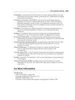
Figure 17-2 shows a simple network consisting of two Catalyst multilayer switches. Catalyst A sits
at the edge of the QoS domain, where this network joins another “public” network. Catalyst B, on
the other hand, sits inside the QoS domain and interfaces to some end user devices. One port con-
nects to a user PC and another port connects to a Cisco IP Phone. Another user PC connects to the
IP Phone’s data port.
Figure 17-2 Network Diagram for the QoS Example
NOTE The strict-priority queue is never a candidate for WRED-based drops. Instead, all packets
queued are guaranteed to be delivered. Only when the queue fills to capacity will new packets be
dropped, following standard tail-drop behavior.
Cisco
IP Phone
PC
Catalyst A Catalyst B
Public
Network
gig2/1 gig2/2 gig0/1
fa0/1
PC
fa0/2
IP
Untrusted
Trust
Boundary
Trust
Boundary
Untrusted
VLAN 200
VLAN 100
1-58720-077-5.book Page 417 Tuesday, August 19, 2003 3:16 PM
418 Chapter 17: DiffServ QoS Configuration
To configure QoS in this network, you must first define the QoS domain, where QoS information
will be known and trusted. The edge of this domain lies at the points where QoS information is no
longer trusted—at the trust boundaries. In Figure 17-2, a trust boundary exists where Catalyst A
connects to the public network. Another trust boundary exists where Catalyst B meets the end users.
The user PC should not be trusted because it might have applications that try to spoof or elevate the
QoS information to bogus values in an effort to get better service. The IP Phone itself can be trusted
because it is just another network device that can be configured and controlled. However, it lies at
another trust boundary where another user PC connects. (The details of QoS trust with an IP Phone
are discussed in Chapter 18 “IP Telephony.”)
Configuring QoS Trust
First, you should configure Catalyst A for its trust boundary on interface GigabitEthernet 2/1. Any
QoS information coming from the public network should be untrusted because you have no control
over the values being sent or who is sending them. You can use the following configuration com-
mands to accomplish this:
mls qos
interface gigabitethernet 2/1
no mls qos trust
Notice that the first command enabled QoS on the switch. Do not forget this important first step.
The interface is configured to consider all inbound QoS information as untrusted. As a result, any
inbound CoS (assuming this interface is a trunk) and DSCP values are set to 0, the default.
Notice also that this interface configuration command is not necessary because all switch ports are
configured as untrusted by default. This also means that all of Catalyst A’s ports that are inside the
QoS domain (the trusted side) will not trust QoS information that should be known and valid. Do
not forget to configure the trusted ports—every switch port that connects to another switch inside
your network. If you configure QoS consistently throughout your network, you can always trust the
QoS information as it moves about.
For this network, inbound DSCP information will be used as the trusted quantity. This is possible
because all the switches are multilayer switches and can understand and work with DSCP as an IP
or Layer 3 quantity. Catalyst A’s GigabitEthernet 2/2 interface is then configured as a trusted port
with the following configuration commands:
interface gigabitethernet 2/2
mls qos trust dscp
1-58720-077-5.book Page 418 Tuesday, August 19, 2003 3:16 PM
A QoS Configuration Example 419
Next, you must configure Catalyst B for its trust boundary. Interface GigabitEthernet 0/1 is on the
inside or trusted side of the QoS domain. Therefore, DSCP information can be trusted:
mls qos
interface gigabitethernet 0/1
mls qos trust dscp
Interface FastEthernet 0/2 connects to an end user’s PC and should not trust any QoS information.
The following configuration commands set the trust boundary and force any inbound CoS and
DSCP values to 0 (by default):
interface fastethernet 0/2
no mls qos trust
Interface FastEthernet 0/1 presents an interesting case. Here, a Cisco IP Phone is connected, trans-
porting Voice over IP (VoIP) traffic, as well as normal data from the attached PC. As Chapter 18
discusses, a Catalyst switch can detect an IP Phone via Cisco Discovery Protocol (CDP) and can
instruct the phone to extend a trust boundary to its auxiliary data port. The voice traffic from the
phone should be implicitly trusted because the phone is both a Cisco device and a small switch that
can be configured and controlled.
The PC connected to the phone, however, should normally be untrusted and have all inbound CoS
values set to 0. This is mentioned here to show how trust boundaries also exist at any connected IP
Phones. The following configuration commands for the phone trust boundary are fully explained in
Chapter 18:
interface fastethernet 0/1
switchport voice vlan 200
switchport priority extend cos 0
Configuring a QoS Class to Classify Traffic
In this example, suppose you need to make sure some types of traffic receive premium service within
your network. These types of traffic are classified at the QoS domain boundary, at Catalyst A. HTTP
traffic from a server at 10.1.1.1 is considered to contain important, time-critical market data for your
NOTE Remember that only inbound QoS information can be trusted. Outbound QoS information
is simply sent on to the next-hop switch or router where it will be evaluated against another trust
relationship there. Any DSCP information that Catalyst A accepts from the internal network will
also be forwarded out toward the public network on interface GigabitEthernet 2/1. Does the
network on the other side of the QoS boundary have to accept or trust the QoS information you
send? Only if it wants to. It is up to the network administrators on that end to decide what sort of
trust relationship to configure on their switches.
1-58720-077-5.book Page 419 Tuesday, August 19, 2003 3:16 PM
420 Chapter 17: DiffServ QoS Configuration
business. Any virtual private network (VPN) traffic using the IP Security (IPSec) protocol is also
considered to carry encrypted data to and from your business partners and remote sites.
First, you must configure a class map to match the HTTP and IPSec traffic. Use an extended access
list to identify TCP port 80 (HTTP), while using the NBAR feature to identify IPSec packets.
Configure the class map on Catalyst A with the following commands:
ip access-list extended MarketWWW
permit tcp host 10.1.1.1 any eq 80
class-map GoodTraffic match-any
match access-group name MarketWWW
match protocol ipsec
So far, the idea is to classify the time-critical, very important, or “good” traffic so that a QoS policy
can guarantee better service. Sometimes, classifying nuisance or “bad” traffic so that it can be given
a lower-level service migt also be necessary. In certain cases, you might choose to drop this type of
traffic altogether. Lowering the level of service prevents undesirable traffic from using the network
resources needed for more important traffic.
For this example, peer-to-peer file sharing traffic generated by the KaZaA version 2 applications is
considered to be unrelated to your business. It is tolerated for the benefit of the employees, but it
should receive only “best effort” service. Define a class map on Catalyst A to identify this type of
traffic with the following commands:
class-map BadTraffic match-any
match protocol kazaa2
Configuring a QoS Policy to Act on Classified Traffic
Now that class maps have been configured to classify or identify specific traffic, some action should
be performed to adjust the QoS parameters. This makes up the actual QoS policy, which is defined
as a policy map. First, traffic classified by the GoodTraffic class map is given a DSCP value of AF21
so that other switches know to provide good delivery service. Anything classifed by the BadTraffic
class map is given a DSCP value of 0, where only “best effort” or default delivery service is
requested.
After the policy map is configured, it is applied to an interface in the inbound direction. This
classifies and marks traffic as it is received, at the QoS boundary. The policy map is configured on
Catalyst A and applied with the following commands:
policy-map MyPolicy
class GoodTraffic
set ip dscp af21
class BadTraffic
set ip dscp 0
interface gigabitethernet 2/1
service-policy MyPolicy in
1-58720-077-5.book Page 420 Tuesday, August 19, 2003 3:16 PM
A QoS Configuration Example 421
Egress Queue Tuning
After packets have been classified and marked, you should also consider how the QoS information
will be used to queue and schedule packet delivery. In this example, DSCP values AF21 (18) and 0
have been used to mark traffic. In addition, Voice over IP (VoIP) packets associated with the IP
Phone on Catalyst B can be expected to have DSCP values AF31 (26) and EF (46). (Chapter 18
discusses this in more detail.) All other applications will have their packets marked to DSCP 0, as
a result of the trust boundaries configured throughout the network.
At a minimum, you should look at how the known DSCP values will be mapped to CoS values as
packets are sent to the egress queues. CoS is always used to decide how packets are queued and
scheduled for transmission. In the default state, before any further configuration is done, the DSCP-
to-CoS map looks like Table 17-5.
GoodTraffic packets (DSCP 18) are mapped to CoS 2, BadTraffic packets (DSCP 0) are CoS 0, and
VoIP packets (DSCP 26 and 46) become CoS 3 and 5, respectively.
After the CoS values are mapped, they are used to determine into which egress queue each packet
will be placed. By default, all switch ports have WRED enabled. For an egress port with a 1p2q2t
queueing strategy, the following scheduling occurs:
■ CoS 0 and 1: Standard queue 1, threshold 1
■ CoS 2 and 3: Standard queue 1, threshold 2
■ CoS 4: Standard queue 2, threshold 1
■ CoS 6 and 7: Standard queue 2, threshold 2
■ CoS 5: Always sent to the strict-priority queue
Assume this is an acceptable scheduling configuration, as CoS 3 will be serviced before CoS 2,
which will be serviced before CoS 0, and so on. CoS 5, used for the VoIP voice bearer packets, will
always be sent to the strict-priority queue. That queue is, by definition, always serviced before any
other queue. Indeed, that sounds reasonable for this example network. No other configuration
should be necessary, right?
Table 17-5 Default DSCP-to-CoS Value Mappings
DSCP 0-7
Default
8-15
AF10-AF13
16-23
AF20-AF23
24-31
AF30-AF33
32-39
AF40-AF43
40-47
EF
48-55
Internetwork
Control
56-63
Network
Control
CoS 0123456 7
1-58720-077-5.book Page 421 Tuesday, August 19, 2003 3:16 PM
422 Chapter 17: DiffServ QoS Configuration
Actually, the default condition for every switch port is to disable the strict-priority or expedite egress
queue. That is not what you need at all—the voice traffic having CoS 5 will be sent to a standard
queue to contend with other less time-critical traffic. If you expect to use the strict-priority queues,
do not forget to enable them. The example configuration concludes with the following configuration
commands on Catalyst A:
interface range gigabitethernet 2/1 – 2
priority-queue out
Catalyst B receives the following configuration commands:
interface gigabitethernet 0/1
priority-queue out
interface range fastethernet 0/1 – 2
priority-queue out
Verifying and Troubleshooting QoS
You can display information about many aspects of QoS on a Catalyst switch. Use the information
in Table 17-6 to determine which command is useful for a particular situation.
The show mls qos interface command shows the following information about an interface:
■ QoS trust (if any) configured on the interface
■ Default CoS value (if any) used to override inbound CoS
■ DSCP mutation map
■ QoS trust extension to a connected Cisco IP Phone
Table 17-6 Commands to Display Information About QoS on a Catalyst Switch
Task Command Syntax
Verify QoS trust settings on an
interface.
show mls qos interface type mod/num
Verify egress queueing on an
interface.
show mls qos interface type mod/num queueing
Verify QoS settings only on a
Catalyst 6500 interface.
show queueing interface type mod/num
View all QoS parameter mappings. show mls qos maps
1-58720-077-5.book Page 422 Tuesday, August 19, 2003 3:16 PM
Verifying and Troubleshooting QoS 423
Example 17-1 provides sample output from the show mls qos interface command.
The show mls qos interface queueing command shows the following information about an
interface:
■ Current state of the strict-priority (expedite) queue
■ WRR transmit queue weighting (bandwidth)
■ Egress queue ratios (qid-weights)
■ Egress queue scheduling (CoS-to-queue mapping)
Example 17-2 shows sample output from the show mls qos interface queueing command.
Example 17-1 show mls qos interface Command Output
Switch# ss
ss
hh
hh
oo
oo
ww
ww
mm
mm
ll
ll
ss
ss
oo
oo
ss
ss
ii
ii
nn
nn
tt
tt
ee
ee
rr
rr
ff
ff
aa
aa
cc
cc
ee
ee
gg
gg
ii
ii
gg
gg
aa
aa
bb
bb
ii
ii
tt
tt
ee
ee
tt
tt
hh
hh
ee
ee
rr
rr
nn
nn
ee
ee
tt
tt
00
00
//
//
11
11
GigabitEthernet0/1
trust state: trust cos
trust mode: trust cos
COS override: dis
default COS: 0
DSCP Mutation Map: Default DSCP Mutation Map
trust device: none
Example 17-2 show mls qos interface queueing Command Output
Switch# ss
ss
hh
hh
oo
oo
ww
ww
mm
mm
ll
ll
ss
ss
oo
oo
ss
ss
ii
ii
nn
nn
tt
tt
ee
ee
rr
rr
ff
ff
aa
aa
cc
cc
ee
ee
gg
gg
ii
ii
gg
gg
aa
aa
bb
bb
ii
ii
tt
tt
ee
ee
tt
tt
hh
hh
ee
ee
rr
rr
nn
nn
ee
ee
tt
tt
00
00
//
//
11
11
uu
uu
ee
ee
uu
uu
ee
ee
ii
ii
nn
nn
gg
gg
GigabitEthernet0/1
Egress expedite queue: dis
wrr bandwidth weights:
qid-weights
1 - 25
2 - 25
3 - 25
4 - 25
Dscp-threshold map:
d1 : d2 0 1 2 3 4 5 6 7 8 9
0 : 01 01 01 01 01 01 01 01 01 01
1 : 01 01 01 01 01 01 01 01 01 01
2 : 01 01 01 01 01 01 01 01 01 01
3 : 01 01 01 01 01 01 01 01 01 01
4 : 01 01 01 01 01 01 01 01 01 01
5 : 01 01 01 01 01 01 01 01 01 01
6 : 01 01 01 01
continues
1-58720-077-5.book Page 423 Tuesday, August 19, 2003 3:16 PM
424 Chapter 17: DiffServ QoS Configuration
Notice from the shaded text that the strict-priority (expedite) queue is disabled. This is the default
state for all interfaces, until the strict-priority queue is enabled with the priority-queue out interface
configuration command. Example 17-3 provides the same output after the strict-priority queue has
been enabled.
Cos-queue map:
cos-qid
0 - 1
1 - 1
2 - 2
3 - 2
4 - 3
5 - 3
6 - 4
7 - 4
Example 17-3 show mls qos interface queueing Command Output After Enabling the Strict-Priority Queue
Switch# cc
cc
oo
oo
nn
nn
ff
ff
ii
ii
gg
gg
tt
tt
ee
ee
rr
rr
mm
mm
Enter configuration commands, one per line. End with CNTL/Z.
Switch(config)# ii
ii
nn
nn
tt
tt
ee
ee
rr
rr
ff
ff
aa
aa
cc
cc
ee
ee
gg
gg
ii
ii
gg
gg
aa
aa
bb
bb
ii
ii
tt
tt
ee
ee
tt
tt
hh
hh
ee
ee
rr
rr
nn
nn
ee
ee
tt
tt
00
00
//
//
11
11
Switch(config-if)# pp
pp
rr
rr
ii
ii
oo
oo
rr
rr
ii
ii
tt
tt
yy
yy
uu
uu
ee
ee
uu
uu
ee
ee
oo
oo
uu
uu
tt
tt
Switch(config-if)#^^
^^
ZZ
ZZ
Switch#
Switch# ss
ss
hh
hh
oo
oo
ww
ww
mm
mm
ll
ll
ss
ss
oo
oo
ss
ss
ii
ii
nn
nn
tt
tt
ee
ee
rr
rr
ff
ff
aa
aa
cc
cc
ee
ee
gg
gg
ii
ii
gg
gg
aa
aa
bb
bb
ii
ii
tt
tt
ee
ee
tt
tt
hh
hh
ee
ee
rr
rr
nn
nn
ee
ee
tt
tt
00
00
//
//
11
11
uu
uu
ee
ee
uu
uu
ee
ee
ii
ii
nn
nn
gg
gg
GigabitEthernet0/1
Egress expedite queue: ena
wrr bandwidth weights:
qid-weights
1 - 25
2 - 25
3 - 25
4 - 25 when expedite queue is disabled
Dscp-threshold map:
d1 : d2 0 1 2 3 4 5 6 7 8 9
0 : 01 01 01 01 01 01 01 01 01 01
[other output deleted]
Example 17-2 show mls qos interface queueing Command Output (Continued)
1-58720-077-5.book Page 424 Tuesday, August 19, 2003 3:16 PM
Foundation Summary 425
Foundation Summary
The Foundation Summary is a collection of information that provides a convenient review of many
key concepts in this chapter. If you are already comfortable with the topics in this chapter, this
summary can help you recall a few details. If you just read this chapter, this review should help
solidify some key facts. If you are doing your final preparation before the exam, this summarized
information is a convenient way to review the day before the exam.
You can configure a switch to trust the following inbound QoS parameters:
■ CoS (from a trunk)
■ DSCP (from IP headers)
■ IP Precedence (from IP headers)
Remember the basic structure of modular QoS configuration:
1. Define a QoS class map to classify specific traffic for a policy; define as many class maps as
necessary.
2. Define a QoS policy that uses class maps to identify traffic; the policy also contains actions with
each class map that will be taken on classified traffic.
3. Apply the QoS policy to an interface. One policy can be applied to an inbound traffic flow and
one to an outbound traffic flow.
Table 17-7 QoS Trust Configuration Commands
Task Command Syntax
Enable QoS on a switch. mls qos
Choose inbound QoS info to trust on an interface. mls qos trust {cos | dscp | ip-precedence}
Or none at all. no mls qos trust
1-58720-077-5.book Page 425 Tuesday, August 19, 2003 3:16 PM
426 Chapter 17: DiffServ QoS Configuration
Table 17-8 QoS Class Configuration Commands
Task Command Syntax
Define a class map. class-map class-name [match-all | match-any]
Classify with an access list.
1
match access-group name access-list
Classify by IP Precedence. match ip precedence ipprec1 [ ipprecN]
Classify by DSCP. match ip dscp dscp1 [ dscpN]
Classify with NBAR. match protocol protocol-name
1
An access list (either numbered or named) must be configured separately, in global configuration mode.
Table 17-9
QoS Policy Configuration Commands
Task Command Syntax
Define a policy map. policy-map policy-name
Classify with a class map. class class-name
Mark the DSCP value. set ip dscp dscp-value
Mark the IP Precedence value. set ip precedence ip-precedence-value
Trust inbound QoS information. trust {cos | dscp | ip-precedence}
Police the classified flow. police
Apply the policy map to an interface. service-policy [input | output] policy-name
1-58720-077-5.book Page 426 Tuesday, August 19, 2003 3:16 PM
Foundation Summary 427
Table 17-10 QoS Egress Queue Configuration Commands
Task Command Syntax
Set the WRR queue weighting. wrr-queue bandwidth weight1 weight2 [weight3]
Map packets into egress queues. wrr-queue cos-map queue-id threshold-id cos-list
Use tail-drop queue management. no wrr-queue random-detect queue-id
Use WRED. wrr-queue random-detect queue-id
Set the WRED queue thresholds. wrr-queue random-detect {max-threshold | min-threshold}
queue-id threshold-percent-1 threshold-percent-N
Table 17-11 Commands for Verifying QoS Operation
Task Command Syntax
Verify QoS trust settings on an
interface.
show mls qos interface type mod/num
Verify egress queueing on an
interface.
show mls qos interface type mod/num queueing
Verify QoS settings only on a
Catalyst 6500 interface.
show queueing interface type mod/num
View all QoS parameter mappings. show mls qos maps
1-58720-077-5.book Page 427 Tuesday, August 19, 2003 3:16 PM
428 Chapter 17: DiffServ QoS Configuration
Q&A
The questions and scenarios in this book are more difficult than what you should experience on the
actual exam. The questions do not attempt to cover more breadth or depth than the exam; however,
they are designed to make sure that you know the answers. Rather than allowing you to derive the
answers from clues hidden inside the questions themselves, the questions challenge your under-
standing and recall of the subject. Hopefully, these questions will help limit the number of exam
questions on which you narrow your choices to two options and then guess.
You can find the answers to these questions in Appendix A.
1. What two ways can QoS trust be configured on a switch?
2. If all QoS trust decisions will be applied as part of a QoS policy, what command should you use
on an interface?
3. When a class map is configured, what types of commands must also be used?
4. Name two methods that you can use to identify or classify traffic.
5. What command can classify traffic with an extended IP access list?
6. What command can classify traffic with NBAR?
7. What does a policy map contain?
8. When a policy map is applied to an interface, does it control both inbound and outbound traffic?
9. What is the first command keyword used to configure WRED congestion avoidance?
10. What QoS information is used to map packets into the egress queues of a switch port?
11. What command can set the WRED thresholds of the strict-priority queue (1p2q2t) to 25 percent
and 75 percent?
12. What command can display the QoS and queue information about a switch port?
1-58720-077-5.book Page 428 Tuesday, August 19, 2003 3:16 PM
1-58720-077-5.book Page 429 Tuesday, August 19, 2003 3:16 PM
This chapter covers the
following topics that you
need to master for the CCNP
BCMSN exam:
■ Inline Power—This section discusses how a
Catalyst switch can provide power to operate
a Cisco IP Phone.
■ Voice VLANs—This section explains how
voice traffic can be carried over the links
between an IP Phone and a Catalyst switch.
■ Voice QoS—This section provides an
overview of the mechanisms that provide
premium quality of service (QoS) for voice
traffic.
■ Verifying IP Telephony—This section pro-
vides a brief summary of the commands that
can verify the configuration and operation of
IP Telephony features.
1-58720-077-5.book Page 430 Tuesday, August 19, 2003 3:16 PM
C H A P T E R
18
IP Telephony
Switched campus networks can carry packets that are related to telephone calls, as well as
regular data. Voice over IP (VoIP), otherwise known as IP Telephony (IPT), uses IP Phones that
are connected to switched Ethernet ports.
To properly and effectively carry the traffic for a successful phone call, a combination of many
switching features must be used. For example, the Catalyst switches can provide power to IP
Phones, form trunk links with IP Phones, and provide the proper level of QoS for voice packet
delivery. This chapter covers all these topics as related to the Cisco IP Phone.
“Do I Know This Already?” Quiz
The purpose of the “Do I Know This Already?” quiz is to help you decide what parts of this
chapter to use. If you already intend to read the entire chapter, you do not necessarily need to
answer these questions now.
The quiz, derived from the major sections in the “Foundation Topics” portion of the chapter,
helps you determine how to spend your limited study time.
Table 18-1 outlines the major topics discussed in this chapter and the “Do I Know This
Already?” quiz questions that correspond to those topics.
Table 18-1 “Do I Know This Already?” Foundation Topics Section-to-Question Mapping
Foundation Topics Section Questions Covered in This Section
Inline Power 1–2
Voice VLANs 3–7
Voice QoS 8–10
Verifying IP Telephony 11–12
1-58720-077-5.book Page 431 Tuesday, August 19, 2003 3:16 PM
432 Chapter 18: IP Telephony
1.
For a Catalyst switch to offer inline power to a device, what must occur?
a. Nothing; inline power is always enabled on a port.
b. The switch must detect that the device needs inline power.
c. The device must send a CDP message asking for power.
d. The switch is configured to turn on inline power to the port.
2. Which one of these commands can enable inline power to a switch interface?
a. inline power enable
b. inline power on
c. power inline on
d. power inline auto
3. What does a Cisco IP Phone contain to allow it to pass both voice and data packets?
a. An internal Ethernet hub
b. An internal two-port switch
c. An internal three-port switch
d. An internal four-port switch
4. How can voice traffic be kept separate from any other data traffic through an IP Phone?
a. Voice and data travel over separate links.
b. A special-case 802.1Q trunk is used to the switch.
c. Voice and data can’t be separated; they must intermingle on the link.
d. Voice and data packets are both encapsulated over an ISL trunk.
5. What command configures an IP Phone to use VLAN 9 for voice traffic?
a. switchport voice vlan 9
b. switchport voice-vlan 9
c. switchport voice 9
d. switchport voip 9
CAUTION The goal of self-assessment is to gauge your mastery of the topics in this chapter. If
you do not know the answer to a question or are only partially sure of the answer, you should mark
this question wrong. Giving yourself credit for an answer you correctly guess skews your self-
assessment results and might give you a false sense of security.
1-58720-077-5.book Page 432 Tuesday, August 19, 2003 3:16 PM