Visualizing Project Management Models and frameworks for mastering complex systems 3rd phần 9 ppt
Bạn đang xem bản rút gọn của tài liệu. Xem và tải ngay bản đầy đủ của tài liệu tại đây (1.08 MB, 48 trang )
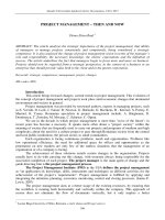
Figure 19.18 Incremental development—incremental delivery, with evolutionary iterations on increment 3.
Incremental/Linear and Evolutionary Development
Single or Multiple Deliveries
Increment 1 PDR
Code, Fab, Assemble
Increment 3
PDR
Increment 2
PDR
System PDR
Increment 1 PDR
Code, Fab, Assemble
Increment 3
PDR
Increment 2
PDR
System PDR
Code, Fab, Assemble
Increment 3
PDR
Increment 2
PDR
System PDR
Incre
1+2
Verif.
& Possible
Delivery
Incre 1
Verif.
& Possible
Delivery
Incre 1
TRR
Incre
1+2
TRR
Increment 3
Evolutionary Development
Version 1
Incre
1+2
Verif.
& Possible
Delivery
Incre 1
Verif.
& Possible
Delivery
Incre 1
TRR
Incre
1+2
TRR
Increment 3
Evolutionary Development
Version 1
Incre
1+2
Verif.
& Possible
Delivery
Incre 1
Verif.
& Possible
Delivery
Incre 1
TRR
Incre
1+2
TRR
Increment 3
Evolutionary Development
Version 1
Incre 1
Verif.
& Possible
Delivery
Incre 1
TRR
Incre
1+2
TRR
Incre 1
Verif.
& Possible
Delivery
Incre 1
TRR
Incre
1+2
TRR
Incre 1
Verif.
& Possible
Delivery
Incre 1
TRR
Incre
1+2
TRR
Increment 3
Evolutionary Development
Version 1
System
Accept
& Deliver
Integrate
1+2+3
System
TRR
Version 2
Version 3
System
Accept
& Deliver
Integrate
1+2+3
System
TRR
System
Accept
& Deliver
Integrate
1+2+3
System
TRR
Version 2
Version 3
Figure 19.17 Incremental development—single or multiple delivery.
Incremental/Linear Development
Single or Multiple Increment Deliveries
Examples:
Multiple Delivery
• San Jose Light Rail
– Phase 1 1990
10 mi of track
– Phase 2 1993
18 mi of track
– Phase 3 20??
X mi of track to
adjacent cities
Single Delivery
• St. Gotthard Alps Tunnel
- SedrumStart – 4/1996
- Amsteg Start – 71999
- Faido Start – 7/1999
- Bodio Start – 9/1999
- Erstfeld Start – 1/2002
- Commission - 2011
Code, Fab, Assemble Units
Increment 3
PDR
Increment 2
PDR
Code, Fab, Assemble Units
Increment 3
PDR
Increment 2
PDR
Increment 1 PDR
System PDR
Increment 1 PDR
System PDR
Incre
1+2
Verif.
& Possible
Delivery
System
Accept
& Deliver
Integrate
1+2+3
System
TRR
Incre
1+2
Verif.
& Possible
Delivery
System
Accept
& Deliver
Integrate
1+2+3
System
TRR
Incre
1+2
Verif.
& Possible
Delivery
System
Accept
& Deliver
Integrate
1+2+3
System
TRR
System
Accept
& Deliver
Integrate
1+2+3
System
TRR
Incre 1
Verif.
& Possible
Delivery
Incre 1
TRR
Incre
1+2
TRR
Incre 1
Verif.
& Possible
Delivery
Incre 1
TRR
Incre
1+2
TRR
Incre 1
Verif.
& Possible
Delivery
Incre 1
TRR
Incre
1+2
TRR
Incre 1
Verif.
& Possible
Delivery
Incre 1
TRR
Incre
1+2
TRR
Incre 1
Verif.
& Possible
Delivery
Incre 1
TRR
Incre
1+2
TRR
cott_c19.qxd 7/5/05 3:08 PM Page 358
PRINCIPLES AND TACTICS FOR MASTERING COMPLEXITY 359
activities and unplanned reactive activities such as late suppliers
and quality problems.
As discussed in Chapter 12, the management of the critical path
is usually focused on the task schedules and their dependencies, as
represented by the structure of the project network. But prema-
turely focusing on precise calculation of the critical path may be
missing the forest for the trees. The purpose of this section is to
highlight the interdependency between the technical development
tactics and the critical path throughout the project cycle.
Deployment strategies have a strong influence on the critical
path, especially the early part. A strategy might be to capture mar-
ket share by deploying a system solution quickly even though it
might not initially achieve its full performance goals. Another strat-
egy might be to field a system that is easily upgradeable after intro-
duction to provide after-market sales. The resulting development
tactics, selected for system entities, determine the connections
among tasks and the relationships that form the project network.
When the predicted task schedules are applied, their summation de-
termines the length of the critical path.
In considering the development tactics, we sometimes misjudge
theimportance of integration, verification, and validation (IV&V)
tactics. Projects that require the ultimate in reliability will usually
adoptabottom up step-by-step IV&V sequence of proving perfor-
manceatevery entity combination. High-quantity production sys-
tems may skip verification once the production processes have been
proven to reliab
ly produce perfectproducts. Yet other projects may
elect a “threaded” or “big bang” verification approach. It is not un-
common for different project entities to embrace different task-
dependent verification and validation tactics. The tasks associated
with these tactical decision activities must also be incorporated into
thecritical path to accurately represent the planned approach. These
system integration and verification activities will almost always be on
thecritical path.The next chapter addresses IV&V in detail.
ARTIFACTS AND THEIR ROLES
Project management artifacts are the results of communication
among the project participants. Documentation is the most common
artifact, but models, products, material samples, and even white-
board sketches are valid artifacts. Artifacts are representations of
facts and can be binding when used as such. Some projects managed
in a bureaucratic environment develop too many artifacts without
regard to their purpose and ultimate use. The three fundamental
roles that artifacts fulfill are (Figure 19.19):
cott_c19.qxd 7/5/05 3:08 PM Page 359
360 IMPLEMENTING THE FIVE ESSENTIALS
1.
Manage the elaboration of the development baseline. Since all
team members should be working to the most current elaboration,
it needs to be communicated among the team. The artifacts can
range from oral communication to volumes of documentation. In
a small skunk works team environment, whiteboard sketches are
highly effective as long as they are permanent throughout the
time they are needed (simply writing SAVE across the board may
not be strong enough). These artifacts include system require-
ments, concept definition, architecture, design-to specifications,
build-to documentation, and as-built documentation.
2. Communicate to the verification and operations personnel what
they need to know to carry out their responsibilities. These arti-
facts communicate the expected behavior over the anticipated
operational scenarios. These artifacts include user’s manuals,
operator’s manuals, practice scenarios, verification plans, veri-
fication procedures, validation plans, and validation procedures.
3.
Provide for repair and replication. These must represent the as-
operated configuration, which should include all modifications
made to the as-built baseline. These artifacts include the as-built
artifacts together with all modifications incorporated, process
specifications, parts lists, material specifications, repair manu-
als, and source code.
Figure 19.19 The three roles for artifacts.
Verification
& Operations
Artifacts
provide the
ability to verify
and operate as
expected.
Artifacts
provide the
ability to verify
and operate as
expected.
Managing the Solution Development
Managing the Solution Development
Baseline
Elaboration
Artifacts
control the
solution
maturation.
Artifacts
control the
solution
maturation.
Replication
& Repair
Artifacts
provide the
ability to repair
and replicate
as designed.
Artifacts
provide the
ability to repair
and replicate
as designed.
cott_c19.qxd 7/5/05 3:08 PM Page 360
361
20
INTEGRATION,
VERIFICATION,
AND VALIDATION
C
hapter 7 addressed integration, verification, and validation
(IV&V) as represented by the Vee Model and in relationship to
the systems engineering role. In Chapter 9, the planning for IV&V
was emphasized in the Decomposition Analysis and Resolution pro-
cess, followed by a broad implementation overview in the Verifica-
tion Analysis and Resolution process. This chapter addresses the
implementation of IV&V in more depth.
Successful completion of system-level integration, verification,
and validation ends the implementation period and initiates the op-
erations period, which starts with the production phase if more than
one article is to be delivered. However, if this is the first point in
the project cycle that IV&V issues have been considered, the team’s
only allies will be hope and luck, four-letter words that should not be
part of any project’s terminology manual.
We have emphasized that planning for integration and verifica-
tion starts with the identification of solution concepts (at the system,
subsystem, and lowest entity levels). In fact, integration and verifica-
tion issues may be the most significant discriminators when selecting
from alternate concepts. Equally important, the project team should
not wait until the end of the implementation period to determine if
the customer or user(s) likes the product. In-process validation should
progress to final validation when the user stresses the system to en-
sure satisfaction with all intended uses. A system is often composed of
hardware, software, and firmware. It sometimes becomes “shelfware”
Integration: The successive
combining and testing of sys-
tem hardware assemblies,
software components, and
operator tasks to progressively
prove the performance and
capability of all entities of the
system.
Verification: Proof of compli-
ance with specifications.
Was the solution built right?
Validation: Proof that the
user(s) is satisfied.
Was the right solution built?
When an error reaches the
field, there have been two
errors. Verification erred by
failing to detect the fielded
error.
cott_c20.qxd 6/30/05 3:55 PM Page 361
362 IMPLEMENTING THE FIVE ESSENTIALS
Verification complexity
increases exponentially with
system complexity.
In cases of highest risk, Inde-
pendent Verification and Vali-
dation is performed by a
team that is totally indepen-
dent from the developing
organization.
when the project team did not take every step possible to ensure user
acceptance. Yet, this is a frequent result, occurring much too often.
Most recently, the failure of a three-year software development pro-
gram costing hundreds of millions of dollars has been attributed to
the unwillingness of FBI agents to use the system (a validation fail-
ure). These surprise results can be averted by in-process validation,
starting with the identification of user needs and continuing with user
confirmation of each elaboration of the solution baseline.
IV&V has a second meaning: independent verification and vali-
dation used in high-risk projects where failure would have profound
impact. See the Glossary for a complete definition. Examples are the
development of the control system for a nuclear power plant and the
on-board flight-control software on the space shuttle. The IV&V
process on the shuttle project resulted in software that had an im-
pressively low error rate (errors per thousand lines of code) that was
one-tenth of the best industry practice. Proper development
processes do work.
In the project environment, IV&V is often treated as if it were
a single event. This chapter details each of these three distinct
processes. Integration is discussed first. Then the discussion of ver-
ification covers design verification, design margin verification and
qualification, reliability verification, software quality verification,
and system certification. Validation covers issues in interacting
with users, both external and internal to the project team. In clos-
ing, anomaly management addresses the unexpected.
INTEGRATION
The integration approach will drive the key details of the product
breakdown structure (PBS), the work breakdown structure (WBS),
the network logic, and the critical path. Interface specifications de-
fine the physical and logical requirements that must be met by enti-
ties on both sides of the interface. These specifications must cover
both internal interfaces as well as those external to the system. A
long-standing rule is to keep the interfaces as simple and fool proof
as possible.
Integration takes place at every level of the system architecture.
The PBS (see examples in margin opposite Figure 20.1) identifies
where these interfaces occur. In Figure 20.1, the N
2
diagram illus-
trates relationships between system entities and relates the entities
to the PBS. The entities are listed on the diagonal of the matrix, with
outputs shown in the rows and inputs in the columns. For instance,
Integration: The successive
combining and testing of sys-
tem hardware assemblies,
software components, and
operator tasks to progressively
prove the performance and
capability of all entities of the
system.
cott_c20.qxd 6/30/05 3:55 PM Page 362
INTEGRATION, VERIFICATION, AND VALIDATION 363
Entity B has input from Entities A and C, as well as input from out-
side the system. In Figure 20.1, Entity B provides an output external
to the system. Interfaces needing definition are identified by the ar-
rows inside the cells. The BMW automobile manufacturer has suc-
cessfully used a similar matrix with over 270 rows and columns to
identify critical interface definitions.
Integration and verification planning, which must have project
management focus from the outset, begins in the concept develop-
ment phase. The planning must answer the following questions:
• What integration tasks are needed?
•Who will perform each task?
•Where will the task be performed?
• What facilities and resources are needed?
•When will the integration take place?
Integration and verification plans should be available at the
design-t
o decision gate.
There are four categories of integration:
1. Mechanical:
•Demonstrates mechanical compatibility of components.
•Demonstrates compliance with mechanical interface speci-
fications.
2. Electrical:
•Demonstrates electrical/electronic compatibility of com-
ponents.
•Demonstrates compliance with electrical interface require-
ments.
Figure 20.1 Interfaces illustrated by the N
2
and PBS diagrams.
ABCD
A B C D
ABCD
A B C D
O
A
B
I
O
A
D
I
O
C
D
I
O
C
B
I
O
C
A
I
O
D
A
I
O
D
C
I
A
Output
Input
Output
Input
B
C
D
Output
O
A
B
I
O
A
O
A
B
I
B
I
O
A
D
I
O
A
O
A
D
I
D
I
O
C
D
I
O
C
O
C
D
I
D
I
O
C
B
I
O
C
O
C
B
I
B
I
O
C
A
I
O
C
O
C
A
I
A
I
O
D
A
I
O
D
O
D
A
I
A
I
O
D
C
I
O
D
O
D
C
I
C
I
AAA
Output
Input
Output
Input
Output
Input
Output
Input
BBB
CCC
DDD
Output
ABCD
A
AB CD
CD
A
DCAB
ABCD
B
B
Integration Planning
cott_c20.qxd 6/30/05 3:55 PM Page 363
364 IMPLEMENTING THE FIVE ESSENTIALS
3. Logical:
•Demonstrateslogical (protocol) compatibility of components.
•Demonstrates the ability to load and configure software.
4. Functional:
•Demonstrates the ability to load, configure, and execute solu-
tion components.
•Demonstrates functional capability of all elements of the so-
lution working together.
Integration can be approached all at once (the “big bang”) or in-
crementally. Except for very simple systems, the big-bang approach
is generally considered too risky. Table 20.1 shows four incremental
approaches. Three of these (top-down, bottom-up, and thread) are
illustrated in Figure 20.2. Each approach is valid, and the choice de-
pends on the project circumstances.
Interface management to facilitate integration and verification
should be responsive to the following:
•ThePBS portion of the WBS should provide the road map for
integration.
•Integration will exist at every level in the PBS except at the top
level.
•Integration and verification activities should be represented by
tasks within the WBS.
Table 20.1 Incremental Integration Approaches
Technique Features
Top-down Control logic testing first.
Modules integrated one at a time.
Emphasis on interface verification.
Bottom-up Early verification to prove feasibility and practicality.
Modules integrated in clusters.
Emphasis on module functionality and performance.
Thread Top-down or bottom-up integration of a software
function or capability.
Mixed Working from both ends toward the middle.
Choice of modules designated top-down versus bottom-
up is critical.
cott_c20.qxd 6/30/05 3:55 PM Page 364
INTEGRATION, VERIFICATION, AND VALIDATION 365
•The WBS is not complete without the integration and verifica-
tion tasks and the tasks to produce the products (e.g., fixtures,
models, drivers, databases) required to facilitate integration.
•Interfaces should be designed to be as simple and foolproof
as possible.
•Interfaces should have mechanisms to prevent inadvertent in-
correct coupling (for instance, uniquely shaped connectors such
as the USB and S-Video connectors on laptop computers).
•Interfaces should be verified by low-risk (benign) techniques
before mating.
•“OK to install” discipline should be invoked before all matings.
•Peer review should provide consent-to authorization to proceed.
•Haste without extra care should be avoided. (If you cannot pro-
vide adequate time or extra care, go as fast as you can so there
will be time to do it over . . . and over. . . .)
Integration Issues
• Clear definition, documentation, and management of the inter-
faces are key to successful integration.
Figure 20.2 Alternative incremental integration approach tactics.
Stub
B
Stub
GE
D
C
F
Drivers
Top-Down
Not yet integrated
Already integrated
Implements
Requirement A
A
B L
M
Stub
KD
IH
Driver (simulate)
Requirement A
G
Threaded
Driver
B L
K
I
D
HG
Bottom-Up
Driver/Stub
J
Stub
Driver/Stub
J
Stub
Stub
Legend
:
Drivers and Stubs
Special test items to
simulate the start (
Driver
)
or end (
Stub
) of a chain
cott_c20.qxd 6/30/05 3:55 PM Page 365
366 IMPLEMENTING THE FIVE ESSENTIALS
•Coordination of schedules with owners of external systems is es-
sential for integration into the final environment.
•Resources must be planned. This includes the development of
stub and driver simulators.
•First-time mating needs to be planned and carefully performed,
step-by-step.
•All integration anomalies must be resolved.
•
Sometimes it will be necessary tofixthe“otherperson’s”
problem.
Risk: The Driver of Integration/Verification Thoroughness
It is important to know the project risk philosophy (risk tolerance) as
compared to the opportunity being pursued. This reward-to-risk
ratio will drive decisions regarding the rigor and thoroughness of in-
tegration and the many facets of verification and validation. There is
no standard vocabulary for expressing the risk philosophy, but it is
often expressed as “quick and dirty,” “no single point failure modes,”
“must work,” “reliability is 0.9997,” or some other expression or a
combination of these. One client reports that their risk tolerant
client specifies a 60 percent probability of success. This precise ex-
pression is excellent but unusual. The risk philosophy will determine
whetherall or onlyaportion of thefollowing will be implemented.
VERIFICATION
If adefectisdelivered within a system, it is a failure of verification
for not detecting the defect. Many very expensive systems have failed
after deployment due to built-in errors. In every case, there were two
failures. First the failure to build the system correctly and second the
failure of the verification process to detect the defect. The most fa-
mousisthe Hubble telescope delivered into orbit with a faulty mir-
ror. There are many more failures just as dramatic that did not make
newspaper headlines. They were even more serious and costly, but
unlike the Hubble, they could not be corrected after deployment.
Unfortunately, in the eagerness to recover lost schedule, verifi-
cation is often reduced or oversimplified, which increases the
chances of missing a built-in problem.
There are four verification methods: test, demonstration, analy-
sis, and inspection. While some consider simulation to be a fifth
method, most practitioners consider simulation to be one of—or a
combination of—test, analysis, or demonstration.
Verification management:
Proof of compliance with
specifications.
Was the solution built right?
cott_c20.qxd 6/30/05 3:55 PM Page 366
INTEGRATION, VERIFICATION, AND VALIDATION 367
Ver ification Methods Defined
Test (T): Direct measurement of performance relative to func-
tional, electrical, mechanical, and environmental requirements.
Demonstration (D): Ver if ication by witnessing an actual opera-
tion in the expected or simulated environment, without need for
measurement data or post demonstration analysis.
Analysis (A): An assessment of performance using logical, math-
ematical, or graphical techniques, or for extrapolation of model
tests to full scale.
Inspection (I): Ver if ic ation of compliance to requirements that
are easily observed such as construction features, workmanship,
dimensions, configuration, and physical characteristics such as
color, shape, software language used, and so on.
Test is a primary method for verification. But as noted previ-
ously, verification can be accomplished by methods other than test.
And tests are run for purposes other than verification (Figure 20.3).
Consequently, extra care must be taken when test results will be
used formally for official verification.
Engineering models are often built to provide design feasibil-
ity information. The test article is usually discarded after test com-
pletion. However, if the test article is close to the final
configuration, with care in documenting the test details (setup,
equipment calibration, test article configuration, etc.), it is possi-
ble that the data can be used for design verification or qualifica-
tion. The same is true of a software development prototype. If care
Figure 20.3 Test and verification.
cott_c20.qxd 6/30/05 3:55 PM Page 367
368 IMPLEMENTING THE FIVE ESSENTIALS
is used in documenting the test stubs, drivers, conditions, and
setup, it might be possible to use the development test data for ver-
ification purposes.
The management of verification should be responsive to lessons
learned from past experience. Eight are offered for consideration:
1.
A requirements traceability and verification matrix (RTVM)
should map the top-down decomposition of requirements and
should also identify the integration level and method for the
verification. For instance, while it is desirable to verify all re-
quirements in a final all-up systems test, there may be require-
ments that cannot be verified at that level. Often there are
stowed items at the system level that cannot and will not be de-
ployed until the system is deployed. In these instances, verifi-
cation of these entities must be achieved at a lower level of
integration. The RTVM should ensure that all required verifi-
cation is planned for, including the equipment and faculties
required to support verification at each level of integra-
tion. An example of a simple RTVM for a bicycle is shown in
Figure 20.4
.
2. The measurement units called out in verification procedures
should match the units of the test equipment to be used. For ex-
ample, considerable damage was done when thermal chambers
were inadvertently set to 160 degrees centigrade although the
verification procedure called for 160 degrees Fahrenheit. In an-
other instance, a perfectly good spacecraft was destroyed when
the range safety officer, using the wrong flight path dimensions,
destroyed it during ascent thinking it was off course. Unfortu-
nately, there are too many examples of perfect systems being
damaged by error.
3.
Redline limits are “do not exceed” conditions, just as the red
line onacar’s tachometer is designed to protect the car’s en-
gine. Test procedures should contain two types of redline lim-
its. The first should be set at the predicted values so that if
they are approached or exceeded the test can be halted and an
investigation initiated to determine why the predictions and
actual results don’t correlate. The second set of redline limits
should be set at the safe limit of capability to prevent failure of
the system or injury to personnel. If these limits are ap-
proached the test should be terminated and an investigation
should determine the proper course of action. One of the
world’s largest wind tunnels was destroyed when the test pro-
cedures that were required to contain redline limits did not.
cott_c20.qxd 6/30/05 3:55 PM Page 368
INTEGRATION, VERIFICATION, AND VALIDATION 369
During system verification, the testers unknowingly violated
engineering loadpredictionsby25times,taking the system to
structural failure and total collapse. The failure caused a four-
year facility shutdown for reconstruction.
4. A test readiness review should precede all testing to ensure
readiness of personnel and equipment. This review should in-
clude all test participants and should dry run the baselined ver-
ification procedure, including all required updates. Equipment
used to measure verification performance should be confirmed
to be ‘‘in calibration,” projected through the full test duration
including the data analysis period.
5. Formal testing should be witnessed by a “buyer” representative
to officially certify and accept the results of the verification.
Informal testing should precede formal testing to discover and
resolve all anomalies. Formal testing should be a predetermined
success based on successful informal testing.
Figure 20.4 Requirements traceability and verification matrix (RVTM) example.
Level
Rev
ID Name
Make
or
Buy
Requirement Predecessor Verification
000.0 Bicycle System M 0.0.1 "Light Wt" - <105% of Competitor "User Need" Doc ¶ 1 0.0.1 Assess Competition Auditor Date
000.0 Bicycle System M 0.0.2 "Fast" - Faster than any other bi
k
"User Need" Doc ¶ 2 0.0.2 Win Tour de France
101.1 Bicycle M 1.1.1 8.0 KG max weight 0.0.1, Marketing 1.1.1 Test (Weigh bike)
101.1 Bicycle M 1.1.2 85 cm high at seat Racing rules ¶ 3.1 1.1.2 Test (Measure bike)
101.1 Bicycle M 1.1.3 66 cm wheel dia Racing rules ¶ 4.2
Verif at ass'y level
101.1 Bicycle M 1.1.4 Carry one 90 KG rider Racing rules ¶ 2.2 1.1.4 Demonstration
101.1 Bicycle M 1.1.5 Use advanced materials Corporate strategy ¶ 6a
Verif at ass'y level
101.1 Bicycle M 1.1.6 Survive FIVE seasons Corporate strategy ¶ 6b 1.1.6 Accelerated life test
101.1 Bicycle M 1.1.7 Go VERY fast (>130 kpm) 0.0.2 1.1.7 Test against benchmark
101.1 Bicycle M 1.1.8 Paint frame Red, shade 123 Marketing 1.1.8 Inspection
101.2 Packaging B 1.2.1 Packaged for Shipment 0.0.4, Marketing
111.2 Packaging B 1.2.1 Photo of "Hi Tech" Wheel on Box 0.0.4, Marketing
101.2 Packaging B 1.2.2 Survive 2 m drop Industry std
111.3 Documentation M 1.3.1 Assembly Instructions 0.0.4
111.3 Documentation M 1.3.2 Owner's Manual 0.0.4
202.1 Frame Assembly B 2.1.1 Welded Titanium Tubing 1.1.5, 1.1.6
202.1 Frame Assembly B 2.1.2 Maximum weight 2.5 KG 1.1.1, allocation
202.1 Frame Assembly B 2.1.3 Demo 100 K cycle fatigue life 1.1.6
202.1 Frame Assembly B 2.1.4 Support 2 x 90 KG 1.1.4, 1.1.6
••
••
••
Level
Rev
ID Name
Make
or
Buy
Requirement Predecessor Verification
000.0 Bicycle System M 0.0.1 "Light Wt"
-
<105% of Competitor "User Need" Doc ¶ 1 0.0.1 Assess Competition Auditor Date
000.0 Bicycle System M 0.0.2
"Fast"
-
Faster
than
any
other
bike
"User Need" Doc ¶ 2 0.0.2 Win Tour de France
101.1 Bicycle M 1.1.1 8.0 KG max weight 0.0.1, Marketing 1.1.1 Test (Weigh bike)
101.1 Bicycle M 1.1.2 85 cm high at seat Racing rules ¶ 3.1 1.1.2 Test (Measure bike)
101.1 Bicycle M 1.1.3 66 cm wheel dia Racing rules ¶ 4.2
Verif at ass'y level
101.1 Bicycle M 1.1.4
Carry one 90 KG rider
Racing rules ¶ 2.2 1.1.4 Demonstration
101.1 Bicycle M 1.1.5
Use advanced materials
Corporate strategy ¶ 6a
Verif at ass'y level
101.1 Bicycle M 1.1.6
Survive FIVE seasons
Corporate strategy ¶ 6b 1.1.6 Accelerated life test
101.1 Bicycle M 1.1.7
Go VERY fast (>130 kpm)
0.0.2 1.1.7 Test against benchmark
101.1 Bicycle M 1.1.8 Paint frame Red, shade 123 Marketing 1.1.8 Inspection
101.2 Packaging B 1.2.1 Packaged for Shipment 0.0.4, Marketing
111.2 Packaging B 1.2.1 Photo
of
"Hi
Tech"
Wheel
on
Box 0.0.4, Marketing
101.2 Packaging B
1.2.2
Survive 2 m drop
Industry std
111.3 Documentation M 1.3.1 Assembly Instructions 0.0.4
111.3 Documentation M 1.3.2 Owner's Manual 0.0.4
202.1 Frame
Assembly B 2.1.1 Welded Titanium Tubing 1.1.5, 1.1.6
202.1 Frame
Assembly B 2.1.2 Maximum weight 2.5 KG 1.1.1, allocation
202.1 Frame
Assembly B 2.1.3 Demo 100 K cycle fatigue life 1.1.6
202.1 Frame
Assembly B 2.1.4 Support 2 x 90 KG 1.1.4, 1.1.6
••
••
••
• The project team must
verify that every
requirement has been
met. Verification is
performed by:
-
Test
-
Demonstration
-
Inspection
-
Analysis
• System Engineering is
responsible for auditing
the verification results
and certifying that the
evidence demonstrates
that requirements have
been achieved.
cott_c20.qxd 6/30/05 3:55 PM Page 369
370 IMPLEMENTING THE FIVE ESSENTIALS
6. To ensure validity of the test results, the signed initials of the
responsible tester or quality control should accompany each offi-
cial data entry.
7. All anomalies must be explained with the associated corrective
action. Uncorrected anomalies must be explained with the pre-
dicted impact to system performance.
8. Unrepeatable failures must be sufficiently characterized to de-
termine if the customer/users can accept the risk should the
anomaly occur during operations.
Design Verification
Design verification proves that the design for the entity will per-
form as specified, or conversely, that there are identified design
deficiencies requiring design corrective action (Figure 20.5). De-
sign verification is usually carried out in nominal conditions unless
the design-to specification has design margins already built into
the specified functional performance. Design verification usually
includes the application of selected environmental conditions. De-
sign verification should confirm the required positive events and
the absence of negative events. That is, things that are supposed
to happen do happen, and things that are not supposed to happen
do not.
Software modules that are too complex (i.e., they have too many
alternate paths) to verify all possible combinations of events contain
a residual risk within those that have not been verified. Many
organizations have been successful in using informal and formal
software inspections to give confidence that software design verifi-
cation goals have been achieved (Figure 20.6).
Figure 20.5 Design verification considerations.
Quality Verification Range
Expected
Operational Range
Quality Verification RangeQuality Verification Range
Expected
Operational Range
Expected
Operational Range
Design Margin/Qualification Range
Design RangeDesign Range
Proven
margin
Unproven
margin
Proven
margin
Unproven
margin
cott_c20.qxd 6/30/05 3:55 PM Page 370
INTEGRATION, VERIFICATION, AND VALIDATION 371
Advocates of Agile methods (including eXtreme Programming)
emphasize thorough unit testing and builds (software integration)
daily to verify design integrity in-process. Projects that are not a
good match for an Agile methodology may still benefit from rigor-
ousunittests,frequent integrations, and automated regression test-
ing during periods of evolving requirements and/or frequent
changes.
Design Margin Verification: Qualification
Design margin verification, commonly called qualification, proves
that the design is robust with designed-in margin, or, conversely,
that the design is marginal and has the potential of failing when
manufacturing variations and use variations are experienced. For in-
stance, it is reasonable that a cell phone user will at some time drop
the phone onto a concrete surface from about four or five feet. How-
ever, should the same cell phone be designed to survive a drop by a
high lift operator from 20 feet (6 meters)?
Qualification requirements should specify the margin desired.
Qualification should be performed on an exact replica of the solu-
tion to be delivered. For instance, car crash tests are performed on
production models purchased from a retail dealer to verify that
measured test results are meaningful to the user (the buying public).
In general, the best choice is a unit within a group of production
units. However, since this is usually too late in the project cycle to
Figure 20.6 Software formal inspections.
cott_c20.qxd 6/30/05 3:55 PM Page 371
372 IMPLEMENTING THE FIVE ESSENTIALS
discover design deficiencies that would have to be retrofitted into
the completed units, qualification is often performed on a first unit
that is built under engineering surveillance to ensure that it is built
exactly as specified and as the designers intended.
Qualification testing usually includes the application of envi-
ronment levels and duration to expose the design to the conditions
that may be accumulated in total life cycle use. Qualification tests
may be performed on replica test articles that simulate a portion of
an entity. For instance,astructural test qualification unit does not
have to include operational electronic units or software; inert mass
simulators may be adequate. Similarly, electronic qualification tests
do not need the actual supporting structure since structural simula-
tors with similarresponse characteristics may be used for testing.
The exposure durations and input levels should be designed to en-
velop the maximum that is expected to be experienced in worst-case
operation. These should include acceptance testing (which is quality
verification) environments, shipping environments, handling envi-
ronments, deployment environments, and any expected repair and
retesting environments that may occur during the life of an entity.
Environments may include temperature, vacuum, humidity,
water immersion, salt spray, random vibration, sine vibration,
acoustic, shock, structural loads, radiation, and so on. For software,
transaction peaks, electrical glitches, and database overloads are
candidates. The qualification margins beyond normal expected use
are often set by the system level requirements or by the host sys
tem.
Twenty-degree Fahrenheit margins on upper- and lower-tem
perature
extremes aretypical, and either three or six dB margins on vibra-
tion,acoustic, and shock environments are often applied. In some
cases, safety codes establish the design and qualification margins,
such as with pressure vessels and boiler codes. Software design
margin is demonstrated by overtaxing the system with transaction
rate, number of simultaneous operators, power interruptions, and
the like.
To qualify the new Harley-Davidson V Rod motorcycle for “Pa-
rade Duty,” it was idled in a desert hot box at 100 degrees Fahrenheit
(38 centigrade) for 8 hours. In addition, the design was qualified for
acid rain, fog, electronic radiation, sun, heat, structural strength,
noise, and many other environments. Actual beyond-specific
ation
field experience with an exact duplicate of a design is also admissi-
ble evidence to qualification if the experience is backed by certified
metrics. Once qualification has been established, it is beneficial to
certify the design as being qualified to a prescribed set of condi-
cott_c20.qxd 6/30/05 3:55 PM Page 372
INTEGRATION, VERIFICATION, AND VALIDATION 373
tions by issuing a qualification certification for the exact design
configuration that was proven. This qualification certification can
be of value to those who desire to apply the same design configura-
tion to other applications and must know the environments and con-
ditions under which the design was proven successful.
Reliability Verification
Reliability verification proves that the design will yield a solution
that over time will continue to meet specification requirements.
Conversely, it may reveal that failure or frequency of repair is be-
yond that acceptable and anticipated.
Reliability verification seeks to prove mean time between fail-
ure (MTBF) predictions. Reliability testing may include selected
environments to replicate expected operations as much as possible.
Reliability verification tends to be an evolutionary process of uncov-
ering designs that cannot meet life or operational requirements over
time and replacing them with designs that can. Harley-Davidson
partnered with Porsche to ultimately achieve an engine that would
survive 500 hours nonstop at 140 mph by conducting a series of evo-
lutionary improvements to an engine that initially fell short of meet-
ing the requirement.
Life testing is a form of reliability and qualification testing. Life
testing seeks to determine the ultimate wear out or failure condi-
tions for a design so that the ultimate design margin is known and
quantified. This is particularly important for designs that erode, ab-
late, disintegrate, change dimensions, and react chemically or elec-
tronically, over time and usage. In these instances, the design is
operated to failure while recording performance data.
Life testing may require acceleration of the life process when
real-time replication would take too long or would be too expensive.
In these instances, acceleration can be achieved by adjusting the
testing environments to simulate what might be expected over the
actual lifetime. For instance, if an operational temperature cycle is
to occur once per day, forcing the transition to occur once per hour
can accelerate the stress experience. For software, fault tolerance is
the reliability factor to be considered. If specified, the software
must be tested against the types of faults specified and the software
must demonstrate its tolerance by not failing. The inability of soft-
ware to deal with unexpected inputs is sometimes referred to as
brittleness.
cott_c20.qxd 6/30/05 3:55 PM Page 373
374 IMPLEMENTING THE FIVE ESSENTIALS
Quality Verification
In his book Quality Is Free, Phillip Crosby defines quality as
“conformance to requirements” and the “cost of quality” as the ex-
pense of fixing unwanted defects. In simple terms, is the product
consistently satisfactory or is there unwanted scrapping of defec-
tive parts?
When multiple copies of a design are produced, it is often diffi-
cult to maintain consistent conformance to the design, as material
suppliers and manufacturing practices stray from prescribed formu-
las or processes. To detect consistent and satisfactory quality—a
product free of defects—verification methods are applied. First,
process standards are imposed and ensured to be effective; second,
automatic or human inspection should verify that process results are
as expected; and third, testing should prove that the ultimate per-
formance is satisfactory.
Variations of the process of quality verification include batch
control, sampling theory and sample inspections, first article verifi-
cation, and nth article verification. Quality testing often incorpo-
rates stressful environments to uncover latent defects. For instance,
random vibration, sine sweep vibration, temperature, and thermal
vacuum testing can all help force latent electronic and mechanical
defects to the point of detection. Since it is difficult to apply all of
these environments simultaneously, it is beneficial to expose the
product to mechanical environments prior to thermal and vacuum
environments where stressed power-on testing can reveal intermit-
tent malfunctions.
Software Quality Verification
The quality of a software product is highly influenced by the quality
of the individual and organizational processes used to develop and
maintain it. This premise implies a focus on the development process
as well as on the product. Thus, the quality of software is verified by
determining that development followed a defined process based on
known best practices and a commitment to use it; adequate training
and time for those performing the process to do their work well; im-
plementation of all the process activities, as specified; continuous
measurement of the performance of the process and feedback to en-
sure continuous improvement; and meaningful management involve-
ment. This is based on the quality management principles stated by
W. Edwards Deming that “Quality equals process—and everything
is process.”
cott_c20.qxd 6/30/05 3:55 PM Page 374
INTEGRATION, VERIFICATION, AND VALIDATION 375
-ilities Verification
There are a number of “-ilities” that require verification. Verifica-
tion of -ilities requires careful thought and planning. Several can be
accomplished by a combined inspection, demonstration, and/or test
sequence. A verification map can prove to be useful in making cer-
tain that all required verifications are planned for and accom-
plished. Representative “ilities” are:
Accessibility Hostility Reusability
Adaptability Integrity Scalability
Affordability Interoperability Securability
Compatibility Liability Serviceability
Compressibility Maintainability Survivability
Degradability Manageability Testability
Dependability Mobility Transportability
Distributability Portability Understandability
Durability Producibility Usability
Efficiency Recyclability Variability
Certification
Certification means to attestbyasignedcertificateorotherproof
to meeting a standard. Certification can be verification of an-
other’s performance based on an expert’s assurance. In the United
States, the U.S. Food and Drug Administration grades and approves
meat to be sold, and Consumer Reports provides a “Best Buy”
stamp of approval to high-value products. Certification often ap-
plies to the following:
• The individual has achieved a recognized level of proficiency.
•
The product has been verified as meeting/bettering a speci-
fication.
• The process has been verified as routinely providing pre-
dictable results.
The ultimate projectcertification is the system certification
provided by thechief systems engineer that the solution provided to
thecustomer will perform as expected. This testimonial is based on
the summation of the verification history and the resolution of all
anomalies. Figure 20.7 is an example certification by a chief sys-
tems engineer.
cott_c20.qxd 6/30/05 3:55 PM Page 375
376 IMPLEMENTING THE FIVE ESSENTIALS
VALIDATION AND VALIDATION TECHNIQUES
Most projects produce hardware, software, and/or firmware. What
is not wanted is shelfware. Shelfware is a product that fails to vali-
date, and the user puts it on a shelf or in a warehouse.
Val idation is proof that the users are satisfied, regardless of
whether the specifications have been satisfied or not. Occasionally,
a product meets all specified requirements but is rejected by the
users and does not validate. Famous examples are the Ford Edsel,
IBM PC Junior, and more recently, Iridium and Globalstar. In each
case, the products were exactly as specified but the ultimate users
rejected them, causing very significant business failures. Con-
versely, Post-It Notes failed verification to the glue specification,
but the sticky notes then catapulted into our lives because we all
loved the failed result. The permanently temporary or temporarily
permanent nature of the glue was just what we were looking for, but
it hadn’t been specified.
Traditionally, validation occursattheproject’s end when the
userfinally gets to use the solution to determine the level of satisfac-
tion.While this technique can work, it can also cause immense waste
whenaprojectisrejected at delivery. Too many projects have been
Figure 20.7 CSE system certification example.
Date:
I certify that the system delivered
on
will perform as specified. This certification is
based on the satisfactory completion of all verification and
qualification activities. All anomalies have been resolved to
satisfactory conclusion except two that are not repeatable. The
two remaining are:
1.
2.
All associated possible causes have been replaced and
regression testing confirms specified performance. If either of
these anomalies occurs during the operational mission there
will not be any effect on the overall mission performance.
Signed
Chief Systems Engineer (CSE)
Validation: Proof that the user(s)
is satisfied.
Was the right solution built?
cott_c20.qxd 6/30/05 3:55 PM Page 376
INTEGRATION, VERIFICATION, AND VALIDATION 377
relegated to scrap or a storage warehouse because of user rejection.
Proper validation management can avoid this undesirable outcome.
When considering the process of validation, recognize that ex-
cept for the product level having just the ultimate or end user, there
are direct users, associate users, and ultimate users at each decom-
position level and for each entity at that level, all of whom must be
satisfied with the solution at that level. Starting at the highest sys-
tem level, the ultimate userisalsothedirect user. At the outset, the
ultimate users should reveal their plans for their own validation so
that developers can plan for what the solution will be subjected to
at delivery.
A user validation plan is valuable in documenting and communi-
cating the anticipated process. Within the decomposition process, as
each solution concept and architecture is developed, the ultimate
users should be consulted as to their satisfaction with the evolution
of the architecture. In the Agile iterative development process the
customer is an integral part of the development team, so there is po-
tentially continuous feedback. In large system projects and tradi-
tional development, a customer representative resident with the
development team can provide ongoing feedback.
The approved concepts become baselined for further decompo-
sition and rejected concepts are replaced by better candidates. This
process is called in-process validation and shouldcontinueinaccor-
dance with decomposition of the architecture until the users de-
cide that the decisions being made are transparent to their use of
the system.
This ongoing process of user approval of the solution elaboration
and maturation can reduce the probability of user dissatisfaction at
the end to near zero. Consequently, this is a very valuable way to
achieve and maintain user satisfaction throughout the development
process and to have no surprise endings. Within the decomposition
process, validation management becomes more complex. At any level
of decomposition, there are now multiple users (Figure 20.8). Fig-
ure 20.9 presents a different view, but with the same message.
The end user is the same. However, there are now direct users
in addition to the end user, and there are associate users who must
also be satisfied with any solution proposed at that level of decom-
position. Consider, for instance, an electrical energy storage device
that is required by the power system within the overall solution. The
direct user is the power subsystem manager, and associate users are
the other disciplines that must interface with the storage device’s
potential solutions. If a chargeable battery is proposed, then the
support structure system is a user, as is the thermodynamic system,
cott_c20.qxd 6/30/05 3:55 PM Page 377
378 IMPLEMENTING THE FIVE ESSENTIALS
among others. In software, a similar situation exists. Software ob-
jects have defined characteristics and perform certain specified
functions on request, much like the battery in the prior example.
When called, the software object provides its specified service just
as the battery provides power when called. Associate users are any
other element of the system that might need the specified service
provided by the object. All direct and ultimate users need to approve
baseline elaboration concepts submitted for approval. This in-process
validation should ensure the integration of mutually compatible ele-
ments of the system.
In eXtreme and Agile programming processes, intense user col-
laboration is required throughout the development of the project to
provide ongoing validation of project progress. Ultimate user valida-
tion is usually conducted by the user in the actual user’s environment,
pressing the solution capability to the limit of user expectations. User
validation may incorporate all of the verification techniques that fol-
low. It is prudent for the solution developer to duplicate these condi-
tions prior to delivery.
Figure 20.8 Three types of users.
Baselines
to be
Verified
Baselines
to be
Verified
Time and Baseline Maturity
Core of the “Vee”
Plans, Specifications, and
Products are under
Progressive Configuration
Management
Baselines
to be
Verified
Approved
Baseline
Associate Users
In-process Validation
D. Is the proposed
baseline acceptable?
Direct User
In-process Validation
D. Is the proposed
baseline acceptable?
End User
In-process Validation
D. Is the proposed
baseline acceptable?
Baselines
to be
Verified
Baselines
to be
Verified
Baselines
to be
Considered
Planned
Integration,
Verification, and
Validation
Planned
Integration,
Verification, and
Validation
Baselines being
Considered
Baselines being
Considered
A. How to combine the entities?
B. How to prove the solution is built right?
C. How to prove the right solution is built?
Planned
Integration,
Verification, and
Validation
Planned
Integration,
Verification, and
Validation
cott_c20.qxd 6/30/05 3:55 PM Page 378
INTEGRATION, VERIFICATION, AND VALIDATION 379
ANOMALY MANAGEMENT—
DEALING WITH THE UNEXPECTED
Anomalies are deviations from the expected. They may be failure
symptoms or may just be unthought-of nominal performance. In
either case, they must be fully explained and understood. Anomalies
that seriously alter system performance or that could cause unsafe
conditions should be corrected. Any corrections or changes should be
followed by regression testing to confirm that the deficiency has
been corrected and that no new anomalies have been introduced.
The management of anomalies should be responsive to the past
experience lessons learned. Four are offered for consideration:
1. Extreme care must be exercised to not destroy anomaly evi-
denceduring the investigation process. An effective approach is
to convene the responsible individuals immediately on detect-
ing an anomaly. The group should reach consensus on the ap-
proach to investigate the anomaly without compromising the
evidence in the process. The approach should err on the side of
care and precaution rather than jumping in with uncontrolled
troubleshooting.
2. When there are a number of anomalies to pursue, they should
be categorized and prioritized as Show Stopper, Mission Com-
promised, and Cosmetic. Show Stoppers should be addressed
first, followed by the less critical issues.
Figure 20.9 Three roles of the specification owner.
cott_c20.qxd 6/30/05 3:55 PM Page 379
380 IMPLEMENTING THE FIVE ESSENTIALS
3. Once the anomaly has been characterized, a second review
should determine how to best determine the root cause and the
near- and long-term corrective actions. Near-term corrective
action is designed to fix the system under verification. Long-
term corrective action is designed to prevent the anomaly from
ever occurring again in any future system.
4. For a one-time serious anomaly that cannot be repeated no mat-
ter how many attempts are made, consider the following:
• Change all the hardware and software that could have caused
the anomaly.
•Repeat the testing with the new hardware and software to
achieve confidence that the anomaly does not repeat.
•Add environmental stress to the testing conditions, such as
temperature, vacuum, vibration, and so on.
• Characterize the anomaly and determine the mission effect
should it recur during any phase of the operation. Meet with
the customer to determine the risk tolerance.
IV&V: THE OUNCE OF DISASTER PROTECTION
Integration, verification, and validation are the “proof of the pud-
ding.” If done well, only successful systems would be completed and
deployed since all deficiencies would have been discovered and re-
solved. Unfortunately, deficient IV&V has allowed far too many de-
fective systems to reach the operations period where they have
caused death, injury, financial loss, and national embarrassment. We
can all do better.
cott_c20.qxd 6/30/05 3:55 PM Page 380
381
21
IMPROVING
PROJECT
PERFORMANCE
T
he preceding chapters focused on ensuring project success by
enabling and empowering the project team. This chapter looks
beyond project success toward building a learning organization that
can sustain project success as the performance bar keeps rising. As
Irving Berlin put it, “The toughest thing about success is that you’ve
got to keep on being a success.” Successful organizations cannot
stand still.
The next section explores performance improvement by examin-
ing the criteria upon which success is usually based. Subsequent
sections explore opportunities for propelling performance upward.
PROJECT SUCCESS IS ALL ABOUT TECHNICAL,
COST, AND SCHEDULE PERFORMANCE
Technical, schedule, and cost performance are not naturally com-
patible. They are opposing forces, in dynamic tension, as the bowed
triangle in the margin illustrates. Achieving balance among the
three requires compromise based on knowledge of the project’s pri-
orities and performance health. In system development, the techni-
cal content of the project drives the cost and schedule.
The technical performance factors are the verification factors
defined in Chapter 20, including quality (the degree to which the
delivered solution meets the baselined requirements) and the ap-
propriate “ilities.” Regarding schedule and cost performance, it’s
People ask for the secret to
success. There is no secret,
but there is a process.
Nido Quebin
cott_c21.qxd 7/5/05 3:30 PM Page 381
382 IMPLEMENTING THE FIVE ESSENTIALS
instructive to examine the bigger picture, our complex system de-
velopment legacy, and the reasons for the performance trends.
The U.S. aerospace industry provides us with a rich and varied
legacy of complex system development projects. The first opera-
tional U.S. fighter jet, the P-80, was developed from concept to first
flight (in 1945) in 143 days.
1
The U-2 went from concept to first
flight (in 1955) in just eight months. The SR-71, which was still one
of the most advanced aircraft in the world in 2000, 43 years after its
first flight, was developed from concept to its first flight (in 1962)
in 32 months. The SR-71 also pushed the state of the art in many
areas, including the structural use of titanium.
The Corona project, America’s first reconnaissance satellite,
took three years and 11 months from project start to the first totally
successful flight (in 1960); this span includes 13 launches before
achieving full success. The Corona program started before any man-
made objects had been put into orbit, so everything from concept to
reliability was first of a kind. These four projects share a common
trait in that all had a national mandate and resources (which had to
be continuously justified) to get the job done right.
The P-80, U-2, and SR-71 were all developed in the Lockheed
skunk works.
2
The Corona was developed in a skunk works-like envi-
ronment, with Kelly Johnson, founder of the skunk works, as an ad-
visor.
3
While Lockheed may be the only organization that supported
skunk works operations for an extended time (50 years), David Aron-
stein discusses three other independent aerospace skunk works op-
erations (two American, one German) that embodied the same rules
and outstanding successes.
4
The skunk works concepts were also
common and effective in the computer industry. IBM, Control
Data, and Intel all maintained significant skunk works operations.
The skunk works environment and principles can improve the
performance of any project, especially complex system develop-
ments by addressing:
• Organizational commitment.
•
Tailored systems engineering and project management processes.
•A small, empowered, and cohesive team.
It is critically important for projects to practice the basic principles,
especially those that don’t have the highest enterprise support en-
joyed by a skunk works. As a small part of a larger organization,
skunk works are usually able to handpick the top talent and garner
other precious resources as needed.
The very isolation that benefits a skunk works can be its undo-
ing. In the case of one Intel skunk works project, the resulting prod-
cott_c21.qxd 7/5/05 3:30 PM Page 382