WIRELESS TECHNOLOGYProtocols, Standards, and Techniques pdf phần 8 ppt
Bạn đang xem bản rút gọn của tài liệu. Xem và tải ngay bản đầy đủ của tài liệu tại đây (412.05 KB, 54 trang )
P1: FDJ
book CRC-Wireless November 21, 2001 12:26 Char Count= 282
means of assigning the correct SGSN to the UE depending on its
location. Its functions are similar to those of GMSC but for packet
services only.
As shown in Figure 8.1, connections to external networks include those
with switched-circuit services, such as PLMN, PSTN, ISDN, and those with
packet-switched services, such as the Internet. The internal functionalities of
the UMTS logical network elements are not specified in detail. On the other
hand, the various interfaces between these elements are defined; the main
open interfaces are the Cu interface, Uu interface, Iu interface, Iur interface,
and Iub interface,
[3]
as shown in Figure 8.1. The open interfaces allow the
operators to set up their equipment with elements acquired from different
manufacturers.
r
Cu Interface. This is the interface between USIM and ME and is defined
in terms of physical specifications including size, contacts, electrical
specifications, protocols, and others. This interface follows the stan-
dard format for smartcards.
r
Uu Interface. This is the radio interface between ME and UTRAN,
which is the main subject of this chapter.
r
Iu Interface. This is the interface between UTRAN and CN. It is pre-
sented in two instances, namely, Iu circuit switched (Iu CS) and Iu
packet switched(Iu PS).Iu CSconnects UTRANto thecircuit-switched
domain of the CN, whereas the Iu PS connects UTRAN to the packet-
switched domain of the CN. Some of the functions supported by Iu
include:
Relocation of SRNS functionality from one RNS to another without
changing the radio resources and without interrupting the user
data flow
Relocation of SRNS from one RNS to another with a change of radio
resources for hard handover purposes
Setup, modification, and clearing of radio access bearer
Release of allresources from a given Iu instance related to thespecified
UE, this including the RAN-initiated case
Report of unsuccessfully transmitted data
Paging
Management of the activities related to a specificUE–UTRAN con-
nection
Transparent transfer of UE–CN signaling messages
Implementation of the ciphering or integrity feature for any given
data transfer
© 2002 by CRC Press LLC
E:\Java for Engineers\VP Publication\Java for Engineers.vp
Thursday, April 25, 2002 9:27:36 AM
Color profile: Disabled
Composite Default screen
P1: FDJ
book CRC-Wireless November 21, 2001 12:26 Char Count= 282
Management of overload
Reset of the UTRAN side and/or CN side of Iu
Reporting of the location of a given UE
Framing of data into segments of predefined sizes according to the
adaptive multirate codec speech frames or to the frame sizes de-
rived from the data rate of a circuit-switched data call.
r
Iur Interface. This is the interface between RNCs of different RNSs. It
can be conveyed over physical direct connection between RNCs or via
any suitable transport network. Iur was initially designed to support
inter-RNC soft handover. More features, however, have been added
and four distinct functions are provided. These functions are defined
in terms of four modules as follows: support of the basic inter-RNC
mobility (Iur1); support of dedicated channel traffic (Iur2); support of
common channel traffic (Iur3); and support of global resource man-
agement (Iur4).
[3]
Iur1. The functions offered in Iur1 include support of SRNC relo-
cation; support of inter-RNC cell and UTRAN registration area
update; support of inter-RNC packet paging; and reporting of pro-
tocol errors.
Iur2. The functions offered in Iur2 include establishment, modifica-
tion, and release of the dedicated channel in DRNC due to hard
handover and soft handover in the dedicated channel state; setup
and release of dedicated transport connections across Iur; trans-
fer of dedicated channel traffic transport blocks between SRNC
and DRNC; management of the radio links in DRNS via dedicated
measurement report and power setting procedures.
Iur3. The functions offered in Iur3 include setup and release of the
transport connection across Iur for common channel data streams
separation of the MAC layer between SRNC and DRNC; flow con-
trol between the separated MAC layers.
Iur4. The functions offered in Iur4 include transfer of cell measure-
ments between two RNCs; transfer of Node B timing information
between two RNCs.
r
Iub Interface. This is the interface between Node B and RNC. This
interface supports all the procedures for the logical operation and
maintenance (O&M) of Node B, such as configuration and fault man-
agement. It also supports all the signaling through dedicated control
ports for the handling of a given UE context, after a radio link has
been set up for this UE. More specifically, the following functions are
performed: setup of the first radio link for one UE; cell configura-
tion; initialization and reporting of cell or Node B specific measure-
ments; fault management; handling of access channels and page
© 2002 by CRC Press LLC
E:\Java for Engineers\VP Publication\Java for Engineers.vp
Thursday, April 25, 2002 9:27:36 AM
Color profile: Disabled
Composite Default screen
P1: FDJ
book CRC-Wireless November 21, 2001 12:26 Char Count= 282
channels; addition, release, and configuration of radio links for one
UE context; handling of dedicated and shared channels; handling of
softer combining; initialization and reporting of radio link–specific
measurement; radio link fault management.
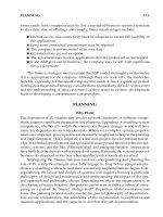
8.3 Protocol Architecture
A general protocol model, as depicted in Figure 8.2, is defined for all UTRAN
terrestrial interfaces. The protocol architecture is modularly composed of lay-
ers and planes that are logically independent of each other. Two main layers
are defined, namely, radio network layer (RNL) and transport network layer
(TNL). RNL contains all visible UTRAN-related issues, whereas TNL is com-
posed of standard transport technology selected to be used for UTRAN. Four
planes are defined: control plane (CP), user plane (UP), transport network
control plane (TNCP), and transport network user plane (TNUP).
CP isresponsible for all UMTS-specific controlsignaling, comprisingthe ap-
plication protocol and the signaling bearer. UP is responsible for transmission
and reception of all user-related information, such as coded voice, in a voice
call, or packets, in an Internet connection, comprising the data stream and
the data bearer. TNCP performs functions related to control signaling within
TNL, with the corresponding transactions carried out between CP and UP. It
isolates CP from UP sothat the communication between the application proto-
col, in CP, and the data bearer, in UP, is intermediated by the access link control
application part (ALCAP) in TNCP. ALCAP is specific for the particular
UP technology. In such a case, the application protocol can be completely
Radio Network
Layer
Application
Protocol
ALCAP
Data Stream
Data Bearer
Signaling
Bearer
Signaling
Bearer
Transport
Network
User Plane
Transport
Network Layer
Transport
Network
Control
Plane
Transport
Network
User Plane
User
Plane
Control
Plane
Physical Layer
FIGURE 8.2
Protocol architecture for UTRAN terrestrial interface.
© 2002 by CRC Press LLC
E:\Java for Engineers\VP Publication\Java for Engineers.vp
Thursday, April 25, 2002 9:27:36 AM
Color profile: Disabled
Composite Default screen
P1: FDJ
book CRC-Wireless November 21, 2001 12:26 Char Count= 282
independent of the technology selected for the data bearer. For preconfigured
data bearers, however, no ALCAP signaling transactions are necessary, in
which case TNCP becomes dispensable. It must be emphasized that ALCAP
is not used for setting up the signaling bearer for the application protocol
during real-time operations. In addition, the signaling bearer for ALCAP and
for the application protocol may be of different types. The signaling bearer for
ALCAP is always set up by O&M actions. TNUP is responsible for the trans-
port of user-related signaling and information comprising the data bearer, in
UP, and the signaling bearer, in CP. The data bearer is controlled by TNCP
during real-time operations, whereas the signaling bearer, in UP, is set up for
O&M actions.
The protocols and functions within each layer and plane are shown in
Table 8.1, where RNL User Plane in the second row refers to the Transport
TABLE 8.1
Protocol for the Various Interfaces
IuCS IuPS Iur Iub
RNL
RANAP RANAP RNSAP NBAP
Control
Plane
IuUPP IuUPP DCHFP DCHFP
CCHFP
RNL
User
Plane
RACHFP
FACHFP
PCHFP
DSCHFP
USCHFP
TNL
User
Plane
SCCP
MTP3b
SSCF-NNI
SSCOP
AAL5
ATM
SCCP
MTP3b M3UA
SSCF-NNI SCTP
SSCOP IP
AAL5
ATM
SCCP
MTP3b M3UA
SSCF-NNI SCTP
SSCOP IP
AAL5
ATM
SSCF-NNI
SSCOP
AAL5
ATM
TNL
Control
Plane
Q.2630.1
Q.2150.1
MTP3b
SSCF-NNI
SSCOP
AAL5
ATM
—
Q.2630.1
Q.2150.1
MTP3b M3UA
SSCF-NNI SCTP
SSCOP IP
AAL5
ATM
Q.2630.1
Q.2150.1
SSCF-NNI
SSCOP
AAL5
ATM
TNL
User
Plane
AAL2
ATM
GTP-U
UDP
IP
AAL5
ATM
AAL2
ATM
AAL2
ATM
© 2002 by CRC Press LLC
E:\Java for Engineers\VP Publication\Java for Engineers.vp
Thursday, April 25, 2002 9:27:36 AM
Color profile: Disabled
Composite Default screen
P1: FDJ
book CRC-Wireless November 21, 2001 12:26 Char Count= 282
Network User Plane indicated in the left side of Figure 8.2, and RNL User
Plane in the fourth row refers to the Transport Network User Plane indicated
in the right side of Figure 8.2. The protocols in Table 8.1 are explained next.
8.3.1 Radio Network Layer
As mentionedbefore, theradio network layer contains application protocol, in
CP, and data stream, in UP. Note that the application protocol is RANAP (RAN
application part) for IuCS and IuPS, RNSAP (RNS application part) for Iur,
and NBAP (Node B application part) for Iub. RANAP, RNSAP, and NBAP are
signaling protocols whose functions are basically those already mentioned
in the description of IuCS, IuPS, Iur, and Iub. The data stream comprises
the IuUPP (Iu User plane protocol) for IuCS and IuPS, DCHFP (dedicated
channel frame protocol) and CCHFP (control channel frame protocol) for Iur,
and DCHFP (dedicated channel frame protocol), RACHFP (random-access
channel frame protocol), FACHFP (forward access channel frame protocol),
PCHFP (paging channel frame protocol), DSCHFP (downlink shared channel
frame protocol), and USCHFP (uplink channel frame protocol) for Iub. IuUPP
conveys user data related to radio-access bearer (RAB).
It may operate either in the support mode or in the transparent mode. In
the first case, the protocol frames the user data into segment data units of
predefined size and performs control procedures for initialization and rate
control. In the second case, the protocol performs neither framing nor con-
trol and is applied to RABs not requiring such features. The various frame
protocols, namely, DCHFP, CCHFP, RACHFP, FACHFP, PCHFP, DSCHFP,
and USCHFP, handle the respective channels DCH (dedicated channel), CCH
(control channel), RACH (random-access channel), FACH (forward-access
channel), PCH (paging channel), DSCH (downlink shared common channel),
and USCH (uplink shared common channel), which are described later in this
chapter.
8.3.2 Transport Network Layer
As mentioned before, the RNL comprises the signaling bearer and the data
bearer, in TNUP, ALCAP, and signaling bearer, in TNCP. In TNCP, ALCAP
is implemented by means of Q.2630.1, and the adaptation is carried out by
Q.2150.1. A number of broadband signaling system 7 (BB SS7) protocols are
selected to implement the lower layers in CP and UP: SCCP (signaling connec-
tion control part), MTP3b (message transfer part), and SAAL-NNI (signaling
ATM adaptation layer for network-to-network interfaces). SAAL-NNI is, in
fact, split into SSCF (service-specific coordination function), SSCOP (service-
specific oriented protocol), and AAL 5 (ATM adaptation layer type 5) lay-
ers. SSCF and SSCOP layers respond for the signaling transport in ATM
© 2002 by CRC Press LLC
E:\Java for Engineers\VP Publication\Java for Engineers.vp
Thursday, April 25, 2002 9:27:36 AM
Color profile: Disabled
Composite Default screen
P1: FDJ
book CRC-Wireless November 21, 2001 12:26 Char Count= 282
networks, whereas AAL5 is responsible for the segmentation of data to com-
pose the ATM cells. AAL2 (ATM adaptation layer type 2) deals with transfer
of a service data unit with variable bit rate, transfer of timing information,
and indication of lost or errored information not recovered by type 2. As
an alternative to some BB SS7-based signaling bearers, an IP-based signaling
bearer is specified. They consist of M3UA (SS7 MTP3—user adaptation layer),
SCTP (simple control transmission protocol), and IP (Internet protocol), and
they are shown side-by-side with MTP3b, SSCF-NNI, and SSCOP in Table 8.1.
The multiplexing of packets on one or several AAL5 predefined virtual con-
nections (PVC) is provided by GTP-U (user plane part of the GPRS tunneling
protocol), which is responsible for identifying individual data flows. The data
flow uses UDP (user datagram protocol) connectionless transport and IP ad-
dressing. Note that all planes share a common ATM (asynchronous transfer
mode) transport. The physical layer constitutes the interface to the physical
medium (optical fiber, radio link, copper cable) and can be implemented with
standard off-the-shelf transmission technologies (SONET, STM1, E1).
8.4 Radio Interface Protocol Architecture
The handling of the radio bearer services is performed by the radio interface
protocols. Generally speaking, the UTRA radio interface protocol architec-
ture follows very closely the ITU-R protocol architecture as described in Ref-
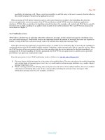
erence 4. The basic radio interface architecture encompassing the blocks and
protocols that are visible in UTRAN is illustrated in Figure 8.3. Only three lay-
ers, specifically, Layer 3, network layer, represented by its lowest sublayer;
Layer 2, data link layer; and Layer 1, physical layer, are of interest. The higher-
layer signaling, namely, mobility management and call control, belong to the
CN and are not described here. Note that Layer 3 and part of Layer 2 are
partitioned into CP and UP. The blocks in Figure 8.3 represent the instances
of the respective protocol and peer-to-peer communication are provided by
service access points (SAPs); some are shown in this figure in the form of
ellipses.
Layer 3 contains no elements in this radio interface for UP. In its CP, on
the other hand, it encompasses the radio resource control (RRC) that offers
services to the nonaccess stratum (higher layers) through SAPs, with these
SAPs used by the higher-layer protocols in the UE side and by Iu RANAP
in the UTRAN side. RRC encapsulates higher-layer signaling (mobility man-
agement, call control, session management, etc.) into RRC messages to be
transmitted over the radio interface. The control interfaces between RRC and
the lower layers are used to convey information and commands to perform
© 2002 by CRC Press LLC
E:\Java for Engineers\VP Publication\Java for Engineers.vp
Thursday, April 25, 2002 9:27:36 AM
Color profile: Disabled
Composite Default screen
P1: FDJ
book CRC-Wireless November 21, 2001 12:26 Char Count= 282
Signaling
RRC
Information
Control PDCP BMC
InformationSignaling
RLC RLC
Logical Channels
MAC
PHY
Transport Channels
Physical Channels
Layer 1
Layer 2
Layer 3
Control Plane User Plane
FIGURE 8.3
The basic radio interface architecture encompassing the blocks and protocols that are visible in
UTRAN.
configuration of the lower-layer protocol entities (logical channels, transport
channels, physical channels), to perform measurements, to report results of
measurements, and others.
Layer 2 is split into several sublayers, such as packet data convergence
protocol (PDCP), broadcast/multicast control (BMC), radio link control
(RLC), and medium access control (MAC). BMC is used to convey messages
© 2002 by CRC Press LLC
E:\Java for Engineers\VP Publication\Java for Engineers.vp
Thursday, April 25, 2002 9:27:36 AM
Color profile: Disabled
Composite Default screen
P1: FDJ
book CRC-Wireless November 21, 2001 12:26 Char Count= 282
originated from the cell broadcast center, including messages related to the
short message services. PDCP is responsible for header compression and is
specific to the packet-switched domain only. RLC provides services to RRC,
on the CP side, and (radio bearers) to PDCP, BMC, and other higher layers, on
the UP. These services are provided by means of SAPs and are called signaling
radio bearers in the CP and radio bearers for services that do not use either
PDCP or BMC in the UP. MAC offers services to RLC by means of SAPs.
Layer 1 contains the physical layer (PHY), which provides services to MAC
by means of SAPs.
The main SAPs shown in Figure 8.3 are logical channels, transport channels,
and physical channels. (The physical channels are not usually shown as SAPs
in the ITU documents; however, here they are described as such only for
didactic purposes.) The logical channels constitute the SAPs between RLC
and MAC and are characterized by the type of information transferred. They
are grouped into control channels and traffic channels. The transport channels
constitute the SAPs between MAC and PHY and are characterized by how
the information is transferred over the radio interface. The SAPs generated
by PHY are the physical channels to be transmitted over the air. They may be
defined in terms of carrier frequency, scrambling code, channelization code,
relative phase, time slot, frame, and multiframe.
Figure 8.4 illustrates how higher-layer service data units (SDUs) and pro-
tocol data units (PDUs) are segmented and multiplexed to transport blocks
RLC RLC
HL PDU HL PDU
RLC SDU RLC SDU
MAC MAC SDU MAC MAC SDU
CRC CRC
(RLC Segments)
(MAC PDU
s or
Transport Blocks)
Layer 1 Blocks
Segmentation
Reassembly
Higher Layer
(HL)
Layer 2
RLC
Layer 2
MAC
Layer 1
FIGURE 8.4
Data flow for a given service (nontransparent RLC and nontransparent MAC).
© 2002 by CRC Press LLC
E:\Java for Engineers\VP Publication\Java for Engineers.vp
Thursday, April 25, 2002 9:27:36 AM
Color profile: Disabled
Composite Default screen
P1: FDJ
book CRC-Wireless November 21, 2001 12:26 Char Count= 282
from Layer 3 through Layer 2 to be further treated by Layer 1. In Figure 8.4,
Layer 2 is assumed to operate in the nontransparent mode, in which case
protocol overhead is added to higher-layer PDUs. Next, the several blocks are
detailed.
8.4.1 Layer 3
As already mentioned, only the lowest sublayer of Layer 3, represented by
the RRC protocol, is visible in UTRAN.
Radio Resource Control
RRC is responsible for the CP signaling of Layer 3 between the UEs and the
radio interface. It interacts with the upper layers, such as those for the CN, and
performs functions as described next. (The last four functions are performed
in UTRA TDD only.)
r
Broadcast of System Information. RRC performs system information
broadcasting from the network to all UEs. Such information is pro-
vided by both the nonaccess stratum (CN) and the access stratum.
In the first case, the information may be cell specific and is transmit-
ted on a regular basis, whereas in the second case the information is
typically cell specific.
r
Establishment, Maintenance, and Release of an RRC Connection between
the UE and the RAN. An RRC connection is initiated, and then estab-
lished, by a request from higher layers at the UE side whenever the
first signaling connection for the UE is required. The RRC connec-
tion includes an optional cell reselection, an admission control, and a
Layer 2 signaling link connection.
r
Establishment, Reconfiguration, and Release of RABs. RRC establishes,
reconfigures, and releases RABs of the UP on request of higher layers.
The establishment and reconfiguration operations involve the real-
ization of admission control and selection of parameters describing
the RAB processing in Layer 2 and Layer 1.
r
Assignment, Reconfiguration, and Release of Radio Resources for the RRC
Connection. RRC controls the assignment, reconfiguration, and release
of the radio resources (e.g., codes) necessary for an RRC connection.
r
RRC Connection Mobility Functions. RRC is responsible for the evalu-
ation, decision, and execution of functions related to RRC connection
mobility during an established RRC connection. This includes han-
dover, preparation of handover to other systems, cell reselection, and
cell/paging area update procedures. These processes are based, for
example, on measurements carried out by the UE.
© 2002 by CRC Press LLC
E:\Java for Engineers\VP Publication\Java for Engineers.vp
Thursday, April 25, 2002 9:27:36 AM
Color profile: Disabled
Composite Default screen
P1: FDJ
book CRC-Wireless November 21, 2001 12:26 Char Count= 282
r
Paging/Notification. RRC is able to broadcast paging information from
the network to selected UEs as well as to initiate paging during an
established RRC connection.
r
Control of Requested QoS. RRC is responsible for the accomplishment of
the requested QoS for the access bearers. This includes the allocation
of the necessary radio resources for the specific purpose.
r
UE Measurement Reporting and Control of Reporting. RRC is responsi-
ble for the control of the measurements (what and how to measure
and how to report) performed by the UEs. It is also responsible for
reporting the measurements from the UEs to the network.
r
Outer Loop Power Control. RRC controls the setting of the target signal-
to-interference ratio of the closed-loop power control.
r
Control of Ciphering. RRC establishes procedures for setting (on/off)
ciphering between the UE and the RAN.
r
Initial Cell Selection and Reselection in Idle Mode. RRC is responsible
for the selection of the most suitable cell based on the idle mode
measurements and cell selection criteria.
r
Arbitration of the Radio Resource Allocation between Cells. RRC pro-
vides means of ensuring an optimal performance of the overall RAN
capacity.
r
Contention Resolution (UTRA TDD). RRC reallocates and releases radio
resources in the occurrence of collisions, as indicated by lower layers.
r
Slow DCA (UTRA TDD). RRC performs allocation of radio resources
based on long-term decision criteria (slow dynamic channel alloca-
tion, or slow DCA).
r
Timing Advance Control (UTRA TDD-3.84). RRC controls the operation
of timing advance.
r
Active UE Positioning (UTRA TDD-1.28). RRC determines the posi-
tion of the active UE according to the information received from the
physical layer.
8.4.2 Layer 2
Layer 2 is split into several sublayers including PDCP, BMC, RLC, and MAC.
Packet Data Convergence Protocol
PDCP is responsible for the transmission and reception of network PDUs. It
provides for the mapping from one network protocol to one RLC entity. In
the same way, it provides for compression (in the transmitting entity) and
decompression (in the receiving entity) of redundant network PDU control
© 2002 by CRC Press LLC
E:\Java for Engineers\VP Publication\Java for Engineers.vp
Thursday, April 25, 2002 9:27:36 AM
Color profile: Disabled
Composite Default screen
P1: FDJ
book CRC-Wireless November 21, 2001 12:26 Char Count= 282
information (header compression/decompression). It is present only in the
UP and its tasks are related to services within the PS domain only.
Broadcast/Multicast Control
BMC is responsible for broadcast/multicast transmission services on the ra-
dio interface for common user data, appearing only in the UP. The follow-
ing functionalities are handled by BMC: storage of cell broadcast messages,
scheduling of BMC messages, transmission of BMC messages to UEs, deliv-
ery of broadcast messages to the upper layer, monitoring of traffic volume,
and request of radio resource for cell broadcast services.
Radio Link Control
RLC provides for the establishment and release of RLC connections as well
as for QoS setting and notification to higher layers in case of unrecoverable
errors. It is responsible for data transfer, which may occur in three possible
modes, depending on the type of service: transparent mode, unacknowledged
mode, and acknowledged mode. The service provided by RLC in the CP is
called signaling radio bearers, whereas in the UP this is called radio bearer.
The communication of the RLC entities with the upper layer is provided by
means of SAPs: TM-SAP, for the transparent mode; UM-SAP, for the unac-
knowledged mode; and AM-SAP, for the acknowledged mode. The commu-
nication with the lower layer (MAC) is provided by means of SAPs known
as transport channels.
Transparent Mode. In the transparent mode, higher-layer PDUs are trans-
mitted without the inclusion of extra protocol information, with the exception
of the segmentation and reassembling functionalities.
Unacknowledged Mode. In the unacknowledged mode, higher-layer
PDUs are transmitted to the peer entity without guaranteeing delivery. The
following characteristics are applicable to the unacknowledged mode.
r
Immediate delivery. RLC delivers an SDU to the higher-layer receiving
entity upon arrival of the SDU at the receiver.
r
Unique delivery. RLC delivers each SDU to the higher-layer receiving
entity only once, using duplication detection function.
r
Detection of erroneous data. RLC delivers to the higher-layer receiv-
ing entity only those SDUs that are free from transmission errors.
This is achieved by means of the use of sequence-number check
functions.
Acknowledged Mode. In the acknowledged mode, higher-layer PDUs are
transmitted to the peer entity with guaranteed delivery and both in-sequence
© 2002 by CRC Press LLC
E:\Java for Engineers\VP Publication\Java for Engineers.vp
Thursday, April 25, 2002 9:27:36 AM
Color profile: Disabled
Composite Default screen
P1: FDJ
book CRC-Wireless November 21, 2001 12:26 Char Count= 282
and out-of-sequence deliveries are supported. In case of unsuccessful trans-
mission, the involved entity is notified. The following characteristics are ap-
plicable to the acknowledged mode.
r
Error-free delivery. RLC delivers error-free SDUs to the higher layers,
which is accomplished by means of retransmission of data blocks
whenever erroneous data are detected.
r
Unique delivery. RLC delivers each SDU to the higher-layer receiving
entity only once, using duplication detection function.
r
In-sequence delivery. RLC delivers SDUs to the higher-layer receiving
entity keepingthe same order asthat of SDUs submitted bythe higher-
layer entity to RLC.
r
Out-of-sequence delivery. RLC delivers SDUs to the higher-layer receiv-
ing entity without the need to keep the same order as that of SDUs
submitted by the higher-layer entity to RLC.
Medium Access Control
MAC handles data streams directed to it from RLC and RRC and provides
an unacknowledged transfer mode to the upper layers. The communication
between RLC and MAC is carried out through SAPs known as logical chan-
nels. In the same way, the communication between MAC and PHY is handled
through SAPs known as transport channels. More specifically, the following
tasks are performed by MAC.
r
Mapping of the different logical channels onto the appropriate Trans-
port Channels
r
Selection of appropriate transport formats for the transport channels
on the instantaneous source bit rate basis
r
Multiplexing of PDUs into transport blocks to be treated by PHY
r
Demultiplexing of PDUs from transport blocks delivered by PHY
r
Handling of priority issues for services to one UE according to infor-
mation from higher layers and PHY (e.g., available transmit power
level)
r
Handling of priority between UEs by means of dynamic scheduling
to improve spectrum efficiency
r
Monitoring of traffic volume to be used by RRC so that, based on
the detected volume, a reconfiguration of radio bearers or transport
channels may be triggered.
© 2002 by CRC Press LLC
E:\Java for Engineers\VP Publication\Java for Engineers.vp
Thursday, April 25, 2002 9:27:36 AM
Color profile: Disabled
Composite Default screen
P1: FDJ
book CRC-Wireless November 21, 2001 12:26 Char Count= 282
8.4.3 Layer 1
Layer 1 contains the physical layer that provides services to MAC by means
of SAPs known as transport channels. The SAPs generated by PHY are the
physical channels to be transmitted over the air. They are defined in terms
of carrier frequency, code, and relative phase for the UTRA FDD, and in
terms of carrier frequency, code, time slot, and multiframe for UTRA TDD.
The following functionalities are included within PHY. We note that some
functionalities are particular to one or another UTRA technology, whereas
others are common to the three of them. Next the functionalities in Layer 1
are cited. In the list that follows, those functionalities particular to any given
technology will be appropriately indicated.
r
Error detection on transport channels and indication to higher layers
r
Forward error control encoding/decoding of transport channels
r
Multiplexing of transport channels and demultiplexing of coded com-
posite transport channels
r
Rate matching
r
Mapping of coded composite transport channels onto physical chan-
nels
r
Power weighting and combining of physical channels
r
Modulation and spreading/demodulation and despreading of phys-
ical channels
r
Frequency and time (chip, bit, slot, frame) synchronization
r
Closed-loop power control
r
Radio frequency processing
r
Macrodiversity distribution/combining and soft handover execution
(UTRA FDD)
r
Macrodiversity distribution/combining and handover execution
(UTRA TDD-1.28)
r
Support of timing advance on uplink channels (UTRA TDD)
r
Radio characteristicsmeasurementsincluding frameerror rate, signal-
to-interference ratio, interference power levels, direction of arrival
(UTRA TDD-1.28) and indication to higher layers
r
Subframe segmentation (UTRA TDD-1.28)
r
Random-access process (UTRA TDD-1.28)
r
Dynamic channel allocation (UTRA TDD-1.28)
r
Handover measurements (UTRA TDD-1.28)
r
Uplink synchronization (UTRA TDD-1.28)
© 2002 by CRC Press LLC
E:\Java for Engineers\VP Publication\Java for Engineers.vp
Thursday, April 25, 2002 9:27:36 AM
Color profile: Disabled
Composite Default screen
P1: FDJ
book CRC-Wireless November 21, 2001 12:26 Char Count= 282
r
Beam-forming for both uplink and downlink—smart antennas
(UTRA TDD-1.28)
r
UE location/positioning (UTRA TDD-1.28)
The physical layer is described in more depth in several sections of this
chapter.
8.5 Logical Channels
Logical channels are SAPs located between RLC and MAC. They provide data
transfer services between these two entities. A logical channel is characterized
by the type of information it conveys. Broadly speaking, these channels can
be grouped into control channels and traffic channels. The logical channels
of the first group are used to convey CP information, whereas those in the
second group are used to convey UP information.
The following are the logical channels of the control channel group:
r
Broadcast Control Channel (BCCH). The BCCH is a downlink channel
used to broadcast system control information.
r
Common Control Channel (CCCH). The CCCH is a bidirectional channel
used to convey control information between the network and the UEs.
r
Dedicated Control Channel (DCCH). The DCCH is a point-to-point bidi-
rectional channel used to convey dedicated control information be-
tween the network and a UE. Such a channel is established during the
RRC connection establishment procedure.
r
Paging Control Channel (PCCH). The PCCH is a downlink channel used
to transmit paging information.
The following are the logical channels of the traffic channel group:
r
Control Traffic Channel (CTCH). The CTCH is a point-to-multipoint
unidirectional channel used to convey dedicated user information to
all UEs or to a specified group of UEs.
r
Dedicated Traffic Channel (DTCH). The DTCH is a point-to-point chan-
nel that can appear both in the downlink and uplink and is used to
convey information to one UE.
r
Shared Channel Control Channel (SHCCH)—UTRA TDD only. The
SHCCH is a bidirectional channel used to convey information to and
from shared transport channels.
© 2002 by CRC Press LLC
E:\Java for Engineers\VP Publication\Java for Engineers.vp
Thursday, April 25, 2002 9:27:36 AM
Color profile: Disabled
Composite Default screen
P1: FDJ
book CRC-Wireless November 21, 2001 12:26 Char Count= 282
8.6 Transport Channels and Indicators
Transport channels are SAPs located between MAC and PHY. They provide
data transfer services between these two entities. A transport channel is
characterized by how the information is transferred over the radio inter-
face and by the type of information it conveys. Broadly speaking, these
channels can be grouped into common channels and dedicated channels.
A transport channel of the first group is shared by all UEs or by a group
of UEs and contains an address field for address resolution purposes. The
transport channel of the second group is used by a single UE and is de-
fined by the physical channel; therefore, no specific address is needed for
the UE.
The following are the transport channels of the common channel group:
r
Broadcast Channel (BCH). The BCH is a downlink transport channel
used to broadcast system- and cell-specific information. Typically, the
BCH conveys information such as the available random-access codes,
available access slots, types of transmit diversity methods, etc. The
BCH is transmitted over the entire cell.
r
Forward Access Channel (FACH). The FACH is a downlink transport
channel used to convey control information to a UE whose location
is known to the system. The FACH may also carry short packet data.
There may exist one or more FACHs within a cell, one of them with
a bit rate low enough to be detected by all UEs. The FACH does
not make use of fast power control mechanisms. An in-band iden-
tification information is included to ensure correct reception of the
message.
r
Paging Channel (PCH). The PCH is a downlink transport channel used
to convey control information relevant to the paging procedure. A
paging message may be transmitted to one or more (up to a few
hundred) cells, depending on the system configuration.
r
Random-Access Channel (RACH). The RACH is an uplink transport
channel used to convey control information from the UE to the net-
work, typically for random-access purposes (requests to set up a con-
nection). It may also be used to carry short packet data from a UE
with messages lasting no longer than one or two frames.
r
Common Packet Channel (CPCH)—UTRA FDD. The CPCH is an uplink
transport channel used to convey short to medium-sized packet data
from a UE. This is, in fact, an extension of the RACH; the main dif-
ferences are the use of fast power control mechanisms, the longer
© 2002 by CRC Press LLC
E:\Java for Engineers\VP Publication\Java for Engineers.vp
Thursday, April 25, 2002 9:27:36 AM
Color profile: Disabled
Composite Default screen
P1: FDJ
book CRC-Wireless November 21, 2001 12:26 Char Count= 282
duration of transmission (several frames), and the channel status
monitoring for collision detection purposes.
r
Downlink Shared Channel (DSCH). The DSCH is a shared downlink
transport channel used to convey dedicated user data and control
information to several users. The DSCH resembles in many aspects
the FACH; the main differences are the use of fast power control as
well as variable bit rate on a frame-by-frame basis. It does not need
to be received within the whole cell area. It can employ different
modes of transmit antenna diversity methods and is associated with
a downlink dedicated channel.
r
Uplink Shared Channel (USCH)—UTRA TDD only. The USCH is a
shared uplink transport channel used to convey dedicated user data
and control information from several users. This is, in fact, an exten-
sion of the RACH; the main differences are the use of fast power
control mechanisms, the longer duration of transmission (several
frames), and the channel status monitoring for collision detection
purposes.
The following is the transport channel of the dedicated channel group:
r
Dedicated Channel (DCH). The DCH is the only transport channel
within the dedicated channel group. It is an uplink or downlink trans-
port channel conveying user information and control information.
Note that, as opposed to 2G systems in which these two types of
information are conveyed by different channels (traffic channel and
associated control channel), the DCH carries both service data (e.g.,
speech frames) and higher-layer control information (e.g., handover
commands, measurement reports). Thisis accomplished because vari-
able bit rate and service multiplexing are supported. The DCH sup-
ports the following: fast power control mechanisms; fast data rate
changed on a frame-by-frame basis; transmission to specific location
within the cell by use of adaptive antennas; and soft handover (UTRA
FDD).
Indicators, on the other hand, are low-level signaling entities that do not
use information blocks of the transport channels. They are of the Boolean
or three-valued type and are transmitted directly on the physical channels
known as indicator channels. The following are the specified indicators: ac-
quisition indicator (AI), access preamble indicator (API), channel assignment
indicator (CAI), collision detection indicator (CDI), page indicator (PI), and
status indicator (SI).
© 2002 by CRC Press LLC
E:\Java for Engineers\VP Publication\Java for Engineers.vp
Thursday, April 25, 2002 9:27:36 AM
Color profile: Disabled
Composite Default screen
P1: FDJ
book CRC-Wireless November 21, 2001 12:26 Char Count= 282
8.7 Physical Channels and Physical Signals
Physical channels may be defined in terms of carrier frequency, scrambling
code, channelization code, relative phase, time slot, subframe, frame, and
multiframe. Physical signals, on the other hand, are entities with the same
basic attributes as physical channels but with no transport channels or in-
dicators mapped to them. They may be associated with physical channels to
support functionalities of the physical channels. This section briefly describes
the functionalities of the physical channels, the details of their structures and
specific functionalities being given in a later subsection.
8.7.1 UTRA FDD Physical Channels
The following are the physical channels of UTRA FDD.
r
Common Pilot Channel (CPICH). The CPICH is a downlink physical
channel—unmodulated code channel—used as a phase reference for
the other downlink physical channels.
r
Synchronization Channel (SCH). The SCH is a downlink physical chan-
nel used for cell search purposes.
r
Primary Common Control Physical Channel (P-CCPCH). The P-CCPCH
is a downlink physical channel conveying control information at
30 kbit/s (constant bit rate).
r
Secondary Common Control Physical Channel (S-CCPCH). The S-CCPCH
is a downlink physical channel conveying control information at a
variable bit rate.
r
Acquisition Indicator Channel (AICH). The AICH is a downlink physi-
cal channel used to convey the acquisition indicator for the random-
access procedure. It is used to indicate the reception, at the base sta-
tion, of the random access channel signature sequence.
r
Paging Indicator Channel (PICH). The PICH is a downlink physical
channel used to convey page indicators to indicate the presence of a
page message on the PCH.
r
Physical Downlink Shared Channel (PDSCH). The PDSCH is a downlink
physical channel used to convey data and control information on a
common basis. It is used in association with the downlink dedicated
channel (downlink DCH) on which the information needed to decode
the PDSCH is carried to the UE.
r
Access Preamble Acquisition Indicator Channel (AP-AICH), Collision-
Detection/Channel-Assignment Indicator Channel (CD/CA-ICH), CPCH
Status Indicator Channel (CSICH). The AP-AICH, CD/CA-ICH, and
© 2002 by CRC Press LLC
E:\Java for Engineers\VP Publication\Java for Engineers.vp
Thursday, April 25, 2002 9:27:36 AM
Color profile: Disabled
Composite Default screen
P1: FDJ
book CRC-Wireless November 21, 2001 12:26 Char Count= 282
CSICH are downlink physical channels used for the uplink common
packet channel (CPCH) procedure. The CPCH procedure is described
later in this chapter.
r
Physical Random-Access Channel (PRACH). The PRACH is an uplink
physical channel used to convey control information for access pur-
poses. It also carries short user packets from the UE.
r
Physical Common Packet Channel (PCPCH). The PCPCH is an uplink
physical channel used to convey short to medium-sized user packets.
This is a fast-setup and fast-release channel. It is handled similarly to
the RACH reception by the physical layer at the base station.
r
Dedicated Physical Data Channel (DPDCH). This is an uplink and down-
link physical channel used to convey user information.
r
Dedicated Physical Control Channel (DPCCH). This is an uplink and
downlink physical channel used to convey control information.
8.7.2 UTRA TDD Physical Channels
The following are the physical channels of UTRA TDD. When no specific
reference is made to any particular technology, the physical channels as de-
scribed below are applicable to the two TDD technologies, UTRA TDD-3.84
and UTRA TDD-1.28.
r
Downlink Pilot Time Slot (DwPTS)—UTRA TDD-1.28. The DwPTS is
a downlink physical channel used as a phase reference for the other
downlink physical channels.
r
Uplink Pilot Time Slot (UpPTS)—UTRA TDD-1.28. The UpPTS is an
uplink physical channel used as a phase reference for the other uplink
physical channels.
r
Synchronization Channel (SCH). The SCH is a downlink physical chan-
nel used for cell search purposes.
r
Primary Common Control Physical Channel (P-CCPCH). The P-CCPCH
is a downlink physical channel conveying control information at
30 kbit/s (constant bit rate).
r
Secondary Common Control Physical Channel (S-CCPCH). The S-CCPCH
is a downlink physical channel conveying control information at a
variable bit rate.
r
Paging Indicator Channel (PICH)—UTRA TDD-3.84. The PICH is a
downlink physical channel used to convey page indicators to indi-
cate the presence of a page message on the PCH.
r
Physical Random-Access Channel (PRACH). The PRACH is an uplink
physical channel used to convey control information for access pur-
poses. It also carries short user packets from the UE.
© 2002 by CRC Press LLC
E:\Java for Engineers\VP Publication\Java for Engineers.vp
Thursday, April 25, 2002 9:27:36 AM
Color profile: Disabled
Composite Default screen
P1: FDJ
book CRC-Wireless November 21, 2001 12:26 Char Count= 282
r
Physical Downlink Shared Channel (PDSCH). The PDSCH is a downlink
physical channel used to convey data and control information on a
common basis. It is used in association with the downlink dedicated
channel (downlink DCH) on which the information needed to decode
the PDSCH is carried to the UE.
r
Physical Uplink Shared Channel (PUSCH). The PUSCH is an uplink
physical channel used to convey short to medium-sized user pack-
ets. This is a fast-setup and fast-release channel handled similarly to
RACH reception by the physical layer at the base station.
r
Dedicated Physical Channel (DPCH). This is an uplink and downlink
physical channel used to convey user information and control
information.
8.8 Mapping of Channels
Figure 8.5 illustrates the possible mapping of logical channels, transport chan-
nels, and physical channels. In Figure 8.5, AP-CPCH indicates the four down-
link physical channels used for CPCH access procedure.
DCCH
DTCH
CTCH
SHCCH
(TDD)
CCCHBCCHPCCH
CPCH
(FDD)
DSCH
USCH
(TDD)
FACHRACHBCHPCH DCH
DPDCH
DPCCH
(FDD)
PCPCH
(FDD)
PDSCH
PUSCH
(TDD)
S-CCPCHPRACHP-CCPCH
DCH
(TDD)
CPCH
(FDD)
DSCH
USCH
(TDD)
FACHRACHBCHPCH DCH
DCCH
DTCH
CTCH
SHCCH
(TDD)
CCCHBCCHPCCH
AP-CPCH
(FDD)
AICH
(FDD)
PICH
UpPTS
(TDD
1.28)
DwPTS
(TDD
1.28)
SCHCPICH
UE
UTRAN
Logical
Channels
Transport
Channels
Physical
Channels
Logical
Channels
Transport
Channels
FIGURE 8.5
Mapping of logical channels, transport channels, and physical channels.
© 2002 by CRC Press LLC
E:\Java for Engineers\VP Publication\Java for Engineers.vp
Thursday, April 25, 2002 9:27:36 AM
Color profile: Disabled
Composite Default screen
P1: FDJ
book CRC-Wireless November 21, 2001 12:26 Char Count= 282
8.9 Physical Layer Transmission Chain
Figures 8.6 and 8.7 illustrate the physical layer transmission chain for UP
data, respectively, for uplink and downlink. Each chain starts at the transport
channel level and ends at the physical channel level. Note how several trans-
port channels may be multiplexed onto one or more dedicated physical data
channels. The transmission chain is identical in both directions for UTRA
TDD and slightly different for UTRA FDD.
In the UTRA FDD uplink direction, the data stream is continuous with
services multiplexed dynamically. The symbols are sent with equal power
for all services, which implies that the relative rates for the different services
must be adjusted to balance the power level requirements for the channel
symbols. In the UTRA FDD downlink direction, the data stream is given
discontinuous transmission (DTX) capability. In this case, DTX indication bits
are inserted, but not transmitted over the air, and they inform the transmitter
the bit positions at which the transmission should be turned off. The insertion
point of the DTX indication bits depends on whether fixed or flexible positions
of the transport channels in the radio frame is used. The decision whether
fixed or flexible positions are used during a connection is the responsibility
of UTRAN. There are two possible DTX insertion stages. The first insertion
occurs only if the positions of the transport channels in the radio frame are
fixed. In the second insertion, the indication bits are placed at the end of the
radio frame. In such a case, because an interleaving step occurs, DTX will
be distributed over all slots after the second interleaving. The transmission
chain illustrated in Figures 8.6 and in 8.7 is detailed next.
The transport block, received from higher layers, is given error detec-
tion capability by means of cyclic redundancy check (CRC) attachment. De-
pending on the service requirements, as signaled from higher layers, the
CRC attachment can take the length of 0, 8, 12, 16, or 24 bits, with the
cyclic generator polynomials for the nonzero lengths, respectively, given
by
G
CRC8
(
D
)
= D
8
+ D
7
+ D
4
+ D
3
+ D +1
G
CRC12
(
D
)
= D
12
+ D
11
+ D
3
+ D
2
+ D +1
G
CRC16
(
D
)
= D
16
+ D
12
+ D
5
+1
G
CRC24
(
D
)
= D
24
+ D
23
+ D
6
+ D
5
+ D +1
All transport blocks in a transmission time interval (TTI) are serially con-
catenated. If the size of a TTI, measured in number of bits, is larger than
the maximum size of a code block under consideration, then code block
© 2002 by CRC Press LLC
E:\Java for Engineers\VP Publication\Java for Engineers.vp
Thursday, April 25, 2002 9:27:36 AM
Color profile: Disabled
Composite Default screen
P1: FDJ
book CRC-Wireless November 21, 2001 12:26 Char Count= 282
Channel Coding
CRC Attachment
Transport Block Concatenation
Code Block Segmentation
Radio Frame Equalization
First Interleaving
Radio Frame Segmentation
Rate Matching
Transport Channels Multiplexing
Physical Channel Segmentation
Second
Interleaving
Subframe
Segmentation
(TDD - 1.28)
Physical
Channel
Mapping
Physical Channel 1 Physical Channel n
FIGURE 8.6
Physical layer transmission chain for UP data for uplink.
© 2002 by CRC Press LLC
E:\Java for Engineers\VP Publication\Java for Engineers.vp
Thursday, April 25, 2002 9:27:36 AM
Color profile: Disabled
Composite Default screen
P1: FDJ
book CRC-Wireless November 21, 2001 12:26 Char Count= 282
Channel Coding
CRC Attachment
Transport Block Concatenation
Code Block Segmentation
First Insertion of DTX Indication
First Interleaving
Radio Frame Segmentation
Rate Matching
Transport Channels Multiplexing
Physical Channel Segmentation
Second
Interleaving
Physical
Channel
Mapping
Physical Channel 1 Physical Channel n
Second Insertion of DTX Indication
FIGURE 8.7
Physical layer transmission chain for UP data for downlink.
segmentation is carried out after the concatenation has been performed. The
maximum size of the code blocks varies depending on the coding scheme
used in the transport channel.
After concatenation/segmentation, the code blocks are delivered to the
channel coding block, where the following coding schemes can be applied to
© 2002 by CRC Press LLC
E:\Java for Engineers\VP Publication\Java for Engineers.vp
Thursday, April 25, 2002 9:27:36 AM
Color profile: Disabled
Composite Default screen
P1: FDJ
book CRC-Wireless November 21, 2001 12:26 Char Count= 282
the transport channels: convolutional coding, turbo coding, or no coding.
Real-time services make use of forward error correction (FEC) encoding,
whereas non-real-time services make use of a combination of FEC and au-
tomatic repeat request (ARQ). The possible convolutional coding rates are
1/2or1/3 whereas the turbo code rate is 1/3. In the 1/2 rate case, the genera-
tor polynomials are
G
0
(
D
)
= D
8
+ D
6
+ D
5
+ D
4
+1
for output 0 (G
0
(
D
)
= 561, in octal form), and
G
1
(
D
)
= D
8
+ D
7
+ D
6
+ D
5
+ D
3
+ D +1
for output 1 (G
1
(
D
)
= 753, in octal form). In the 1/3 rate case, the generator
polynomials are
G
0
(
D
)
= D
8
+ D
6
+ D
5
+ D
3
+ D
2
+ D +1
for output 0 (G
0
(
D
)
= 557, in octal form),
G
1
(
D
)
= D
8
+ D
7
+ D
5
+ D
4
+ D +1
for output 1 (G
1
(
D
)
= 663, in octal form) and
G
2
(
D
)
= D
8
+ D
7
+ D
6
+ D
3
+1
for output 2 (G
2
(
D
)
= 711, in octal form). Turbo encoding is used for data serv-
ices requiring quality of service—bit error rate (BER)—within the range from
10
−3
to 10
−6
. For such a purpose, parallel concatenated convolutional code
(PCCC) with eight-state constituent encoders is used. The transfer function
of the eight-state constituent code for PCCC is
G
(
D
)
=
1,
1+D + D
3
1+D
2
+ D
3
The initial value of the shift registers of the PCCC encoders is set to all zero.
Its output is punctured to produce coded bits corresponding to the desired
1/3 code rate.
The radio frame equalization function concerns the frame size equalization,
which ensures that the output can be segmented into equal-sized segments
© 2002 by CRC Press LLC
E:\Java for Engineers\VP Publication\Java for Engineers.vp
Thursday, April 25, 2002 9:27:36 AM
Color profile: Disabled
Composite Default screen
P1: FDJ
book CRC-Wireless November 21, 2001 12:26 Char Count= 282
to be transmitted in the TTI of the respective transport channel. Frame size
equalization is carried out by means of padding the input bit sequence and
is performed only in the uplink.
The first interleaving, or interframe interleaving, performs a block inter-
leaving with intercolumn permutation and possible interleaving depths of
10, 20, 40, and 80 ms.
After the first interleaving is performed, and if the transmission time in-
terval is longer than 10 ms, the bit sequence is segmented and mapped onto
consecutive equal-sized radio frames. Note that, following radio frame size
equalization in the uplink and rate matching in the downlink, the input bit
sequence length is guaranteed to have an integer multiple of the number of
radio frames in the respective TTI. When the TTI is longer than 10 ms, the
input bit sequence is segmented and mapped onto an integer number of con-
secutive frames. The number of bits on a transport channel may vary between
different TTIs. In the downlink, for example, the transmission is interrupted
if the number of bits is smaller than the maximum.
To guarantee that, after transport channels multiplexing, the total bit rate is
identical to the total channel bit rate of the allocated dedicated physical chan-
nels, rate matching is performed. Rate matching is used to accommodate the
number of bits to be transmitted within the frame. This is accomplished by
repeating or puncturing bits of the transport channels. The rate-matching at-
tribute is semistatic and can only be changed through higher-layer signaling.
In the uplink direction, rate matching is a dynamic operation varying on a
frame-by-frame basis. The multiplexing of several transport channels onto
the same frame involves a rate-matching operation to guarantee the use of
all symbols. In this case, a decrease of a symbol rate of a transport channel
implies an increase of the symbol rate of another transport channel. Note
that, by adjusting the rate-matching attribute, the quality of different ser-
vices can be adjusted so that a near-equal symbol power level requirement is
reached.
After rate matching, and at every 10 ms, each radio frame from each trans-
port channel is delivered to the transport channel multiplexing block. These
radio frames are serially multiplexed to yield a coded composite transport
channel (CCTrCH).
In case more than one physical channel is required for the transmission of
the CCTrCH, a physical channel segmentation is performed so that data are
evenly distributed among the respective physical channels.
A second interleaving is then applied jointly to all data bits transmitted dur-
ing one frame, or separately within each time slot (for UTRA TDD) onto which
the CCTrCH is mapped. The selection of the second interleaving scheme is
controlled by a higher layer.
The final step in this transmission chain is the mapping of bits from the
second interleaver onto physical channels.
© 2002 by CRC Press LLC
E:\Java for Engineers\VP Publication\Java for Engineers.vp
Thursday, April 25, 2002 9:27:36 AM
Color profile: Disabled
Composite Default screen
P1: FDJ
book CRC-Wireless November 21, 2001 12:26 Char Count= 282
The multiplexing of different transport channels onto one CCTrCh and the
mapping of one CCTrCH onto physical channels follow some basic rules:
r
Transport channels multiplexed onto one CCTrCH should have co-
ordinated timings. This means that transport blocks arriving on dif-
ferent transport channels of potentially different transmission time
intervals shall have aligned transmission time instants. If the possi-
ble transmission time instants are multiple of t ms, then a transport
channel of k×t ms will occupy k transmission time intervals starting
at the allowed transmission time instants.
r
Different CCTrCHs cannot be mapped onto the same physical chan-
nel.
r
One CCTrCH is mapped onto one or several physical channels.
r
Dedicated transport channels and common transport channels cannot
be multiplexed into the same CCTrCH.
r
Among the common transport channels only FACH and PCH may
belong to the same CCTrCH.
r
A CCTrCH carrying a BCH shall notcarry anyother transportchannel.
r
A CCTrCH carrying a RACH shall not carry any other transport
channel.
Note that there are two types of CCTrCH: CCTrCH of the dedicated type,
corresponding to the result of coding and multiplexing of one or more DCHs;
and CCTrCH of the common type, corresponding to the result of the coding
and multiplexing of a common channel, namely, RACH and USCH in the
uplink, and DSCH, BCH, FACH, or PCH in the downlink.
8.10 Channel and Frame Structures
In this section, the frame structure and the channel structure of UTRA are
described. Special attention is given to the UTRA FDD technology, where
a detailed description of these structures is provided. These items are only
superficially explored for the UTRA TDD technologies.
8.10.1 UTRA FDD Uplink Physical Channels
This subsection describes the various UTRA FDD uplink physical channels.
© 2002 by CRC Press LLC
E:\Java for Engineers\VP Publication\Java for Engineers.vp
Thursday, April 25, 2002 9:27:36 AM
Color profile: Disabled
Composite Default screen