WIRELESS TECHNOLOGYProtocols, Standards, and Techniques pdf phần 10 pdf
Bạn đang xem bản rút gọn của tài liệu. Xem và tải ngay bản đầy đủ của tài liệu tại đây (1.34 MB, 60 trang )
P1: FDJ
book CRC-Wireless November 18, 2001 14:38 Char Count= 264
required. Their Walsh codes are not predetermined and are assigned on a
demand basis.
In the description of the channels, a signal point mapping block is present
in all channel structures. The signal point mapping block maps the binary
levels 0 and 1 onto +1 and −1, respectively.
9.10.1 Forward Pilot Channel
TheF-PICHisanunmodulated,direct-sequencespreadspectrumsignaltrans-
mitted continuously by each base station, unless the base station is classified
as a hopping pilot beacon base station. The F-PICH prior to Walsh spreading
contains a sequence of zeros. Such a sequence is combined with the Walsh
code 0, length 64 (W
64
0
), which also encompasses a sequence of zeros. The
F-PICH allows a mobile station to acquire the timing of the forward CDMA
channel, provides a phase reference for coherent demodulation, and provides
means for signal strength comparisons between base stations for handoff pur-
poses. Only one F-PICH is used per forward CDMA channel for both SR 1
and SR 3. Figure 9.16 depicts the F-PICH structure for both SR 1 and SR 3. The
outputs S
I
and S
Q
shown in Figure 9.16 constitute the inputs of the DEMUX
blocks shown in Figure 9.8, for SR 1, and Figure 9.11, for SR 3.
9.10.2 Forward Transmit Diversity Pilot Channel
The F-TDPICH is an unmodulated, direct-sequence spread spectrum signal
transmitted continuously by a CDMA base station. It is used to support
forward-link transmit diversity. F-PICH and F-TDPICH provide phase ref-
erences for coherent demodulation of those forward-link CDMA channels
deploying transmit diversity. The transmission of F-TDPICH does not imply
a decrease of the transmit power of F-PICH. On the contrary, the base station
should continue to use sufficient power on the F-PICH to ensure that a mobile
station is able to acquire and estimate the forward CDMA channel without
Signal Point
Mapping
and Gain
All 0s
Pilot
Channels
Data
0
FIGURE 9.16
Forward pilot channels structure.
© 2002 by CRC Press LLC
E:\Java for Engineers\VP Publication\Java for Engineers.vp
Thursday, April 25, 2002 9:27:36 AM
Color profile: Disabled
Composite Default screen
P1: FDJ
book CRC-Wireless November 18, 2001 14:38 Char Count= 264
using energy from the F-TDPICH. F-TDPICH is transmitted with Walsh code
16, length 128 (W
128
16
). Only one F-TDPICH is used per forward CDMA chan-
nel, with this channel provided in SR 1 and not in SR 3. Its configuration is
the same as that shown in Figure 9.16.
9.10.3 Forward Auxiliary Pilot Channel
The F-APICH is used for forward-link spot beam-forming purposes in net-
works with smart antennas. The utilization of F-APICH provides for high data
rate applications in specific locations. It is used as a phase reference for co-
herent demodulation of those forward-link CDMA channels associated with
it. Zero or more F-APICHs can be transmitted by the base station on an active
forward CDMA channel. An F-APICH can be shared by a number of dis-
tinct mobiles in the same spot beam. The locations served by F-APICHs may
vary, as required. Spot beams can be used to increase coverage of a particular
geographic point or to increase capacity of hot spots. Systems making use
of such an option must provide for separate forward-link channels for the
specific area. F-APICHs are code-multiplexed with other forward-link chan-
nels. This obviously reduces the number of Walsh codes available for traffic.
To reduce this effect, long Walsh codes are used for these channels. The F-
APICH is transmitted with Walsh code n, length N (W
N
n
), where N ≤ 512 and
1 ≤ n ≤ N − 1. The Walsh code number and Walsh code length are deter-
mined by the base station. This channel is used in SR 1 and in SR 3, with the
number of them per forward CDMA channel not specified. Its configuration
is the same as that shown in Figure 9.16.
9.10.4 Forward Auxiliary Transmit Diversity Pilot Channel
The F-ATDPICH is a transmit diversity pilot channel associated with an F-
APICH. F-ATDPICH and F-APICH provide phase references for coherent
demodulation of those forward-link CDMA channels associated with the
F-APICH. F-ATDPICH is transmitted with Walsh code n + N/2, length N
(W
N
n + N/2
), where N ≤ 512 and 1 ≤ n ≤ N − 1. The Walsh code number and
Walsh code length are determined by the base station. This channel is used
in SR 1 and not in SR 3, with the number per forward CDMA channel not
specified. Its configuration is the same as that shown in Figure 9.16.
9.10.5 Forward Dedicated Auxiliary Pilot Channel
The F-DAPICH is anoptional auxiliary pilot channel usedon a dedicated basis
for a given mobile station. It is an unmodulated, direct-sequence spread spec-
trum signal transmitted continuously by a CDMA base station. F-DAPICH is
code-multiplexed with other forward-link channels. Its Walsh code number
© 2002 by CRC Press LLC
E:\Java for Engineers\VP Publication\Java for Engineers.vp
Thursday, April 25, 2002 9:27:36 AM
Color profile: Disabled
Composite Default screen
P1: FDJ
book CRC-Wireless November 18, 2001 14:38 Char Count= 264
and the corresponding Walsh code length are determined by the base station.
F-DAPICH is employed aiming at antenna beam-forming applications and
beam-steering techniques to increase the coverage or date rate for a particular
mobile station. Note that F-DAPICH cannot be considered a common channel.
This channel is used for periodic channel estimations so that the forward-link
antenna pattern can be adequately adjusted for better performance.
9.10.6 Forward Synchronization Channel
TheF-SYNCHisacodechannelconveyingthesynchronizationmessage.Such
a message is used by the mobile station to acquire initial time synchroniza-
tion. F-SYNCH is implemented in cdma2000 as it is in cdmaOne. F-SYNCH
is a low-powered, low-rate channel (1.2 kbit/s) that contains a single, re-
peating message referred to as the sync channel message. This message is
continuously broadcast by the cell and contains parameters, such as system
identification number, network identification number, cell or sector Short PN
offset, system time, long code state, and paging channel data rate. This chan-
nel is transmitted with Walsh code 32, length 64 (W
64
32
) for both SR 1 and SR
3, one per forward CDMA channel. The F-SYNCH structure is depicted in
Figure 9.17.
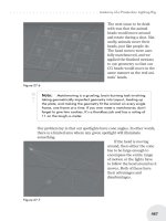
9.10.7 Forward Paging Channel
The F-PCH is a code channel used for transmission of control information and
pages from a base station to the mobile stations. It conveys system overhead
Signal Point
Mapping
and Gain
4.8 ksymb/s
I
S
Q
S
0
(SR1)
Block
Interleaver
(16x8)
Symbol
Repetition
(x2)
Convolutional
Encoder
(1/2, 9)
1.2 kbit/s
32 bits/
26.666 ms frame
Sync
Channel
Data
Modulation
Symbol
(SR3)
To Forward
Transmission
Block i
i = 1, 2, 3
or
FIGURE 9.17
Forward synchronization channel structure.
© 2002 by CRC Press LLC
E:\Java for Engineers\VP Publication\Java for Engineers.vp
Thursday, April 25, 2002 9:27:36 AM
Color profile: Disabled
Composite Default screen
P1: FDJ
book CRC-Wireless November 18, 2001 14:38 Char Count= 264
Paging
Channel
Data
Convolutional
Encoder
(1/2, 9)
4.8 ksymb/s
9.6 ksymb/s
Symbol
Repetition
(x2)
(x1)
Block
Interleaver
(24x16)
+
9.6 ksymb/s
19.2 ksymb/s 19.2 ksymb/s
Long Code
Generator
Decimator
64:1
1.2288 Mchip/s
Long Code
Mask for
Paging
Channel k
19.2 ksymb/s
Signal Point
Mapping
and Gain
I
S
Q
S
0
Modulation
Symbol
96 bits/20 ms
192 bits/20 ms
FIGURE 9.18
Forward paging channel structure.
information and mobile station specific messages. It is identical to the paging
channel of cdmaOne. F-PCH transmits in the slotted mode, each slot with
80 ms of duration. Mobile stations, on the other hand, may operate in either
the slotted mode or nonslotted mode. Paging and control messages for a mo-
bile station operating in the nonslotted mode can be conveyed in any of the
F-PCH slots. Therefore, the nonslotted mode of operation requires the mo-
bile station to monitor all the slots. The slotted mode of operation requires
the assignment of a specific slot to the mobile station; this feature is used to
save battery. There may be as many as seven F-PCHs per forward CDMA in
SR 1. SR 3 does provide for F-PCH. The primary F-PCH is assigned Walsh
code number 1, length 64 (W
64
1
), with the remaining F-PCHs of the same
length and numbered sequentially from 2 to 7 (W
64
2−7
). These channels operate
at full rate (9.6 kbit/s) and at half rate (4.8 kbit/s). The F-PCH is illustrated
in Figure 9.18.
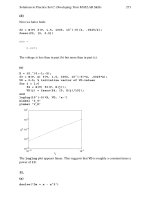
9.10.8 Forward Broadcast Control Channel
The F-BCCH is a code channel used for transmission of control information
from a base station to the mobile stations. It conveys broadcast overhead mes-
sages and short message service broadcast messages. (Mobile specific mes-
sages are not sent on this channel, but on the F-CCCH.) There may be as many
aseightF-BCCHsperforwardCDMAinbothSR1andSR3.ThespecificWalsh
code used is determined by the base station and such information is conveyed
by the F-SYNCH. In both SR 1 and SR 3, 744 bits are transmitted in slots of 40,
80, or 160 ms. The 744 bits together with 16 quality indicator bits and eight
encoder tail bits lead to data rates of, respectively, 19.2, 9.6, and 4.8 kbit/s.
Different Walsh codes are used for the different F-BCCH structures. The
F-BCCH structure is illustrated in Figure 9.19.
© 2002 by CRC Press LLC
E:\Java for Engineers\VP Publication\Java for Engineers.vp
Thursday, April 25, 2002 9:27:36 AM
Color profile: Disabled
Composite Default screen
P1: FDJ
book CRC-Wireless November 18, 2001 14:38 Char Count= 264
Broadcast Control
Channel Data
(744 bits per
40, 80, or 160 ms)
Encoder Tail
(+8 bits)
Convolutional
Encoder
19.2, 9.6, or
4.8 ksymb/s
Long Code
Generator
Long Code
Mask
+
Block
Interleaver
Sequence
Repetition
(x1, x2, or x4)
Signal Point
Mapping
and Gain
Scrambling
Bit Extractor
Scrambling Bit
Repetition
Modulation Symbol
S
Frame Quality
Indicator
(+16 bits)
FIGURE 9.19
Forward broadcast control channel structure.
F-BCCH for SR 1
The long code generator for the SR 1 F-BCCH operates with a chip rate of
1.2288 Mchip/s. The I/Q Scrambling Bit Extractor block extracts the I and
Q pairs at a rate given by the modulation symbol rate divided by twice the
scrambling bit repetition factor. The scrambling repetition factor, in the scram-
bling repetition bit block, is equal to 1 for the non-TD mode and 2 for the
TD mode. Two operation options can be found for the F-BCCH, depend-
ing on the convolutional encoder used. One of the options uses a 1/4-rate
convolutional encoder with constraint length of 9. The other option uses a
1/2-rate convolutional encoder with constraint length of 9. In the first case,
the block interleaver is of 3,072 symbols, whereas in the second case the
block interleaver is of 1,535 symbols. The modulation symbol rates (rate af-
ter the block interleaver) are, respectively, 76.8 and 38.4 ksymb/s. The Walsh
codes in the respective cases are numbered n with lengths 32 (W
32
n
) and 64
(W
64
n
).
F-BCCH for SR 3
The long code generator for the SR 3 F-BCCH operates with a chip rate of
3.6864 Mchip/s. The I/Q scrambling bit extractor block extracts the I and Q
pairs at a rate given by the modulation symbol rate divided by the scram-
bling bit repetition factor multiplied by 6. The scrambling repetition factor,
in the scrambling repetition bit block, is equal to 3. A 1/3-rate convolutional
encoder with constraint length of 9 is used, in which case the block interleaver
© 2002 by CRC Press LLC
E:\Java for Engineers\VP Publication\Java for Engineers.vp
Thursday, April 25, 2002 9:27:36 AM
Color profile: Disabled
Composite Default screen
P1: FDJ
book CRC-Wireless November 18, 2001 14:38 Char Count= 264
operates with 2,304 symbols. The modulation symbol rate (rate after the block
interleaver) is, therefore, 57.6 ksymb/s. The Walsh codes are numbered n with
lengths 128 (W
128
n
).
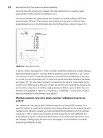
9.10.9 Forward Quick Paging Channel
The F-QPCH is an uncoded, spread, and on-off-keying modulated spread
spectrum signal used in support of the operation of F-PCH and F-CCCH. It is
sentbythebasestationtoinformmobilestationsoperatingintheslottedmode
whether to receive the F-PCH or the F-CCCH starting in their respective next
frames. The use of F-QPCH reduces the time a mobile station needs to process
received data, resulting in increased battery life. This is because the mobile
does not have to activate its processors to understand the messages of the
channel. Indicators are used to facilitate the task. These indicators are recog-
nized by threshold-based detection. Therefore, if there is no new message for
the mobile station in the F-PCH or in the F-CCCH, it does not have to activate
its processors to decode the message in the assigned slot. Data rates of 4.8 and
2.4 ksymb/s can be used. Slots of 80 ms are specified to convey two indicators
per mobile in each slot. The resulting indicator rates are, respectively, 9.6 and
4.8 ksymb/s. The F-QPCH slots are aligned to initiate 20 ms before the start
of the zero-offset pilot PN sequence. In SR 1, the symbols are repeated two or
four times to yield a constant rate of 19.2 ksymb/s. In SR 3, the repetition fac-
tors are, respectively, 3 and 6, leading to a transmission rate of 28.8 ksymb/s.
One of the indicators, the paging indicator, serves the purpose of instructing
a slotted mode mobile station to monitor the F-PCH or the F-CCCH starting
in the next frame. The other indicator, the configuration change indicator,
serves the purpose of instructing a slotted-mode mobile station to monitor
the F-PCH, the F-CCCH, and the F-BCCH, after an idle handoff has been per-
formed. This is carried out to determine whether the mobile station should
update its stored parameters, in case the cell configuration parameters have
changed. There may be up to three F-QPCHs per forward CDMA both in
SR 1 and SR 3. These channels are assigned the Walsh codes numbered 48,
80, and 112, and length 128 (W
128
48
, W
128
80
, and W
128
112
, respectively). The F-QPCH
structure is illustrated in Figure 9.20.
9.10.10 Forward Common Control Channel
The F-CCCH conveys Layer 3 and MAC control messages from a base station
to one or more mobile stations. The coding parameters are identical to those of
F-PCH. It essentially replaces the F-PCHs for higher data rate configurations
carrying mobile station specific messages. Therefore, F-CCCHs are effectively
paging channels optimized for packet services, in which case F-PCHs are not
© 2002 by CRC Press LLC
E:\Java for Engineers\VP Publication\Java for Engineers.vp
Thursday, April 25, 2002 9:27:36 AM
Color profile: Disabled
Composite Default screen
P1: FDJ
book CRC-Wireless November 18, 2001 14:38 Char Count= 264
Signal Point
Mapping
and Gain
S
Symbol
Repetition
Indicator Rate 9.6 or 4.8 ksymb/s
Data Rate 4.8 or 2.4 ksymb/s
Quick Paging
Channel Data
FIGURE 9.20
Forward quick paging channel structure.
used. An F-CCCH contains slots of 80-ms duration accommodating 20-, 10-,
or 5-ms frames. Paging and control messages for a mobile station operating in
the nonslotted mode can be conveyed in any of the F-CCCH slots. Therefore,
the nonslotted mode of operation requires the mobile station to monitor all the
slots. The slotted mode of operation requires the assignment of a specific slot
to the mobile station, a feature used to save battery. Although the data rate of
the F-CCCHs may vary from frame to frame, for any given frame transmitted
to the mobile station the data rate of that frame is previously known to that
mobile station. There may be as many as seven F-CCCHs per forward CDMA
in both SR 1 and SR 3. The specific Walsh code used is determined by the
base station and such information is conveyed by the F-SYNCH. In both SR 1
and SR 3, three data rates are possible: 9.6, 19.2, and 38.4 kbit/s. The F-CCCH
structure is illustrated in Figure 9.21.
Common Control
Channel Data
Encoder Tail
(+8 bits)
Convolutional
Encoder
Long Code
Generator
Long
Code
Mask
+
Block
Interleaver
Signal Point
Mapping
and Gain
Scrambling
Bit Extractor
Scrambling Bit
Repetition
Modulation Symbol
S
Frame Quality
Indicator
(+bits)
E
A
B
C D
FIGURE 9.21
Forward common control channel structure.
© 2002 by CRC Press LLC
E:\Java for Engineers\VP Publication\Java for Engineers.vp
Thursday, April 25, 2002 9:27:36 AM
Color profile: Disabled
Composite Default screen
P1: FDJ
book CRC-Wireless November 18, 2001 14:38 Char Count= 264
F-CCCH for SR 1
The long code generator for the SR 1 F-CCCH operates with a chip rate of
1.2288 Mchip/s. The I/Q scrambling bit extractor block extracts the I and
Q pairs at a rate given by the modulation symbol rate divided by twice the
scrambling bit repetition factor. The scrambling repetition factor, in the scram-
bling repetition bit block, is equal to one for the non-TD mode and two for the
TD mode. Two operation options can be found for the F-BCCH, depending
on the convolutional encoder used. One of the options uses a 1 /4-rate convo-
lutional encoder with constraint length of 9. The other option uses a 1/2-rate
convolutional encoder with constraint length of 9. The Walsh codes in the
respective cases for the respective transmission rates are W
16
n
, W
32
n
, and W
64
n
,
and W
32
n
, W
64
n
, and W
128
n
. The various parameters for the points (A, B, C, D, E)
shown in Figure 9.21 are specified in Table 9.9.
F-CCCH for SR 3
The long code generator for the SR 3 F-CCCH operates with a chip rate of
3.6864 Mchip/s. The I/Q scrambling bit extractor block extracts the I and Q
pairs at a rate given by the modulation symbol rate divided by the scram-
bling bit repetition factor multiplied by 6. The scrambling repetition factor,
TABLE 9.9
Forward Common Control Channel Parameters
ABC D E
Configuration (bits/ms) (bits) (kbit/s) (symbols) (ksymb/s)
SR1 172/5 12 38.4 768 153.6
1/4 rate 172/10 12 19.2 768 76.8
360/10 16 38.4 1536 153.6
172/20 12 9.6 768 38.4
360/20 16 19.2 1536 76.8
744/20 16 38.4 3072 153.6
SR1 172/5 12 38.4 384 76.8
1/2 rate 172/10 12 19.2 384 38.4
360/10 16 38.4 768 76.8
172/20 12 9.6 384 19.2
360/20 16 19.2 768 38.4
744/20 16 38.4 1536 76.8
SR3 172/5 12 38.4 576 115.2
172/10 12 19.2 576 57.6
360/10 16 38.4 1152 115.2
172/20 12 9.6 576 28.8
360/20 16 19.2 1152 57.6
744/20 16 38.4 2304 115.2
© 2002 by CRC Press LLC
E:\Java for Engineers\VP Publication\Java for Engineers.vp
Thursday, April 25, 2002 9:27:36 AM
Color profile: Disabled
Composite Default screen
P1: FDJ
book CRC-Wireless November 18, 2001 14:38 Char Count= 264
in the scrambling repetition bit block, is equal to 3. A 1/3-rate convolu-
tional encoder with constraint length of 9 is used. The Walsh codes for the
three transmission rates are, respectively, W
64
n
, W
128
n
, and W
256
n
. The various
parameters for the points (A, B, C, D, E) shown in Figure 9.21 are specified in
Table 9.9.
9.10.11 Forward Common Assignment Channel
The F-CACH is used by the base station to acknowledge a mobile station
accessing the R-EACH. In the reservation access mode, it is used to convey
the address of an R-CCCH and the associated R-CPCSCH. This is the case
in which the mobile station requests a channel for longer messaging. The
mobile station then is informed of R-CCCH on the F-CACH. Concomitantly,
an R-CPCSCH is also assigned for closed-loop power control purposes. The
F-CACHprovidesrapidreverse-linkchannelassignmentstosupportrandom-
access packet data transmission. The base station may choose not to support
F-CACHs, in which case F-BCCHs may be used instead. There may be as
many as seven F-CACHs per forward CDMA in both SR 1 and SR 3. The
32 channel bits per 5 ms frame together with eight quality indicator bits and
eight encoder tail bits lead to a data rate of 9.6 kbit/s. The F-CACH structure
is illustrated in Figure 9.22. The signal point mapping block in this case maps
the binary levels 0 and 1 onto +1 and −1, respectively, in the presence of a
message, or onto 0, in the absence of a message.
FIGURE 9.22
Forward common assignment channel structure.
© 2002 by CRC Press LLC
E:\Java for Engineers\VP Publication\Java for Engineers.vp
Thursday, April 25, 2002 9:27:36 AM
Color profile: Disabled
Composite Default screen
P1: FDJ
book CRC-Wireless November 18, 2001 14:38 Char Count= 264
F-CACH for SR 1
The long code generator for the SR 1 F-CACH operates with a chip rate of
1.2288 Mchip/s. The I/Q scrambling bit extractor block extracts the I and
Q pairs at a rate given by the modulation symbol rate divided by twice the
scrambling bit repetition factor. The scrambling repetition factor, in the scram-
bling repetition bit block, is equal to one for the non-TD mode and two for
the TD mode. Two operation options can be found for the F-BCCH, depend-
ing on the convolutional encoder used. One of the options uses a 1/4-rate
convolutional encoder with constraint length of 9. The other option uses a
1/2-rate convolutional encoder with constraint length of 9. In the first case,
the block interleaver is of 192 symbols, whereas in the second case the block
interleaver is of 96 symbols. The modulation symbol rates (rate after the block
interleaver) are, respectively, 38.4 and 19.2 ksymb/s. The Walsh codes in the
respective cases are W
64
32
and W
128
32
.
F-CACH for SR 3
The long code generator for the SR 3 F-BCCH operates with a chip rate of
3.6864 Mchip/s. The I/Q scrambling bit extractor block extracts the I and Q
pairs at a rate given by the modulation symbol rate divided by the scram-
bling bit repetition factor multiplied by 6. The scrambling repetition factor,
in the scrambling repetition bit block, is equal to 3. A 1/3-rate convolutional
encoder with constraint length of 9 is used, in which case the block interleaver
operates with 144 symbols. The modulation symbol rates (rate after the block
interleaver) is, therefore, 28.8 ksymb/s. The Walsh code is W
256
32
.
9.10.12 Forward Common Power Control Channel
The F-CPCCH conveys power control bits (PCBs) to multiple mobile sta-
tions operating in one of the following modes: power controlled access mode
(PCAM), reservation access mode (RAM), or designated access mode (DAM).
In PCAM, the mobile station accesses the R-EACH to transmit an enhanced
access preamble, an enhanced access header, and enhanced access data in
the enhanced access probe using closed-loop power control. In RAM, the
mobile station accesses R-EACH and R-CCCH. On R-EACH, it transmits an
enhanced access preamble and an enhanced access header in the enhanced
access probe. On R-CCCH, it transmits the enhanced access data using closed-
loop power control. In DAM, the mobile station responds to requests received
on F-CCCH. Each PCB, known as common power control subchannel, con-
sists of one common power control bit. These PCBs are used to adjust the
power levels of R-CCCH and R-EACH. The base station may support opera-
tion on one to four F-CPCCHs. The PCBs (subchannels) are time-multiplexed
on the F-CPCCH. Each subchannel controls an R-CCCH or an R-EACH. The
© 2002 by CRC Press LLC
E:\Java for Engineers\VP Publication\Java for Engineers.vp
Thursday, April 25, 2002 9:27:36 AM
Color profile: Disabled
Composite Default screen
P1: FDJ
book CRC-Wireless November 18, 2001 14:38 Char Count= 264
FIGURE 9.23
Forward common power control channel parameters.
F-CPCCHstructureisdepictedinFigure9.23.TheoutputdatarateoftheMUX
block in the I arm and in the Q arm is constant and equal to 9.6 kbit/s. Three
update rates are possible: 800, 400, and 200 bit/s. Given the 9.6 kbit/s fixed
rate, the number of multiplexed subchannels is, respectively, 12, 24, and 48.
F-CPCCH for SR 1
The long code generator for the SR 1 F-CPCCH operates with a chip rate of
1.2288 Mchip/s. The scrambling repetition factor, in the scrambling repetition
bit block, is equal to one for the non-TD mode and two for the TD mode
yielding a symbol rate of 9.6 and 19.2 ksymb/s, respectively. The Walsh codes
in the respective cases are W
64
32
and W
128
32
.
F-BCCH for SR 3
The long code generator for the SR 3 F-BCCH operates with a chip rate of
3.6864 Mchip/s. The scrambling repetition factor, in the scrambling repetition
bit block, is equal to three, yielding a symbol rate of 28.8 ksymb/s. The Walsh
code W
256
32
.
9.10.13 Forward Fundamental Channel and Forward Supplemental
Code Channel
F-FCH and F-SCCH operate jointly as specified in RC 1 and RC 2 of SR 1. Such
a combination provides higher data rate services and backward compatibility
© 2002 by CRC Press LLC
E:\Java for Engineers\VP Publication\Java for Engineers.vp
Thursday, April 25, 2002 9:27:36 AM
Color profile: Disabled
Composite Default screen
P1: FDJ
book CRC-Wireless November 18, 2001 14:38 Char Count= 264
Traffic
Channel
Data
Encoder Tail
(+8 bits)
Convolutional
Encoder
(1/2, 9)
Long Code
Generator
Long Code
Mask u
+
Block
Interleaver
(24x16)
Signal Point
Mapping
and Gain
Modulation
Symbol
Frame Quality
Indicator
(+bits)
Reserved Bit
(+1 bit)
Symbol
Repetition
Symbol
Puncture
(2 of 6)
Decimator
64:1
Decimator
24:1
Gain
PCB
800 bit/s
M
U
X
19.2 ksymb/s
I
S
Q
S
0
A B C ED
FIGURE 9.24
Forward fundamental channel and forward supplemental code control channel structure for
RC1andRC2ofSR1.
with cdmaOne. RC 1 and RC 2, respectively, support Rate Set 1 and Rate Set 2
of cdmaOne. One F-FCH and up to seven F-SCCH can be used simultaneously
for a forward traffic channel. These channels transmit at variable rates the
changes occurring on a frame-by-frame basis, in which case the receiver is
required to provide for rate detection. The basic transmission rates are 1.2,
2.4, 4.8, and 9.6 kbit/s for RC 1, and 1.8, 3.6, 7.2, and 14.4 kbit/s for RC 2.
Figure 9.24 illustrates the F-FCH and F-SCCH channel structure. The dashed-
line boxes in Figure 9.24 indicate the boxes present in RC 2 (but not in RC 1).
The various parameters for the points (A, B, C, D, E) shown in Figure 9.24 are
specified in Table 9.10. In both configurations, the modulation symbol rate is
19.2 ksymb/s. In the same way, the PCB rate is 800 bit/s. Note, however, that
PCBs are not punctured in for F-SCCHs, but only for F-FCHs.
9.10.14 Forward Fundamental Channel and Forward
Supplemental Channel
F-FCH and F-SCH operate jointly as specified in RC 3, RC 4, and RC 5, for
SR 1, and in RC 6, RC 7, RC 8, and RC 9, for SR 3. These channels use frame
structures in multiples of 20 ms. A 5-ms frame can also be utilized but only
by F-FCH (not by F-SCH). In the same way, 40- and the 80-ms frames are
used only for F-SCHs. The 5-ms structure is mainly used for signal carry-
ing purposes, whereas the 20-ms structure is mostly utilized to convey user
© 2002 by CRC Press LLC
E:\Java for Engineers\VP Publication\Java for Engineers.vp
Thursday, April 25, 2002 9:27:36 AM
Color profile: Disabled
Composite Default screen
P1: FDJ
book CRC-Wireless November 18, 2001 14:38 Char Count= 264
TABLE 9.10
Forward Fundamental Channel and Forward Supplemental Code Control
Channel Parameters for RC 1 and RC 2 of SR 1
ABCD E
Configuration (bits/ms) (bits) (kbit/s) (factor) (ksymb/s)
RC 1 16/20 0 1.2 × 8 19.2
(SR 1) 40/20 0 2.4 × 4 19.2
80/20 8 4.8 × 2 19.2
172/20 12 9.6 × 1 19.2
RC 2 21/20 6 1.8 × 8 28.8
(SR 1) 55/20 8 3.6 × 4 28.8
125/20 10 7.2 × 2 28.8
267/20 12 14.4 × 1 28.8
information. Note, therefore, that an F-SCH does not transport signaling traf-
fic. These channels use orthogonal variable length Walsh codes with their
lengths ranging from 2 to 128, depending on the desired data rate and on the
QoS requirements. One F-FCH and up to two F-SCHs can be used simultane-
ously for a forward traffic channel. These channels transmit at variable rates
the changes occurring on a frame-by-frame basis, in which case the receiver is
required to provide for rate detection. The QoS target can be set individually
for each channel, as required. When using 20-ms frames, configurations and
parameters for the F-SCHs are the same as those for the F-FCH. In general,
F-SCH carries data rates higher than F-FCH. This channel is transmitted at
variable rates on a frame-by-frame basis. Figure 9.25 illustrates the F-FCH and
F-SCH channel structure. The various parameters for the points (A, B, C, D,
E, F, G, H, I) shown in Figure 9.25 are specified in Table 9.11. A convolutional
encoder or turbo encoder is used depending on the number of encoder input
bits. Above a certain value, turbo encoding is used; otherwise, convolutional
encoding with a constraint length of 9 is used. RC 6 does not employ turbo
encoding. The dashed-line box in Figure 9.25 indicates the box present only
in RC 5 and RC 9. In Table 9.11, n is the length of the frame in multiples of
20 ms. In Figure 9.25, the long code generator runs at a chip rate of 1.2288
Mchip/s for RC 3, RC 4, and RC 5 for SR 1, and at chip rate of 3.6864 Mchip/s
for RC 6, RC 7, RC 8, and RC 9 for SR 3. For RC 3, RC 4, and RC 5, the I/Q
scrambling bit extractor block extracts the I and Q pairs at a rate given by the
modulation symbol rate divided by twice the scrambling bit repetition factor.
In the same way, the scrambling repetition factor, in the scrambling repetition
bit block, is equal to one for the non-TD mode and two for the TD mode. For
RC 6, RC 7, RC 8, and RC 9, the I/Q scrambling bit extractor block extracts
© 2002 by CRC Press LLC
E:\Java for Engineers\VP Publication\Java for Engineers.vp
Thursday, April 25, 2002 9:27:36 AM
Color profile: Disabled
Composite Default screen
P1: FDJ
book CRC-Wireless November 18, 2001 14:38 Char Count= 264
FIGURE 9.25
Forward fundamental channel and forward supplemental code channel structure for RC 3, RC 4,
RC 5 of SR 1, and RC 6, RC 7, RC 8, and RC 9 of SR 3.
the I and Q pairs at a rate given by the modulation symbol rate divided by the
scrambling bit repetition factor multiplied by 6. In the same way, the scram-
bling repetition factor, in the scrambling repetition bit block, is equal to 3.
9.10.15 Forward Dedicated Control Channel
The F-DCCH is a portion of a forward traffic channel used for the transmission
of higher-level data, control information, and power control information. It
operates in RC 3, RC 4, and RC 5 for SR 1, and in RC 6, RC 7, RC 8, and RC 9
for SR 3, supporting data rates from 1.05 to 14.4 ksymb/s, depending on the
RC. There may be one F-DCCH per forward traffic channel. It uses frames of
5 or 20 ms for any of the RCs and Walsh codes W
64
n
, W
128
n
, W
64
n
, W
128
n
, W
256
n
,
W
128
n
, W
256
n
for RC 3 to RC 9, respectively. The Walsh code channel number
for the F-DCCH is determined by the base station. Figure 9.26 illustrates the
F-DCCH channel structure. The dashed-line box in Figure 9.26 indicates the
box present only in RC 5 and RC 9. The various parameters for the points
© 2002 by CRC Press LLC
E:\Java for Engineers\VP Publication\Java for Engineers.vp
Thursday, April 25, 2002 9:27:36 AM
Color profile: Disabled
Composite Default screen
P1: FDJ
book CRC-Wireless November 18, 2001 14:38 Char Count= 264
TABLE 9.11
Forward Fundamental Channel and Forward Supplemental Code Control Channel
Parameters for RC 3, RC 4, RC 5 of SR 1, and RC 6, RC 7, RC 8, and RC 9 of SR 3
ABCDEFGH I
Configuration (bits/ms) (bits) (bits) (kbit/s) (rate) (factor) (deletion) (symbols) (ksymb/s)
RC3 24/5 — 16 9.6
1
/
4
1× None 192 38.4
(SR1) 16/20 — 6 1.5
1
/
4
8×
1 of 5 768 38.4
40/20
n — 6 2.7/n
1
/
4
4×
1 of 9 768 38.4/
n
80/20n — 8 4.8/n
1
/
4
2× None 768 38.4/n
172/20n — 12 9.6/n
1
/
4
1× None 768 38.4/n
360/20n
— 16 19.2/n
1
/
4
1×
None 1,536 76.8/n
744/20n — 16 38.4/
n
1
/
4
1× None 3,072 153.6/
n
1,512/20n — 16 76.8/n
1
/
4
1× None 6,144 307.2/n
3,048/20n — 16 153.6/n
1
/
4
1× None 12,288 614.4/n
1 to 3,047/20n —— — — — — — —
RC4 24/5 — 16 9.6
1
/
2
1× None 96 19.2
(SR1) 16/20 — 6 1.5
1
/
2
8× 1 of 5 384 19.2
40/20
n — 6 2.7/
n
1
/
2
4× 1 of 9 384 19.2/
n
80/20n — 8 4.8/n
1
/
2
2× None 384 19.2/n
172/20
n — 12 9.6/n
1
/
2
1×
None 384 19.2/n
360/20
n — 16 19.2/
n
1
/
2
1×
None 768 38.4/
n
744/20n — 16 38.4/n
1
/
2
1× None 1,536 76.8/n
1,512/20n
— 16 76.8/n
1
/
2
1×
None 3,072 153.6/n
3,048/20n
— 16 153.6/
n
1
/
2
1×
None 6,144 307.2/
n
6,120/20n — 16 307.2/n
1
/
2
1× None 12,288 614.4/n
1 to 6119/20
n —— — — — — — —
RC5 24/5 0 16 9.6
1
/
4
1× None 192 38.4
(SR1) 21/20 1 6 1.8
1
/
4
8× 4 of 12 768 38.4
55/20
n 1 8 3.6/
n
1
/
4
4× 4 of 12 768 38.4/
n
125/20n 1 10 7.2/n
1
/
4
2× 4 of 12 768 38.4/n
267/20n
1 12 14.4/n
1
/
4
1×
4 of 12 768 38.4/n
552/20n 0 16 28.8/n
1
/
4
1× 4 of 12 1,536 76.8/n
1,128/20n 0 16 57.6/n
1
/
4
1× 4 of 12 3,072 153.6/n
2,280/20
n 0 16 115.2/n
1
/
4
1×
4 of 12 6,144 307.2/n
4,584/20n 0 16 230.4/n
1
/
4
1× 4 of 12 12,288 614.4/n
1 to 3,048/20n —— — — — — — —
RC6 24/5 — 16 9.6
1
/
6
1× None 288 57.6
(SR3) 16/20 — 6 1.5
1
/
6
8× 1 of 5 1,152 57.6
40/20
n — 6 2.7/n
1
/
6
4× 1 of 9 1,152 57.6/n
80/20n — 8 4.8/n
1
/
6
2× None 1,152 57.6/n
172/20n
— 12 9.6/n
1
/
6
1×
None 1,152 57.6/n
360/20n — 16 19.2/n
1
/
6
1× None 2,304 115.2/n
744/20n — 16 38.4/n
1
/
6
1× None 4,608 230.4/n
1,512/20n — 16 76.8/n
1
/
6
1× None 9,216 460.8/n
3,048/20n — 16 153.6/n
1
/
6
1× None 18,432 921.6/n
6,120/20n — 16 307.2/n
1
/
6
1× None 36,864 1,843.2/n
1 to 6119/20n —— — — — — — —
© 2002 by CRC Press LLC
E:\Java for Engineers\VP Publication\Java for Engineers.vp
Thursday, April 25, 2002 9:27:36 AM
Color profile: Disabled
Composite Default screen
P1: FDJ
book CRC-Wireless November 18, 2001 14:38 Char Count= 264
TABLE 9.11
Continued
ABCDEFGHI
Configuration (bits/ms) (bits) (bits) (kbit/s) (rate) (factor) (deletion) (symbols) (ksymb/s)
RC7 24/5 — 16 9.6
1
/
3
1×
None 144 28.8
(SR3) 16/20 — 6 1.5
1
/
3
8× 1 of 5 576 28.8
40/20
n — 6 2.7/
n
1
/
3
4× 1 of 9 576 28.8/
n
80/20n — 8 4.8/
n
1
/
3
2× None 576 28.8/
n
172/20n — 12 9.6/n
1
/
3
1× None 576 28.8/n
360/20n — 16 19.2/
n
1
/
3
1× None 1,152 57.6/
n
744/20n — 16 38.4/
n
1
/
3
1× None 2,304 115.2/
n
1,512/20n — 16 76.8/n
1
/
3
1× None 4,608 230.4/n
3,048/20n — 16 153.6/n
1
/
3
1× None 9,216 460.8/n
6,120/20n — 16 307.2/n
1
/
3
1× None 18,432 921.6/n
12,264/20n — 16 614.4/n
1
/
3
1× None 36,864 1,843.2/n
1 to 12,263/20
n
—— — — — — — —
RC8 24/5 0 16 9.6
1
/
3
2× — 288 57.6
(SR3) 21/20 1 6 1.8
1
/
4
8×
— 1,152 57.6
55/20
n 1 8 3.6/n
1
/
4
4× — 1,152 57.6/n
125/20n 1 10 7.2/n
1
/
4
2× — 1,152 57.6/n
267/20n
1 12 14.4/
n
1
/
4
1×
— 1,152 57.6/
n
552/20n 0 16 28.8/n
1
/
4
1× — 2,304 115.2/n
1,128/20n 0 16 57.6/n
1
/
4
1× — 4,608 230.4/n
2,280/20n 0 16 115.2/
n
1
/
4
1× — 9,216 460.8/
n
4,584/20n 0 16 230.4/n
1
/
4
1× — 18,432 921.6/n
9,192/20n 0 16 460.8/n
1
/
4
1× — 36,864 1,843.2/n
1 to 9,191/20n
—— — — — — — —
RC9 24/5 0 16 9.6
1
/
3
1× None 144 28.8
(SR3) 21/20 1 6 1.8
1
/
2
8× None 576 28.8
55/20
n
1 8 3.6/
n
1
/
2
4×
None 576 28.8/
n
125/20n 1 10 7.2/n
1
/
2
2× None 576 28.8/n
267/20n 1 12 14.4/
n
1
/
2
1× None 576 28.8/
n
552/20n 0 16 28.8/n
1
/
2
1× None 1,152 57.6/n
1,128/20n 0 16 57.6/n
1
/
2
1× None 2,304 115.2/n
2,280/20
n 0 16 115.2/n
1
/
2
1
× None 4,608 230.4/n
4,584/20n 0 16 230.4/n
1
/
2
1× None 9,216 460.8/n
9,192/20n 0 16 460.8/n
1
/
2
1× None 18,432 921.6/n
20,712/20n 0 16 1,036.8/n
1
/
2
1× 2 of 18 36,864 1,843.2/n
1 to 18,408/20n —— — — — — — —
(A, B, C, D, E, F, G, H) shown in Figure 9.26 are specified in Table 9.12. In Fig-
ure 9.26, the long code generator runs at a chip rate of 1.2288 Mchip/s for RC 3,
RC 4, and RC 5 for SR 1, and at a chip rate of 3.6864 Mchip/s for RC 6, RC 7, RC
8, and RC 9 for SR 3. For RC 3, RC 4, and RC 5, the I/Q scrambling bit extractor
block extracts the I and Q pairs at a rate given by the modulation symbol rate
© 2002 by CRC Press LLC
E:\Java for Engineers\VP Publication\Java for Engineers.vp
Thursday, April 25, 2002 9:27:36 AM
Color profile: Disabled
Composite Default screen
P1: FDJ
book CRC-Wireless November 18, 2001 14:38 Char Count= 264
FIGURE 9.26
Forward dedicated control channel structure for RC 3, RC 4, RC 5 of SR 1, and RC 6, RC 7, RC 8,
andRC9ofSR3.
divided by twice the scrambling bit repetition factor. In the same way, the
scrambling repetition factor, in the scrambling repetition bit block, is equal
to one for the non-TD mode and two for the TD mode. For RC 6, RC 7, RC
8, and RC 9, the I/Q scrambling bit extractor block extracts the I and Q pairs
at a rate given by the modulation symbol rate divided by the scrambling bit
repetition factor multiplied by 6. In the same way, the scrambling repetition
factor, in the scrambling repetition bit block, is equal to 3.
9.11 Reverse Physical Channels
This section describes the main characteristics of the reverse physical chan-
nels. As already mentioned, the reverse physical channels can be divided
into two groups: reverse dedicated channels (R-DCHs) and reverse com-
mon channels (R-CCHs). The R-DCHs convey information from a particular
mobile station to the base station on a point-to-point basis. The R-CCHs
convey information from multiple mobile stations to the base station on a
© 2002 by CRC Press LLC
E:\Java for Engineers\VP Publication\Java for Engineers.vp
Thursday, April 25, 2002 9:27:36 AM
Color profile: Disabled
Composite Default screen
P1: FDJ
book CRC-Wireless November 18, 2001 14:38 Char Count= 264
TABLE 9.12
Forward Dedicated Control Channel Parameters for RC 3, RC 4, RC 5 of SR 1,
and RC 6, RC 7, RC 8, and RC 9 of SR 3
ABCDEF G H I
Configuration (bits/ms) (bits) (bits) (kbit/s) (rate) (factor) (deletion) (symbols) (ksymb/s)
RC3 24/5 — 16 9.6 —— — 192 38.4
(SR1) 172/20 — 12 9.6 —— — 768 38.4
1 to 171/20 — 12 or 16 1.05 –— — — 768 38.4
9.55
RC4 24/5 — 16 9.6 —— — 96 19.2
(SR1) 172/20 — 12 9.6 —— — 384 19.2
1 to 171/20 — 12 or 16 1.05 –— — — 384 19.2
9.55
RC5 24/5 0 16 9.6 —— None 192 38.4
(SR1) 267/20 1 12 14.4 ——4 of 12 768 38.4
1 to 268/20 0 12 or 16 1.05 –— — — 768 38.4
14.4
RC6 24/5 — 16 9.6 —— — 288 57.6
(SR3) 172/20 — 12 9.6 —— — 1152 57.6
1 to 171/20 — 12 or 16 1.05 –— — — 1152 57.6
9.55
RC7 24/5 — 16 9.6 —— — 144 28.8
(SR3) 172/20 — 12 9.6 —— — 576 28.8
1 to 171/20 — 12 or 16 1.05 –— — — 576 28.8
9.55
RC8 24/5 0 16 9.6 1/3 2
× — 288 57.6
(SR3) 267/20 1 12 14.4 1/4 1
× — 1152 57.6
1 to 268/20 0 12 or 16 1.05 – 1/4 ——1152 57.6
14.4
RC9 24/5 0 16 9.6 1/3 —— 144 28.8
(SR3) 267/20 1 12 14.4 1/2 —— 576 28.8
1 to 268/20 0 12 or 16 1.05 – 1/2 —— 576 28.8
14.4
multipoint-to-point basis. The R-CCHs comprise the following channels: re-
verse common control channel (R-CCCH), reverse enhanced access channel
(R-EACH), and reverse access channel (R-ACH). The R-DCHs comprise the
following channels: reverse fundamental channel (R-FCH), reverse dedicated
control channel (R-DCCH), reverse supplemental code channel (R-SCCH), re-
verse supplemental channel (R-SCH), and reverse power control subchannel
(R-PCSCH). In addition, a reverse pilot channel (R-PICH) is included for
channels operating in RCs other than RC 1 and RC 2.
© 2002 by CRC Press LLC
E:\Java for Engineers\VP Publication\Java for Engineers.vp
Thursday, April 25, 2002 9:27:36 AM
Color profile: Disabled
Composite Default screen
P1: FDJ
book CRC-Wireless November 18, 2001 14:38 Char Count= 264
Reverse
Transmission
Block
Access
Channel
Data
88 bits/
20 ms
S(t)
Convolutional
Encoder
(1/3, 9)
4.8 ksymb/s
Symbol
Repetition
(x2)
Block
Interleaver
(32x18)
+
Long Code
Generator
1.2288 Mchip/s
Long Code
Mask
Orthogonal
Modulator
[(64,6) Walsh
Encoder]
28.8 ksymb/s 307.2 kchip/s
Encoder
Tail
(+8 bits)
FIGURE 9.27
Structure for the reverse access channel for SR 1.
9.11.1 Reverse Access Channel
The R-ACH is used to convey short signaling exchanges related to Layer 3
and MAC messages. These messages are due to, for example, call origina-
tions, responses to pages, and registrations. There is one R-ACH per reverse
CDMA channel, with this R-ACH used in RC 1 and RC 2 for SR 1. It operates
on a slotted random-access basis, with multiple access provided by means
of the slotted-ALOHA algorithm. To allow for backward compatibility with
cdmaOne, R-ACH is identical to the access channel specified in cdmaOne.
Thus, because cdmaOne does not support a pilot channel in the reverse link,
R-PICH is not used to support R-ACH. The R-ACH structure is illustrated in
Figure 9.27.
9.11.2 Reverse Enhanced Access Channel
The R-EACH, like the R-ACH, is used to convey short signaling exchanges
related to Layer 3 and MAC messages. These messages are due to, for ex-
ample, call originations, responses to pages, and registrations. In addition,
it can be used to transmit moderate-sized data packets. R-EACH replaces
R-ACH for RC 3, RC 4, RC 5, and RC 6, with one R-EACH provided per reverse
CDMA channel. Access to R-EACH is provided by means of random-access
protocols. An access probe in this channel comprises an enhanced access
preamble (EAP), an enhanced access header (EAH), and the enhanced ac-
cess data (EAD). Depending on how the access probe is transmitted, three
modes of operation are defined: basic access mode (BAM), power-controlled
access mode (PCAM), andreservation access mode (RAM). InBAM, the access
probe comprises EAP and EAD. In PCAM, the access probe consists of three
elements: EAP, EAH, and EAD. In RAM, the access probe encompasses EPA
and EAH. To facilitate the detection process at the base station, R-PICH is
© 2002 by CRC Press LLC
E:\Java for Engineers\VP Publication\Java for Engineers.vp
Thursday, April 25, 2002 9:27:36 AM
Color profile: Disabled
Composite Default screen
P1: FDJ
book CRC-Wireless November 18, 2001 14:38 Char Count= 264
Reverse
Transmission
Block
Enhanced
Access
Channel Data
32 bits per 5 ms
S(t)
Convolutional
Encoder
(1/4, 9)
9.6 kbit/s
Symbol
Repetition
(x4)
Block
Interleaver
(768
symbols)
153.6 ksymb/s
Encoder
Tail
(+8 bits)
Frame Quality
Indicator
(+8 bits)
Modulation
Symbol
.
.
.
FIGURE 9.28
Channel structure for the header on the reverse enhanced access channel for SR 1 and SR 3.
transmitted during the enhanced access channel probe. The channel struc-
ture of the header on the R-EACH is depicted in Figure 9.28. The channel
structure for the data on the R-EACH is shown in Figure 9.29. The various
parameters for the points (A, B, C, D, E, F) shown in Figure 9.29 are specified
in Table 9.13. R-EACH uses Walsh code W
8
2
.
9.11.3 Reverse Common Control Channel
The R-CCCH is used for transmission of control information and data from
one or more mobile stations. Typically, an R-CCCH is set up after permission
to transmit is obtained as a result of a request to transmit sent on R-EACH.
R-CCCH can operate in two modes: reservation access mode (RAM) or desig-
nated access mode (DAM). In RAM, the mobile station accesses R-EACH and
R-CCCH. On R-EACH, it transmits an enhanced access preamble and an en-
hanced access header in the enhanced access probe. On R-CCCH, it transmits
the enhanced access data using closed-loop power control. In DAM, the mo-
bile station responds to requests received on F-CCCH. R-CCCH can be power
controlled in RAM or in DAM and may support soft handoff in RAM. Each
R-CCCH is associated with a single F-CCCH, and can be used for signaling
and user data if reverse traffic channels are not in use. Like R-EACH, R-CCCH
Reverse
Transmission
Block
Common Control
Channel Data
or
Enhanced Access
Channel Data
S(t)
Convolutional
Encoder
(1/4, 9)
Symbol
Repetition
Block
Interleaver
Encoder
Tail
(+8 bits)
Frame Quality
Indicator
(+bits)
Modulation
Symbol
.
.
.
BA DC E F
FIGURE 9.29
Channel structure for the data on the reverse enhanced access channel for SR 1 and SR 3.
© 2002 by CRC Press LLC
E:\Java for Engineers\VP Publication\Java for Engineers.vp
Thursday, April 25, 2002 9:27:36 AM
Color profile: Disabled
Composite Default screen
P1: FDJ
book CRC-Wireless November 18, 2001 14:38 Char Count= 264
TABLE 9.13
Channel Parameters for the Data on the Reverse Enhanced Access Channel
for SR 1 and SR 3
ABC D E F
Configuration (bits/ms) (bits) (kbit/s) (deletion) (symbols) (ksymb/s)
SR1 172/5 12 38.4 1× 768 153.6
360/10 16 38.4 1× 1536 153.6
172/10 12 19.2 2× 1536 153.6
744/20 16 38.4 1× 3072 153.6
360/20 16 19.2 2× 3072 153.6
172/20 12 9.6 4× 3072 153.6
SR3 172/5 12 38.4 1× 768 153.6
360/10 16 38.4 1× 1536 153.6
172/10 12 19.2 2× 1536 153.6
744/20 16 38.4 1× 3072 153.6
360/20 16 19.2 2× 3072 153.6
172/20 12 9.6 4× 3072 153.6
uses a random-access protocol to transmit probes. To facilitate the detection
process at the base station, R-PICH is transmitted during the enhanced access
channel probe. The channel structure for the data on the R-EACH is shown
in Figure 9.29. The various parameters for the points (A, B, C, D, E, F) shown
in Figure 9.29 are specified in Table 9.13. R-EACH uses Walsh code W
8
2
.
9.11.4 Reverse Pilot Channel and Reverse Power Control Subchannel
The R-PICH consists of an unmodulated, direct-sequence spread spectrum
signal transmitted continuously by a CDMA mobile station. It provides a
phase reference for coherent demodulation and may provide a means for sig-
nal strength measurement. The R-PICH is used for initial acquisition, time
tracking, Rake-receiver coherent reference recovery, and power control mea-
surements. Therefore, it assists the base station in detecting mobile station
transmissions. R-PICH is only available for RC 3, RC 4, RC 5, and RC 6. Be-
cause RC 1 and RC 2 are used for backward compatibility with cdmaOne,
these RCs do not support R-PICH. This pilot channel is used in support of
reverse traffic channel operation, reverse common control channel operation,
and enhanced access channel operation. The R-PICH is an all-zero sequence
identified by the Walsh code W
32
0
.
The R-PCSCH consists of power control bits (PCBs) indicating the quality
of the forward link. It is used by the mobile station to assist the base station
in controlling the power of the forward traffic channels of RC 3 through RC
9. Power control information runs at a rate of 800 bit/s.
© 2002 by CRC Press LLC
E:\Java for Engineers\VP Publication\Java for Engineers.vp
Thursday, April 25, 2002 9:27:36 AM
Color profile: Disabled
Composite Default screen
P1: FDJ
book CRC-Wireless November 18, 2001 14:38 Char Count= 264
Reverse
Transmission
Block
S(t)
.
.
.
M
U
X
All 0s
Reverse
Pilot
Power
Control
Pilot
Power
Control
1152 x N
1 PCG = 1536 x N
FIGURE 9.30
Channel structure for the reverse pilot channel and reverse power control subchannel.
R-PICH and R-PCSCH are time-multiplexed, and the total time of R-PICH
and R-PCSCH represents the time of one power control group (PCG). One
PCG contains 1536 × N chips, where N is the SR number. One fourth of one
PCG (384 × N chips) is composed of PCBs, whereas three fourths (1152 × N
chips) contains pilot channel bits. All PN chips sent on the R-PICH within
one PCG are transmitted at the same power level. R-PICH can be transmit-
ted with the gated transmission mode enabled or disabled. When disabled,
the mobile station shall transmit R-PCSCH in every PCG. When enabled, the
mobile station shall transmit R-PICH only in specific PCGs. The structures of
R-PICH and R-PCSCH are illustrated in Figure 9.30.
9.11.5 Reverse Fundamental Channel and Reverse Supplemental
Code Channel
R-FCH and R-SCCH operate jointly as specified in RC 1 and RC 2 of SR 1.
Such a combination provides higher data rate services and backward com-
patibility with cdmaOne. RC 1 and RC 2, respectively, support Rate Set 1 and
Rate Set 2 of cdmaOne. One R-FCH and as many as seven R-SCCH can be
used simultaneously for a reverse traffic channel. These channels transmit at
variable rates the changes occurring on a frame-by-frame basis. Therefore,
the receiver is required to provide for rate detection. The basic transmission
rates are 1.2, 2.4, 4.8, and 9.6 kbit/s for RC 1, and 1.8, 3.6, 7.2, and 14.4 kbit/s
for RC 2. Figure 9.31 illustrates the R-FCH and R-SCCH channel structure.
The dashed-line boxes in Figure 9.31 indicate the boxes present in RC 2 (but
not in RC 1). The various parameters for the points (A, B, C, D, E, F) shown
in Figure 9.31 are specified in Table 9.14.
© 2002 by CRC Press LLC
E:\Java for Engineers\VP Publication\Java for Engineers.vp
Thursday, April 25, 2002 9:27:36 AM
Color profile: Disabled
Composite Default screen
P1: FDJ
book CRC-Wireless November 18, 2001 14:38 Char Count= 264
FIGURE 9.31
Reverse fundamental channel and reverse supplemental code control channel structure for
RC1andRC2ofSR1.
9.11.6 Reverse Fundamental Channel and Reverse
Supplemental Channel
R-FCH and R-SCH operate jointly as specified in RC 3 and RC4 for SR 1, and in
RC 5 and RC 6 for SR 3. These channels use frame structures in multiples of 20
ms. A 5-ms frame can also be utilized but only by R-FCH (not by R-SCH).The
5-ms structure is mainly used for signaling carrying purposes, whereas the 20-
ms structure is mostly utilized to convey user information. Note, therefore,
TABLE 9.14
Reverse Fundamental Channel and Reverse Supplemental Code
Control Channel Parameters for RC 1 and RC 2 of SR 1.
ABCDE F
Configuration (bits/ms) (bits) (kbit/s) (rate) (factor) (ksymb/s)
RC1 16/20 0 1.2 1/3 8× 28.8
(SR1) 40/20 0 2.4 1/3 4× 28.8
80/20 8 4.8 1/3 2× 28.8
172/20 12 9.6 1/3 1× 28.8
RC2 21/20 6 1.8 1/2 8× 28.8
(SR1) 55/20 8 3.6 1/2 4× 28.8
125/20 10 7.2 1/2 2× 28.8
267/20 12 14.4 1/2 1× 28.8
© 2002 by CRC Press LLC
E:\Java for Engineers\VP Publication\Java for Engineers.vp
Thursday, April 25, 2002 9:27:36 AM
Color profile: Disabled
Composite Default screen
P1: FDJ
book CRC-Wireless November 18, 2001 14:38 Char Count= 264
Reverse
Transmission
Block
Traffic
Channel Data
S(t)
Convolutional
or Turbo
Encoder
Reserved/
Encoder Tail
(+8 bits)
Frame
Quality
Indicator
Reserved
Bits
(+bits)
.
.
.
Block
Interleaver
Symbol
Repetition
Symbol
Puncture
Modulation
Symbol
A DB C E
F G H I
FIGURE 9.32
Reverse fundamental channel and reverse supplemental code channel structure for RC 3 and
RC4ofSR1,andRC5andRC6ofSR3.
that an F-SCH does not transport signaling traffic. These channels use or-
thogonal variable length Walsh codes with their lengths ranging from 2 to
128, depending on the desired data rate and on the QoS requirements. One
R-FCH and up to two R-SCHs can be used simultaneously for a reverse traf-
fic channel. These channels transmit at variable rates the changes occurring
on a frame-by-frame basis. Therefore, the receiver is required to provide for
rate detection. The QoS target can be set individually for each channel, as
required. Figure 9.32 illustrates the R-FCH and R-SCH channel structure. The
various parameters for the points (A, B, C, D, E, F, G, H, I) shown in Figure 9.32
are specified in Table 9.15. A convolutional encoder or turbo encoder is used
depending on the number of encoder input bits. Above a certain value turbo
encoding is used; otherwise, convolutional encoding with constraint length
of 9 is used. The dashed-line box in Figure 9.32 indicates the box present only
in RC 4 and RC 6. In Table 9.15, n is the length of the frame in multiples
of 20 ms.
9.11.7 Reverse Dedicated Control Channel
The R-DCCH is used for transmission of higher-level data and control infor-
mation while a call is in progress. It is supported by RCs other than RC 1 and
RC 2. The R-DCCH structure is illustrated in Figure 9.33. The various param-
eters for the points (A, B, C, D, E, F, G) shown in Figure 9.33 are specified in
Table 9.16.
© 2002 by CRC Press LLC
E:\Java for Engineers\VP Publication\Java for Engineers.vp
Thursday, April 25, 2002 9:27:36 AM
Color profile: Disabled
Composite Default screen
P1: FDJ
book CRC-Wireless November 18, 2001 14:38 Char Count= 264
TABLE 9.15
Reverse Fundamental Channel and Reverse Supplemental Code Channel
Parameters for RC 3 and RC 4 of SR 1, and RC 5 and RC 6 of SR 3
ABCD E F G
Configuration (bits/ms) (bits) (bits) (kbit/s) (deletion) (symbols) (ksymb/s)
RC3 24/5 — 16 9.6 — 384 76.8
(SR1) 172/20 — 12 9.6 — 1536 76.8
1 to 171/20 — 12 or 16 1.05–9.55 — 1536 76.8
RC4 24/5 0 16 9.6 None 384 76.8
(SR1) 267/20 1 12 14.4 8 of 24 1536 76.8
1 to 268/20 0 12 or 16 1.05–14.4 — 1536 76.8
RC5 24/5 — 16 9.6 — 384 76.8
(SR3) 172/20 — 12 9.6 — 1536 76.8
1 to 171/20 — 12 or 16 1.05–9.55 — 1536 76.8
RC6 24/5 0 16 9.6 None 384 76.8
(SR3) 267/20 1 12 14.4 8 of 24 1536 76.8
1 to 268/20 0 12 or 16 1.05–14.4 — 1536 76.8
9.12 High-Rate Packet Data Access
cdma 2000 1× systems use a dedicated RF channel for high-rate packet data
services. Such a solution evolved from the high data rate (HDR) technol-
ogy (see Chapter 6) to the 1× evolved high-speed data only (1×EV-DO) de-
sign, both projects presenting almost indistinguishable characteristics. The
cdma2000 high-rate packet data air interface (also known as 1×EV-DO) is
optimized for non-real-time, high-speed packet data services and has been
included in the cdma2000 specifications to increase its data transmission ca-
pability. The cdma2000 high-rate packet data access (HRPDA) feature com-
pletes the set of cdma2000 RCs already explored in this chapter. In particular,
HRPDA constitutes the RC 10 in the forward link and RC 7 in the reverse
link.
In HRPDA, the access terminal (user terminal) and the access network
(base station) jointly determine the highest rate a subscriber can support at
any instant. This is accomplished by means of the deployment of a combi-
nation of techniques based on channel measurement, channel control, and
interference suppression and mitigation. In particular, each access terminal
assesses the quality of the signals (carrier-to-interference ratio, or CIR) re-
ceived from neighboring access networks. The best access network is chosen
© 2002 by CRC Press LLC
E:\Java for Engineers\VP Publication\Java for Engineers.vp
Thursday, April 25, 2002 9:27:36 AM
Color profile: Disabled
Composite Default screen