ANSYS CFX-Mesh Tutorials phần 7 doc
Bạn đang xem bản rút gọn của tài liệu. Xem và tải ngay bản đầy đủ của tài liệu tại đây (2.65 MB, 14 trang )
6.
Select
Extrude from the 3D Features Toolbar.
7.
Set Base Object to be the sketch that you have just created (Sketch1) and Depth to 0.1 ft.
8.
Click on
Generate to create the solid.
The geometry is now complete.
1.
Select File>Save to save the geometry file.
2. Mesh Generation
First open CFX-Mesh.
1. Switch from DesignModeler to the Project Page using the tabs at the top of the window, and click on
Generate CFX Mesh to open CFX-Mesh.
Setting up the Regions
Create the 2D Regions:
1.
Create a Composite 2D Region called rotwall on the inner wall, which will subsequently be rotating in
the CFD simulation.
2.
Create a Composite 2D Region called SymP1 on the planar face with the lowest Z-coordinate.
3.
Create a Composite 2D Region called SymP2 on the planar face with the highest Z-coordinate.
Setting up the Mesh
Set the Maximum Spacing:
1.
Click on Default Body Spacing in the Tree View, which is contained in Mesh>Spacing.
2.
In the Details View, change Maximum Spacing to 0.02 feet, and press Enter on the keyboard to set this
value. (If you are using geometry which has come from the Parasolid import route, use the value 0.006
m.)
This mesh will be used to simulate the flow of a non-Newtonian fluid in CFX-5, with its viscosity depending upon
the shear strain (see the CFX-5 example “Tutorial 11: Non-Newtonian Fluid Flow in an Annulus” for more details).
A fine mesh is required on the inner and outer radius walls to resolve the shear layers and accurately predict the
viscosity variation in the boundary layer regions. You will use inflation to create layers of prismatic elements on
the Wall boundaries. For this tutorial, you will use the First Layer Thickness option, which allows you to set the
height of the first prism layer (i.e. the one which actually touches the edge of the geometry). Successive prism
layers are then added, each one of thickness equal to the thickness of the previous layer multiplied by the Expan-
sion Factor, until the height of the next prism layer is approximately equal to its width/length. Since the last
layer of prisms have approximately unit aspect ratio (side lengths approximately equal), the transition between
the prism elements and the tetrahedral elements is smoother using this option. When the First Layer Thickness
option is enabled, the Number of Inflated Layers is used as a maximum number of layers rather than an actual
number of layers.
In addition, this tutorial will enable the Extended Layer Growth parameter. This is only available when the First
Layer Thickness option is selected, and it allows extra prism layers to be added beyond the point where unit
aspect ratio prisms are reached. Each of these extra layers is of the same thickness as the previous layer, so that
Tutorial 8: Annulus
CFX-Mesh Tutorials . . © SAS IP, Inc.
82
unit aspect ratio is maintained. The prisms continue to be added until either the Number of Inflated Layers is
reached or the prism layers begin to collide with each other or with the geometry boundaries.
The Extended Layer Growth option is being used here to ensure that as much of the geometry as possible is
filled with prisms. This results in a smoother flow pattern for a coarser mesh since the flow is mostly aligned with
the prism layers.
1.
Click on Inflation in the Tree View. In the Details View, set Number of Inflated Layers to 40.
2.
Set Expansion Factor to 1.3.
3.
Set Inflation Option to First Layer Thickness and set First Prism Height to 0.0012 feet (or 0.00037
m for Parasolid geometry).
4.
Set Extended Layer Growth to Yes.
5.
In the Tree View, right-click on Inflation and select Insert>Inflated Boundary.
6.
For Location, select Default 2D Region and rotwall from the Tree View.
7.
Expand the Preview item in the Tree View, right-click over Default Preview Group, and select Generate
This Surface Mesh. You should be able to see that the prism layers almost fill the geometry.
Setting up the Extruded 2D Mesh
CFX-Mesh has an Extruded 2D mesh capability which can be used to mesh two-dimensional geometries (such
as this one) or to extrude a mesh on one face through a specified translation to form an extruded mesh consisting
of triangular prisms and hexahedra. In each case, the geometry is created as a normal 3D geometry. Once you
activate the Extruded 2D Meshing capability, then you must specify a Periodic Pair which can be either transla-
tional or rotation: this identifies two sets of faces which map onto each other by the specified transformation.
When you mesh, the surface mesh (including Inflation) is generated as usual. However, instead of volume
meshing in the normal manner, all the mesh apart from the mesh on one nominated set of faces (Location 1) is
removed, and the mesh on Location 1 is swept through the transformation specified for the Periodic Pair, giving
the 2D or extruded mesh.
In order to set up the Extruded 2D mesh, you must first activate the capability, and then create an Extruded 2D
Periodic Pair to define the direction of the extrusion.
1.
Click on Options in the Tree View. In the Details View, set Meshing Strategy to Extruded 2D Mesh.
2.
Set Number of Layers to 1. This will give a mesh which is just one layer thick along the Z-axis, so that
the flow is truly two-dimensional. Higher values for the number of layers would give you an extruded
mesh which could be used for three-dimensional flow, such as a pipe mesh with elements all aligned
along the pipe direction.
After you have selected the Extruded 2D Mesh option, a new item will appear in the Tree View: Extruded 2D
Periodic Pair. At first this shows as being invalid because the locations have not yet been specified.
1.
Click on Extruded 2D Periodic Pair.
2.
For Location 1, select SymP1 from the Tree View.
3.
For Location 2, select SymP2 from the Tree View.
4.
Leave Periodic Type set to Translational.
5. Since the sketches which were used to produce this geometry in DesignModeler consist entirely of circles
which have no vertices, CFX-Mesh is unable to determine the translation vector automatically, and you
83
CFX-Mesh Tutorials . . © SAS IP, Inc.
Section 2: Mesh Generation
must enter this in the boxes which appear. Set Translation Along Axis X to 0 feet, Translation Along
Axis Y to 0 feet, and Translation Along Axis Z to 0.1 feet (or 0.03048 m for Parasolid geometry).
Previewing the Surface Mesh
Next, take a look at the mesh which is produced.
1.
Right-click over Default Preview Group, and select Generate This Surface Mesh.
2.
In order to view the mesh clearly, right-click over Preview in the Tree View, and select Insert>Preview
Group. For Location, select Default 2D Region, rotwall, and SymP2 from the Tree View.
3.
Click on Preview in the Tree View, and in the Details View, set Display Mode to Wire Mesh, Face Color
Mode to Uniform, and Uniform Color to a dark color (click on the existing color to bring up a color se-
lector).
4.
Now click on Default Preview Group in the Tree View to make it visible again.
You will be able to see that on the two curved surfaces, there are no triangles in the surface mesh. Instead, the
mesh on these faces consists of quad elements (four-sided elements) produced by extruding the mesh from
SymP1 to SymP2.
Generating the Volume Mesh
Finally, you can generate the volume mesh.
1.
Right-click on Mesh in the Tree View and select Generate Volume Mesh.
2.
Save the GTM File as NonNewtonMesh.gtm.
The mesh is now complete.
1.
Select File>Save to save the CFX-Mesh database.
Tutorial 8: Annulus
CFX-Mesh Tutorials . . © SAS IP, Inc.
84
2.
Switch to the Project Page using the tabs at the top of the window, and choose File>Save to save the
project.
If you want to continue by working through the CFX-5 example “Tutorial 11: Non-Newtonian Fluid Flow in an
Annulus” using the newly-generated mesh, and have CFX-5.7.1 in ANSYS Workbench installed on your machine,
then follow these steps:
1.
On the Project Page, a new entry will have appeared when you generated the file: Advanced CFD. Under
this entry, double-click on NonNewtonMesh.gtm to open up CFX-Pre.
2.
Once CFX-Pre has opened, choose File>Save Simulation As to save the simulation as NonNewton.
3. Work through the CFX-5.7.1 tutorial, missing out the instructions in the sections “Creating a New Simu-
lation” and “Importing a Mesh”.
If you do not have CFX-5.7.1 in ANSYS Workbench installed or do not want to work through the CFX-5 example,
then:
1.
Exit from ANSYS Workbench by selecting File>Exit.
85
CFX-Mesh Tutorials . . © SAS IP, Inc.
Section 2: Mesh Generation
86
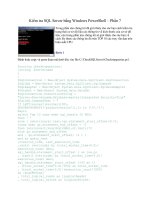
Tutorial 9: Mixing Tube
This is a simple example which shows how to add extra surfaces to a model which can then be used for boundary
conditions. The picture above shows the geometry: the three circular holes will be used in the final CFD simulation
to inject the reactants to be mixed, and they must exist as distinct surfaces to allow the inlet boundary conditions
to be defined in the simulation. The following geometry and meshing features are illustrated:
• Imprint Surfaces, to add surfaces for boundary conditions;
• curvature-sensitive meshing;
• Inflation;
• Stretch, to reduce the number of elements along one axis; and
• Preview Groups, to view part of the surface mesh.
If you want to skip the geometry creation part of the tutorial, then see the instructions in Introduction to the
CFX-Mesh Tutorials.
1. Geometry Creation
Creating the Project
1.
Open ANSYS Workbench, and create a new empty project. Save it as Reactor.wbdb.
2.
Choose New Geometry open DesignModeler, specifying the units as millimeters.
Creating the Solid
The first step is to create the solid for the mixing tube.
1.
Create a new sketch (
) based on the XYPlane.
CFX-Mesh Tutorials . . © SAS IP, Inc.
2.
Use Rectangle from the Draw Toolbox of the Sketching tab to create a rectangle which extends from 0
< X < 60 mm and -10 mm < Y < -4 mm.
3.
Select
Revolve from the 3D Features Toolbar.
4. Set the axis for the rotation as follows. First, click on the line which forms the bottom of the rectangle (Y
= -10 mm), and then click on Apply in the Details View.
5.
Set Direction to Both - Symmetric and Angle to 15 degrees.
6.
Click on
Generate to create the solid.
Notice that the curved surface of the solid consists of just one surface, as can be seen by clicking on it.
Breaking up the Curved Surface
You need to break up this surface so that the three circular holes are created as separate surfaces. The basic
method to do this is to create a sketch containing the three circles, and then to Extrude with Imprint Surfaces to
effectively project the circles onto the full curved surface.
1.
Create a new sketch ( ) based on the ZXPlane.
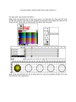
2.
Use Circle from the Draw Toolbox of the Sketching tab to create three circles in this sketch, as shown
below. The circles each have radius 0.75 mm, and their centers are positioned 5 mm, 15 mm and 25 mm
from the X-axis respectively. The easiest way to do this is to draw the circles in approximately the right
position. Then use Equal Radius from the Constraints Toolbox of the Sketching tab to set two of the
circles to have the same radius. Repeat to set the third circle to have the same radius as one of the other
two. Then set the radius of any one of the circles to be 0.75 mm, and the other circles will automatically
take the same radius. You can then set their distances from the X-axis appropriately.
Note that if you happen to draw the circles sufficiently close to having an equal radius, then DesignModeler
will apply an Auto Constraint to the circles, constraining their radii to be equal. If this happens and you
try to set the radius of both circles explicitly, then you will see a warning: “New dimension makes model
over-constrained.” when you try to dimension the radius of the second or subsequent circle. If you do
see this warning, then click OK to clear the warning and then right-click over the Model View and select
Cancel. You will not need to set a dimension on this circle in this case: its radius will always be identical
to the radius that you have already set.
Tutorial 9: Mixing Tube
CFX-Mesh Tutorials . . © SAS IP, Inc.
88
Now you can create the Extrude.
1.
Select Extrude from the 3D Features Toolbar.
2.
Set Base Object to be the new sketch (Sketch2), and set Operation to Imprint Faces.
3.
Set Direction to Reversed, Type to be To Faces, and select the curved surface as the Target Face.
4.
Click on
Generate to break up the surface.
You should now find that if you click on the curved surface of the solid, it consists of four separate surfaces: the
three circles and the remainder.
The geometry is now complete.
1.
Select File>Save to save the geometry file.
2. Mesh Generation
First open CFX-Mesh.
1. Switch from DesignModeler to the Project Page using the tabs at the top of the window, and click on
Generate CFX Mesh to open CFX-Mesh.
Setting up the Regions
Create the 2D Regions:
1.
Create a Composite 2D Region called InWater on the nearly-triangular face with the lowest X-coordinate.
2.
Create a Composite 2D Region called InAcid on the circular face nearest to the InWater 2D Region which
you have just created. The circle is part of the curved face of the reactor.
3.
Create a Composite 2D Region called InAlkali on the two remaining circular faces.
89
CFX-Mesh Tutorials . . © SAS IP, Inc.
Section 2: Mesh Generation
4.
Create a Composite 2D Region called out on the nearly-triangular face with the highest X-coordinate.
5.
Create a Composite 2D Region called sym1 on the planar face with the higher Z-coordinates.
6.
Create a Composite 2D Region called sym2 on the planar face with the lower Z-coordinates.
Setting up the Mesh
Set the Maximum Spacing:
1.
Click on Default Body Spacing in the Tree View, which is contained in Mesh>Spacing.
2.
In the Details View, change Maximum Spacing to 0.6 mm, and press Enter on the keyboard to set this
value.
A fine mesh is required around the circular inlets. In this tutorial, you will use curvature-sensitive meshing. Using
this utility, the mesh will automatically be refined in regions where the edges of the surfaces have a large curvature.
1.
Click on Default Face Spacing in the Tree View, which is contained in Mesh>Spacing. This is a Face
Spacing object which is applied to all faces which do not have a Face Spacing explicitly defined.
2.
Set the Angular Resolution to 18 degrees. The mesh will be refined wherever two adjacent surface
mesh edges make an angle of more than the number of degrees set by the Angular Resolution setting.
3.
Set Minimum Edge Length to 0.15 mm. This prevents over-refinement in areas which have a very large
curvature.
4.
Set Maximum Edge Length to 0.6 mm and leave the other parameters to the default settings.
Generating the Surface Mesh
To see the effects of curvature-sensitive meshing, preview the surface mesh on the wall of the reactor.
1.
Right-click over Preview in the Tree View, and select Insert>Preview Group. Change the name of the
Preview Group to wall.
2.
For Location, select the Composite 2D Region Default 2D Region from the Tree View.
3.
Now right-click over the Preview Group wall in the Tree View, and select Generate This Surface Mesh.
The surface mesh will be generated on just the corresponding faces.
4. Zoom into the area around the three circular inlets by clicking with the right mouse button and dragging
a zoom box over the area required.
You will see that the mesh has been automatically refined around the three inlets.
Setting up Stretch and Inflation
Since the geometry is long and thin, it is appropriate to generate a stretched mesh to expand the mesh elements
in the X-direction. In practice, the geometry is expanded by the specified factors, meshing takes place and then
the geometry is contracted back to its original size. This results in fewer elements along the length of the reactor
without affecting how many elements are present in a cross-section of the tube.
Tutorial 9: Mixing Tube
CFX-Mesh Tutorials . . © SAS IP, Inc.
90
1.
Click on Stretch in the Tree View.
2.
Set Stretch in X to 0.5 and leave the other stretch factors set to 1.
3.
Regenerate the mesh by right-clicking on the Preview Group wall and selecting Generate This Surface
Mesh.
It is a good idea to put inflation on the reactor wall.
1.
Click on Inflation in the Tree View. In the Details View, set Number of Inflated Layers to 5.
2.
Set Expansion Factor to 1.3. Leave the rest of the parameters as their default values.
3.
In the Tree View, right-click on Inflation and select Insert>Inflated Boundary.
4.
For Location, select Default 2D Region from the Tree View.
5.
Set Maximum Thickness to 0.6 mm.
Generating the Volume Mesh
Finally, you can generate the volume mesh.
1.
Right-click on Mesh in the Tree View and select Generate Volume Mesh.
2.
Save the GTM File as ReactorMesh.gtm.
The mesh is now complete.
1.
Select File>Save to save the CFX-Mesh database.
2.
Switch to the Project Page using the tabs at the top of the window, and choose File>Save to save the
project.
If you want to continue by working through the CFX-5 example “Tutorial 13: Reacting Flow in a Mixing Tube”
using the newly-generated mesh, and have CFX-5.7.1 in ANSYS Workbench installed on your machine, then follow
these steps:
1.
On the Project Page, a new entry will have appeared when you generated the file: Advanced CFD. Under
this entry, double-click on ReactorMesh.gtm to open up CFX-Pre.
2.
Once CFX-Pre has opened, choose File>Save Simulation As to save the simulation as Reactor.
3. Work through the CFX-5.7.1 tutorial, missing out the instructions in the sections “Creating a New Simu-
lation” and “Importing a Mesh”.
If you do not have CFX-5.7.1 in ANSYS Workbench installed or do not want to work through the CFX-5 example,
then:
1.
Exit from ANSYS Workbench by selecting File>Exit.
91
CFX-Mesh Tutorials . . © SAS IP, Inc.
Section 2: Mesh Generation
92
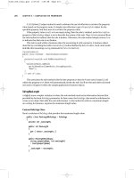
Tutorial 10: Heating Coil
This example creates the geometry and mesh for a heating coil, which consists of a solid copper coil in a vessel
containing liquid. Two solid bodies are required, one for the coil and one for the containing vessel. The following
geometry and meshing features are illustrated:
• the Sweep operation to create the coil;
• multiple solid bodies;
• Body Operations;
• Face Spacing, to refine the mesh on a particular face;
• Inflation;
• Proximity; and
• Preview Groups, to view part of the surface mesh.
If you want to skip the geometry creation part of the tutorial, then see the instructions in Introduction to the
CFX-Mesh Tutorials.
1. Geometry Creation
Creating the Project
1.
Open ANSYS Workbench, and create a new empty project. Save it as HeatingCoil.wbdb.
2.
Choose New Geometry to open DesignModeler, specifying the units as meters.
CFX-Mesh Tutorials . . © SAS IP, Inc.
Creating the Profile and Path
You will use the Sweep action to create the coil, and this requires sketches to define the profile (the circle which
forms the cross-section for the coil) and the path around which it will be swept.
1.
Create a new sketch ( ) based on the YZPlane.
2. The sketch needs to contain a circle with radius 0.1 m and centered on Y = 0.75 m, Z = 0.5 m. Set up the
grid to have a Major Grid Spacing of 1 m and Minor-Steps per Major of 4 to help you position the
center of the circle.
3.
Use Circle from the Draw Toolbox of the Sketching tab to create the circle centered on Y = 0.75 m, Z =
0.5 m with any convenient radius. Then adjust the radius to 0.1 m by using the Dimensions section of
the Sketching tab.
4. This example will split the circle into two pieces, for reasons which will be explained later on. To break
the circle into two pieces, use the Modify Toolbox of the Sketching tab. Click on Split, then right-click
on the Model View and select Split Edge into n Equal Segments.
5.
Back on the Sketching tab, next to where you clicked on Split, you will now find a box which allows you
to specify how many segments to break the circle into. Set it to 2 and select the circle in the Model View
to perform the Split operation.
6.
Create another new sketch (
), Sketch2, also based on the YZPlane.
7.
Use the Line tool from the Sketching tab to create a single straight line along the Z-axis, from Z = 0.5 m
to Z = 1.5 m.
Using Sweep to Make the Coil
1.
Select
Sweep from the 3D Features Toolbar.
2.
Set the Profile to be Sketch1: click on Sketch1 in the Tree View and then click on Apply in the Details
View at the bottom-left of the screen.
3.
Set the Path to Sketch2: click on the Not selected text next to Path, click on Sketch2 in the Tree View,
and then click on Apply.
4.
Set the Scale to 1.
5.
Set the number of Turns to 2.
6.
Click on
Generate to create the coil.
Tutorial 10: Heating Coil
CFX-Mesh Tutorials . . © SAS IP, Inc.
94
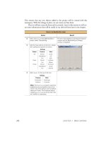
Extruding the Bottom End of the Coil
If you look at the full picture of the geometry at the top of this example, you will be able to see that the ends of
the coil are extruded to the edges of the container. However, the extrusion is not normal to the faces at the end
of the coil: if you were to extrude in the normal direction then the coil would look like the picture (a) below,
whereas the actual coil is shown in picture (b).
(b)(a)
To create the extrusion in a direction which is not normal to the faces, you need to define a vector which gives
the direction for the extrude. The way that you will create the vector here is to calculate explicitly the angle
at which the extrusion takes place to maintain the smooth gradient from the main coil into the extrusion.
Straightforward trigonometry shows that the angle between the path and the horizontal is 6.06 degrees:
95
CFX-Mesh Tutorials . . © SAS IP, Inc.
Section 1: Geometry Creation