Introduction to Character Animation phần 6 potx
Bạn đang xem bản rút gọn của tài liệu. Xem và tải ngay bản đầy đủ của tài liệu tại đây (395.91 KB, 18 trang )
With the tip still selected, do a constrained extrude along the Z axis with E,Z to
make the second bone in the chain (Extruding the spine 1).
Do three more Z-constrained extrudes so you have a total of 5 spine bones
(Extruded spine). The rib cage doesn't bend in a human, so this spine is a little
more flexible than it would be in a real human.
Extruding the spine 1.
Extruded spine.
Extrude a neck and a head bone. Note the head bone
extends out the top of the head a little bit. That's so
we can easily select the bone even if X-Ray is turned
off for the armature.
We should name these bones. The names will appear in other parts of the interface, so it's useful to give them meaningful
names now to avoid confusion later.
With a bone selected, you can change the name of the bone in the
Edit buttons Armature Bones panel (Armature Bones panel in the
Edit buttons). I selected the bottom bone and changed the name to
spine1.
Select the each of
the other bones in
the spine and name
them something
meaningful. I
named them, from
the bottom, spine1,
spine2, spine3,
spine4, spine5,
neck, and head.
When they are all
selected, they all
show up in the Edit
buttons (Named
spine bones).
Extruding the arms symmetrically
Neck bone.
Head bone.
Armature Bones panel in the Edit Buttons.
Named spine bones.
Go back to Front View ( NumPad 1)
Select the tip of spine4.
Something new: Shift E to symmetrical extrude and create a
shoulder bone, as in Symmetrically extrude the shoulder bones.
Symmetrical extrude only works if we have X-Axis Mirror Edit
mode on, which we (conveniently enough!) turned on a couple
steps back.
With the tip of the shoulder still selected, do another Shift E
symmetrical extrude to make an upper arm bone (Symmetrically
extrude the upper arm bones).
Continue symmetrically extruding to make the lower arm . . .
. . .the hand bone . . .
. . .and two fingers
bones.
We have all the arm bones, now lets position them a little better. It's easiest to do this if we can see roughly where the
vertices are in the mesh. Since we're working in the Armature's Edit mode, we can't view vertices in the mesh's Edit mode
Symmetricaly extrude the shoulder bones with
Shift E.
Symmetrically extrude the upper arm bones.
Symmetrically extrude the lower arm bones.
Symmetrically extrude the hand bones.
Symmetrically extrude the finger bones (1).
Symmetrically extrude the finger bones (2).
as well. Instead,
TAB to exit the armature's edit mode.
Select the character mesh.
Turn off "Subsurf in interactive view" in the Subsurf modifer. This
will allow us to see the true base mesh, and line up the bones
accordingly (try Wireframe mode without doing this step to see
what I mean).
Switch to Wireframe view with Z.
Select the armature again, and enter Edit Mode ( TAB ).
Adjust the elbow so that it falls within the three elbow vertices in
the mesh (Adjusting the elbow from Front View)
Do the same from Top View (Adjusting the elbow from Top View).
Disable Subsurf in the 3D Window.
Adjusting the elbow, from Front View.
Adjusting the elbow from Top View.
While you're in Top View, make sure all the arm bones fall within
the mesh (Top view of arm bones).
TAB , select character mesh, turn Subsurf back on in interactive
view, hit
Z again for shaded mode
Select the armature again and enter Edit Mode.
Naming the bones
N
ow for some naming. We have to be careful about naming these bones.
Bone naming conventions
In order to have some very handy X-Axis mirror tools work, we need to name symmetrical bones something like "bone.L"
for the left bone, and "bone.R" for the equivalent right bone.
You could also use "bone.l" and "bone.r", or "Left.Bone" and "Right.Bone" . . . the symmetrical tools are pretty smart that
way ONLY as long as both symmetrical bones have the same naming convention.
To be consistent, I'm going to use:
All lowercase letters for the bone names, including "l" and "r" for left and right
Two-word bones will have an underscore separating the names (upper_arm.l)
The LEFT side is the CHARACTER'S left side. In front view, this often means you have to think a second before
deciding which is left or right.
Change the names of the bones to something that makes sense. Just make sure that the left and right bones are
symmetrical. Under the Edit buttons (same place you turned on X-Ray and X-Axis Mirror Edit), you can turn on
Draw Names. This will display the names of the bones, and is helpful to see if you missed naming any bones.
B
one names, below, is a screenshot of the names of the bones I used. You'll probably have to click on the image to view it
full size and see the bone names. It's at a strange angle so that all bone names are clearly visible. The names I used were:
Top view of arm bones.
shoulder.l
upper_arm.l
lower_arm.l
hand.l
finger1.l
finger2.l
and
shoulder.r
upper_arm.r
lower_arm.r
hand.r
finger1.r
finger2.r
Testing the rig and adjusting the arms for Auto-IK
By now, you're familiar with Object mode and Edit mode. We're going to use another mode that's specific to armatures:
Pose mode.
With the armature selected, press
Ctrl TAB . This essentially substitutes Object Mode for Pose Mode. In other
words, you can now press
TAB and switch between Pose mode and Edit Mode. If you need to get Object mode
back, press
Ctrl TAB again, and you can then switch between Object and Edit mode with TAB . You know you
are in Pose mode when you select a bone and it is outlined in light blue.
For armatures, Edit mode is used to construct the armature. Object mode is to move the entire armature as a whole. Pose
mode is used for, well, posing. In Pose mode, you can grab, rotate, and scale each bone individually.
Bone names, upper body
upper_arm.l selected in Edit mode.
upper_arm.l selected in Pose mode.
Armature selected in Object mode
(individual bones cannot be selected
in Object mode).
Try selecting the upper arm in Pose mode and rotating it in Front
view. Notice how all bones "downstream" of it rotate as well.
Now select the lower arm and rotate it in Front view. The upper
arm stayed in place, but the lower arm and everything
"downstream" rotated. This is the essence of parenting.
That is, the upper arm is the parent of the lower arm. The lower arm is in
turn the parent of the hand bone. Another way to say that is that the hand
is the child of the lower arm. These parent-child relationships were
automatically created when we extruded the bones. The extruded bone
becomes the child of whatever it was extruded from. That's the reason we
started from the lower spine and extruded upward, as well as starting at
the shoulder and extruding toward the fingers.
Clear the rotation of all bones by
using
A twice to select all, then
Alt R to clear rotation. The bones
are now reset to their original
rotations. You'll end up using this
command a lot, along with the
related command
Alt G , which
clears location.
Turn on Auto IK in the Armature panel, under the Edit
buttons.
upper_arm.l rotated in Front view.
lower_arm.l rotated.
Clearing the rotation of all
bones in the armature.
Turn on Auto IK in the Armature panel.
Select the tip of the arm and move it with G . Note that it moves
much differently now!
A little explanation: Forward Kinematics, or FK, is the way of moving bones that we first used. That is, rotate the upper
arm, and its children (and children's children!) follow along. The opposite of FK is Inverse Kinematics (IK), where we
move a child and the parents follow along. In reality, there is some fancy math going on in the background that tries to
p
oint the chain of bones toward the target. What's the target? For Auto-IK, it's whatever bone you have selected. In this
case, the target is the finger2.l bone. What's the chain? It's the lineage of bones going all the way back to the
great-great-great-(etc)-grandparent.
In our armature, when we moved the finger bone, all the bones in the chain tried to point to wherever we moved it. An
orange line showed up, connecting the finger2.l bone to the spine1 bone. The orange line points to the root of the chain:
spine1 is the highest parent of finger2.l, and the chain is everything between spine1 and finger2.l.
It would be nice if the spine didn't move so much when we moved the arm. We'll fix this by essentially breaking the IK
chain at the shoulder so only the arm moves and the spine stays still.
Go into Edit mode of the armature with
TAB . Note that even
though you may have just moved some bones around in Pose mode,
upon entering Edit Mode everything goes back to the way it was. In
Edit Mode, you're viewing the bones as they are in Rest position,
and once you go back out to Pose mode, your posed armature will
return.
Select the upper_arm.l bone in Edit mode.
finger2.l moved with Auto IK.
Select upper_arm.l in Edit mode.
In the Armature Bones panel under the Edit buttons,
deselect the Con button. In this panel, the child of:
menu indicates that this bone, upper_arm.l, is the child
of shoulder.l. We want to keep that relationship, but
we'd like to allow upper_arm.l to be disconnected
from shoulder.l . . . and therefore break the IK chain.
Con stands for Connected. By deselecting this button,
we disconnected the upper_arm.l bone from the
shoulder.l bone.
To test this new setting, switch to Pose mode ( TAB ).
Reset the armature by pressing A twice to select all bones,
Alt G to clear locations, and Alt R to clear rotations.
Now, move the finger2.l bone again. Much different! The orange
line now points to the root of the chain, which is the upper_arm.l
bone.
While we were able to extrude bones symmetrically, we have to make changes to the settings separately. To disconnect
the upper_arm.r bone from shoulder.r in the same way,:
Switch to the armature's Edit mode
Select upper_arm.r.
Deselect the Con button.
Test the armature.
Apply the Armature modifier to the Mesh
Deselect the "Con" button to disconnect upper_arm.l from
shoulder.l.
Moving the finger2.l bone after breaking the
IK chain at upper_arm.l.
N
ow that we have an
armature, it's time to
attach it to the mesh. To
do this, we'll add an
Armature Modifier to the
mesh.
Select the character
mesh, in Object
Mode
In the Edit Buttons,
choose
Add Modifier>>Armature
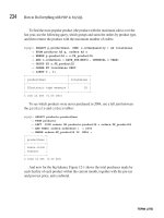
In the Ob: text box,
enter the name of
the armature object
(Enter the name of
the armature object
into the armature
modifier). The
default armature
name is, logically
enough,
"Armature". To
double check the
name of your
armature, select the
armature and look
for the OB: text box
in the Edit buttons,
like in Checking the
name of the
armature.
In the Armature Modifier, make sure only Vertex Groups buttons are selected. We will not be using Envelopes in
this tutorial.
N
ow Blender knows that we want the armature to affect the character mesh. Next, we need to tell Blender exactly what
vertices to move when we move, say, upper_arm.l.
Summary:
We added an armature object, and sequentially
extruded bones to make an armature for the upper body. We
made some changes to allow for the use of Auto-IK, should we
choose to use it later on. Next up: weight painting!
N
ext: Upper body: weight painting
Previous: Materials and textures
Back to Index
Retrieved from
" />Checking the name of the armature (select it
and check the name that shows up here).
Enter the name of the armature object into the
armature modifier, and make sure only Vertex
Groups is selected (Envelopes should be
unselected.
This page was last modified 08:36, 24 August 2006.
BSoD/Introduction to Character Animation/Upper body
weight painting
From BlenderWiki
< BSoD | Introduction to Character Animation
Contents
1 Weight Paint mode
2 Weight painting the upper arm
3 Tips for weight painting
4 Weight paint the rest of the arms
5 Weight painting the head and torso
6 Parenting the eyes to the head bone
7 Testing the rig
Weight Paint mode
We're going to tell Blender which vertices in the mesh to move whenever we move a bone in the armature. While we
could manually choose vertices and assign them to groups, a more powerful way to do this is with Weight Paint mode.
First, let's make the
bones a little less
obtrusive. Select the
armature.
In the Armature panel
under the Edit buttons,
choose Stick as the
draw type. This
changes the bones
from bulky
octahedrons (which are
a useful shape for
building armatures)
into thin sticks that
don't take up as much
space on the screen.
Change the armature draw type to Stick.
Armature in Stick draw type.
Note: In order to select bones in the armature while weight
painting, the armature has to be in Pose mode.
Make sure the armature is in Pose mode.
Select the character mesh.
Switch to the mesh's Weight Paint mode with Ctrl TAB . Similar to Pose mode for armatures, we've substituted
Weight Paint mode for Object mode.
N
otice the mesh turns dark blue. As you'll see, weight painting uses colors to represent information about groups of
vertices.
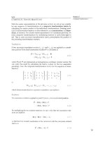
In the Edit buttons a new panel is now available: the Paint
panel. Make the following settings:
Change Weight to 1.0. This determines the color of
the brush.
Change Opacity to 1.0. This is how much "paint" is
applied with each brush stroke.
Turn off All Faces. This gives us a little more control
over what gets painted.
Turn off Vertex Dist. This will also give us more
control.
Leave Soft on, but this is mostly personal preference.
For what we're doing, it just makes the painting look
a little smoother.
Important: Turn X-Mirror on. This will let us take
advantage of our symmetrically-named bones, so
we'll only have to paint one side!
The Weight in weight painting refers to the strength of a bone's influence. With the upper_arm.l bone selected, we want
the vertices in the upper arm of the mesh to be influenced. So we paint them!
Character mesh, in Object mode.
Character mesh, in Weight Paint mode.
The Paint panel.
Weight painting the upper arm
Select the upper_arm.l bone with RMB . Even though we're in
the mesh's weight paint mode, we can still select bones because we
told the mesh we're going to be using this armature using the
Armature modifier.
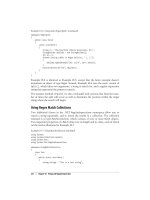
Using LMB , carefully paint over the the upper_arm.l bone with
the brush. The mesh now appears red, indicating those vertices
have a weight of 1.0 when it comes to being affected by
upper_arm.l. Other colors indicate other weights, but for the
purposes of this tutorial we will use all weights of 1.0.
Rotate the view to get a good look at the back of the mesh.
Ctrl NumPad 1 is a quick way to do this (Rear view). Paint the
back side of upper_arm.l as well.
upper_arm.l selected while in the mesh's
Weight paint mode.
Weight painting vertices for upper_arm.l, from
Front view.
Weight painting vertices for upper_arm.l, from
Rear view.
Select the upper_arm.l bone and rotate it ( r ). The mesh deforms
along with the bone.
Select upper_arm.r on the other side. Notice the vertices for this
bone are already painted! That's because we named the bones
symmetrically (l and r) and enabled X-Mirror in the Paint panel.
Blender found the bone on the other side and mirrored the weights
for us.
Select upper_arm.l again and clear its rotation with Alt r.
Tips for weight painting
Here are some tips to keep in mind while weight painting.
The vertices you paint will be assigned to the bone you have selected.
Make sure you paint over only the vertices you want to move with the bone you have selected. A little bit bleeding
over into an adjacent bone's area may be OK.
If you make a mistake, Ctrl Z only undoes the last step, not multiple steps. I find that the best way is to press the
Clear button in the Paint panel. This clears all weights for the selected bone. Important: Clearing the weights does
NOT happen symmetrically! If you aren't happy with upper_arm.l and clear it to start over on that bone, you have
to select upper_arm.r and clear the weights on that bone as well. Otherwise you'll end up with residual weights on
upper_arm.r that will make things unsymmetrical.
It doesn't matter if your weights don't look exactly like those pictured here, as long as you're happy with the
resulting deformation of the mesh when you move the bones around.
Weight paint the rest of the arms
Rotating upper_arm.l: the mesh move along.
upper_arm.l selected.
Select lower_arm.l and weight paint it. Don't forget to rotate around to the other side of the mesh to paint the back
of the lower arm as well.
Continue on down to the hand and finger bones, first selecting the bone and then weight painting from the front and
back.
If you make a mistake: If you make a mistake while weight
painting,
Ctrl z only undoes one step. The most
straightforward way to fix a mistake is to reset the weights for
the bone you have selected by pressing Clear in the Paint panel,
and redo the weights for that bone.
Weights for lower_arm.l.
Weights for hand.l.
Weights for finger1.l.
Weights for finger2.l.
Now select the finger2 bones and move them. If Auto-IK is
enabled, the arms should move along with them. Auto-IK is a
property of the armature, so if it's not enabled, you have to switch
to Object mode, select the armature, and turn on Auto-IK.
Sometimes you'll miss painting a vertex at all. When you go to move the
bones, you might see something like this:
To correct it, select the bone that should move those vertices . . .
The arms now move!.
Arm isn't deforming correctly.
Select the bone . . .
and then paint the uncooperative vertices. They should snap back into
p
lace where they should be.
Depending on how you modeled your character, it may take some playing around with in Weight Paint mode to get the
bones to deform the character correctly.
To reset the bone rotation and location, we have to exit out of Weight Paint mode with
Ctrl TAB
Then select the armature.
Use the A-A-Alt G-Alt R combination to clear the location and rotation of all bones.
Re-select the character mesh.
Switch back to Weight Paint mode ( Ctrl TAB , with the armature reset to rest position.
Weight painting the head and torso
N
ow let's weight paint the head and torso.
Switch to Weight Paint mode for the character mesh.
Select the head bone.
Paint away! Don't forget the front and back.
With the head bone still selected, move it backward in Side view
with
g . Whoa! What's going on?
By moving the head, we're able to see that we missed some
vertices. It turns out that these are the vertices on the inside of the
head that we couldn't see before: the inner faces of the eye sockets,
and the inside of the mouth.
And paint the offending vertices.
Moving the head bone back.