Communication Systems for the Mobile Information Society phần 8 ppsx
Bạn đang xem bản rút gọn của tài liệu. Xem và tải ngay bản đầy đủ của tài liệu tại đây (403.68 KB, 39 trang )
Wireless Local Area Network (WLAN) 245
Internet is also available where no UTMS coverage yet exists and also ensures connectivity
when traveling abroad (international roaming).
As the UMTS core network is an evolution of the already existing GSM and GPRS
networks, a functioning world-wide billing solution already exists. WLAN on the other hand
does not have a standardized billing solution. This is due to the fact that for many scenarios
like for home and office use, for which the WLAN standard was initially conceived, no billing
was necessary. For commercial hotspots, like in hotels, however, billing is an essential task.
Due to missing standards and the vast number of hotspot operators, a number of different
billing methods are appearing on the market. These range from scratch cards that can be
bought at the hotel’s reception desk, online credit card payment, and billing via the GSM
or UMTS. The later billing method can only be used if the WLAN hotspot is operated by
the mobile operator of the user. In most cases, a user is therefore not able to use the hotspot
right away but has to deal with billing first.
An open issue for public use of WLAN is the technical realization of lawful interception
by the authorities. This contrasts other telecommunication networks including GSM, GPRS,
and UMTS, for which most countries have passed laws and standardized methods to allow
access by police and other organizations to the data that a user transfers. This process has
not yet started for WLAN hotspots and is also not easily achievable due to the current user
authentication architecture. With the increasing success of WLANs it is likely that laws will
be put into place for this technology as well. This will force many WLAN hotspot operators
to redesign their current user authentication and data routing functionality.
WLAN has been designed for small coverage areas. This area can be somewhat increased
by using several access points to form an ESS. As all access points have to be in the same
IP subnet (see Section 4.4 and Figure 4.9), the maximum coverage area is still limited to
the size of a single building. For most WLAN applications, this limitation is acceptable,
especially because automatic access point changes are possible. UMTS on the other hand has
been designed for nationwide coverage. Furthermore, the standard has been designed (see
Chapter 3) for seamless handovers between cells to maintain connections over long periods
and distances as well as at high speeds of up to 500 km/h. Only these methods enable users
to make calls while being on the move or to connect their PDAs or notebooks to the Internet
while traveling in trains or cars.
The size of cells also differs greatly between WLAN and UMTS. WLAN is limited to a
few hundred meters due to its maximum transmission power of 0.1 Watt. Inside buildings,
the range is further reduced due to obstacles like walls. UTMS cells in practice can stretch for
several kilometers but can also be used to cover only certain buildings or floors (pico-cells),
for example shopping centers, etc.
Strong security and encryption were only added to the WLAN standards once the system
was already popular. While WPA and WPA2 (802.1x) offer good security and privacy for
private and company networks, security is still a problem for public hotspots. Especially in
this market, WPA will most likely not be introduced, as keys would have to be manually
configured by the user.
As all users of a hotspot get an IP address in the same subnet, a user should ensure that his
notebook is protected against hacker attacks from the same subnet. An adequately configured
firewall and an up-to-date virus scanner on a client device is an absolute must. Some access
points offer to protect users by preventing direct communication between devices of the
hotspot. The ‘client isolation’ feature is based on layer 2 MAC filtering. In practice, however,
246 Communication Systems for the Mobile Information Society
there is no guarantee that such a feature has been implemented or activated in an access
point. UMTS devices can also be accessed by other devices in the network. Different users
in the same area, however, do not usually belong to the same subnet. A UMTS user has no
means of finding out which IP addresses have been given to devices in the local area thus
preventing him from launching a specific attack. As security is part of the overall design
of UMTS, a user does not have to take care if and how the connection to the network is
encrypted as the system automatically encrypts the link to the user. The user also does not
have to worry about key management, as the key for authentication and ciphering is stored
on the SIM card.
Telephony is another important application. The circuit-switched part of the UMTS
network has been specifically designed for voice and video telephony. These two services
are not covered by WLAN hotspots today. However, a clear trend can be seen towards voice
(and video) over IP (VoIP). UMTS addresses this with its IMS architecture (see Chapter 3).
Wireless hotspots benefit from this trend as well. Various VoIP software clients, together
with a notebook, enable the user to make calls via WLAN at home, in the office, or at
a public hotspot. Recently, devices like the Nokia Communicator have introduced WLAN
connectivity in addition to GSM and UMTS access. To ensure a good quality of service
for telephony applications in heavily loaded hotspots, an extension to the DCF of access
points is required (see Section 4.5) to ensure a constant bandwidth and latency for the call.
A solution for this problem has already been standardized in the 802.11e specification, but
it will still take a number of years before these features are available in public hotspots and
client devices. It also should be noted that the majority of public hotspots are connected to
the Internet via DSL lines with limited uplink bandwidths of only a few hundred kilobits
per second. This limits the number of simultaneous voice calls to two or three. Due to these
reasons, telephony over public WLAN hotspots will only complement the current voice-call
capabilities of GSM and UMTS networks. To standardize VoIP using public hotspots, the
3GPP community has worked on an extension of the UMTS standard in the technical speci-
fications TS 22.234 [4], 23.234 [5] and 24.234 [6]. These Release 6 standards describe how
the UMTS IP multimedia subsystem (IMS) can be extended to public WLANs.
In summary, WLAN is a hotspot technology that offers fast Internet access to users in a
small area for a limited amount of time. Due to the simplicity of the technology compared
to UMTS, as well as the use of license-free bands, costs for installation and operation of
WLAN hot spots are lower than for a UMTS cell. Together with a fast backhaul connection
to the Internet, WLAN can offer fast data transmission capabilities for private, office, and
public use. In practice, WLAN is the standard connection technology for notebooks and
PDAs today. WLAN reaches its technical limits in cars or trains and due to its maximum
coverage area, which is typically the size of a building. Due to these limitations, the term
‘nomadic Internet’ is sometimes used for WLAN Internet access. Users typically move into
the coverage area of a cell for some time during which they will be mostly stationary, before
leaving the area again.
UMTS, on the other hand, addresses the needs of mobile users that need to communicate
while being on the move. With its fast data transfer rates, UMTS is also ideally suited for
accessing the Internet if no WLAN hotspot is available that can be used at a lower price. The
complex technology, compared to WLAN, is necessary to support the mobility of users and
for applications like telephony at any place any time. This makes UMTS more expensive
than WLAN. The huge frequency licensing fees that mobile operators have paid in many
Wireless Local Area Network (WLAN) 247
countries are also adding a significant amount to the total cost. The main applications for
UMTS are therefore mobile voice and video telephony, Internet access if no WLAN hotspot
is available, as well as WAP, MMS, video streaming, and instant messaging. Thus, UMTS
is considered as the ‘mobile Internet’, as the technology enables users to communicate at
any place, any time, even in cars and in trains.
4.9 Questions
1. What are the differences between the ‘ad-hoc’ and ‘BSS’ modes of a WLAN?
2. Which additional functionalities can often be found in WLAN access points?
3. What is an extended service set (ESS)?
4. What is an SSID and in which frames is it used?
5. What kinds of power-saving mechanisms exist in the WLAN standard?
6. Why are acknowledgment frames used in a WLAN?
7. Why do 802.11g networks use the RTS/CTS mechanism?
8. Why are three MAC addresses required in BSS frames?
9. How can a receiving device detect at what speed the payload part of a frame was sent?
10. What is the maximum transfer rate that can be reached in a data transfer between two
802.11g devices in a BSS?
11. Which disadvantages does the DCF method have for telephony and video streaming
applications?
12. Which security holes exist in the wired equivalent privacy (WEP) procedures and how
are they solved by WPA and WPA2 (802.1x)?
Answers to these questions can be found on the companion website for this book at
.
References
[1] IEEE, ‘Part 11: Wireless LAN Medium Access Control (MAC) and Physical Layer (PHY) Specifications’,
ANSI/IEEE Std 802.11, 1999 Edition (R2003).
[2] IEEE, ‘Part 3: Carrier sense multiple access with collision detection (CSMA/CD) access method and physical
layer specifications’, ANSI/IEEE Std 802.3, March 2002 Edition.
[3] R. Droms, ‘RFC 2131 – Dynamic Host Configuration Protocol’, RFC 2131, March 1997.
[4] 3GPP, ‘Wireless Local Area Network (WLAN) Interworking’, TS 22.234, V6.2.0, September 2004.
[5] 3GPP, ‘3GPP System to Wireless Local Area Network (WLAN) Interworking: System Description’, TS
23.234, V6.3.0, December 2004.
[6] 3GPP, ‘3GPP System to Wireless Local Area Network (WLAN) Interworking: User Equipment (UE) to
Network Protocols; Stage 3’, V6.1.1, January 2005.
[7] IEEE, ‘Part 11: Wireless LAN Medium Access Control (MAC) and Physical Layer (PHY) Specifications:
High-Speed Physical Layer Extensions in the 2.4 GHz Band’, ANSI/IEEE Std 802.11b, 1999 Edition (R2003).
[8] IEEE, ‘Part 11: Wireless LAN Medium Access Control (MAC) and Physical Layer (PHY) Specifications –
Amendment 4: Further Higher Data Rate Extensions in the 2.4 GHz Band’, ANSI/IEEE Std 802.11g, 2003.
[9] IEEE, ‘Part 11: Wireless LAN Medium Access Control (MAC) and Physical Layer (PHY) Specifications –
High-Speed Physical Layer Extensions in the 5 GHz Band’, ANSI/IEEE Std 802.11a, 1999.
[10] IEEE, ‘Part 11: Wireless LAN Medium Access Control (MAC) and Physical Layer (PHY) Specifications –
Amendment: Medium Access Control (MAC) Quality of Service Enhancements’, IEEE Std P802.11e/D13,
January 2005.
248 Communication Systems for the Mobile Information Society
[11] IEEE, ‘IEEE Trial-Use Recommended Practice for Multi-Vendor Access Point Interoperability via an
Inter-Access Point Protocol Across Distribution Systems Supporting IEEE 802.11 Operation’, IEEE Std
802.11F, 2003.
[12] IEEE, ‘Part 11: Wireless LAN Medium Access Control (MAC) and Physical Layer (PHY) Specifications –
Amendment 5: Spectrum and Transmit Power Management Extensions in the 5 GHz Band in Europe’, IEEE
Std 820.11h, 2003.
[13] IEEE, ‘Part 11: Wireless LAN Medium Access Control (MAC) and Physical Layer (PHY)
Specifications – Amendment 6: Medium Access Control (MAC) Security Enhancements’, IEEE
Std 802.11i, 2004.
5
802.16 and WiMAX
In recent years, advances in signal-processing technologies and increased processor speeds
have allowed wireless networks to evolve into broadband Internet access technologies. The
GSM system was first enhanced by the UMTS radio access network and later with the
high speed downlink packet access (HSDPA) standard, which allowed for wireless Internet
access at speeds of several megabits per second. CDMA systems have undergone a similar
evolution. Several large companies, like Intel for example, which thus far have had no major
market share in equipment sales for wireless networks have reacted in support of a new
system standardization effort by the Institute of Electrical and Electronics Engineers (IEEE)
to create an alternative wireless broadband network. This effort culminated in the ratification
of the 802.16-2004 standard [1]. In the press, the 802.16 standard is often referred to as
WiMAX (worldwide interoperability for microwave access), though this is not technically
accurate as will be explained below.
The capability of WiMAX to deliver high-speed Internet access and telephone services
to subscribers enables new operators to compete in a number of different markets. In urban
areas already covered by DSL and high-speed wireless Internet access, WiMAX allows
new entrants in the telecommunication sector to compete with established fixed-line and
wireless operators. The increased competition can result in cheaper broadband Internet access
and telephony services for subscribers. In rural areas with limited access to DSL or cable
Internet, WiMAX networks can offer cost-effective Internet access and may also encourage
HSDPA or 1xEvDO operators to extend their networks into these areas. Developing countries
with limited infrastructure connecting subscribers to a central office are another potential
market for WiMAX. By connecting them wirelessly, WiMAX allows these markets to
bypass fixed-line Internet access technologies. This has already happened for mass-market
telephony services with the introduction of wireless GSM networks, which offer phone and
messaging services to millions of people in the developing world. Previously, this market
was underserved for reasons such as missing infrastructure and lack of competition, which
kept prices at unaffordable levels. The introduction of WiMAX also drives the evolution
of other high-speed wireless access technologies, as standards bodies like 3GPP or 3GPP2
have to enhance their systems to stay competitive.
This chapter aims to give a technical overview of the 802.16 standard and compares
the capabilities and design of the system to other technologies like HSDPA and wireless
Communication Systems for the Mobile Information Society Martin Sauter
© 2006 John Wiley & Sons, Ltd
250 Communication Systems for the Mobile Information Society
LAN (802.11). In this way, the differences and similarities between these systems become
apparent allowing us to put the marketing promises into perspective with the real capabilities
of the technology.
5.1 Overview
802.16 is part of the 802 local and metropolitan area standards series of the IEEE. Other
important network technologies in this series include the 802.3 fixed-line ‘Ethernet’ standard
and the 802.11 wireless LAN standard. While the fixed-line and wireless local area network
standards share concepts concerning how the network is managed and how packets are
transferred between the devices, 802.16 as a metropolitan area network standard has taken a
fundamentally different approach. There are important differences on layer 1 (physical layer,
PHY) and layer 2 (data link layer, MAC) of 802.16 compared to 802.11 wireless LAN. The
most important ones are:
•
An 802.16 network can be operated in several modes. In the point-to-point mode, 802.16
is used to build a bridge between two locations. A second mode, the point-to-multipoint
mode, is used to offer Internet access and telephony services to private customers and
businesses. As this is the main application for the technology in the years to come, this
chapter focuses mainly on this mode.
•
In 802.16 point-to-multipoint mode, access to the network by client devices, also referred
to as subscriber stations, is managed from a central authority. In 802.11 (WLAN) in
comparison, clients can access the network whenever they detect that the air interface is
not being used.
•
Subscriber stations do not receive individual frames. In the downlink direction (network
to subscriber station), data is embedded in much larger frames. During transmission of the
frame, the network can dynamically adjust modulation and coding for parts of the frame
to serve subscriber stations closer to the base station with higher data rates than those
available to subscriber stations with less favorable reception conditions. In the uplink
direction, the same concept is used and subscriber stations are assigned individual parts
of a frame in which they are allowed to send their data.
•
Most 802.11 WLAN networks today do not offer quality of service (QoS) mechanisms
for subscriber stations or single applications like voice over IP, which are very sensitive
to variations of bandwidth or delay. Most of the time, the available bandwidth of the
network and the low number of users per access point compensate for this. The 802.16
standard on the other hand defines in detail how to ensure QoS, as metropolitan networks
are usually engineered for high loads and many subscribers per cell.
As in any standardized technology, companies interested in the technology and its success
have set up an organization to promote the adoption of the technology in the market
and to ensure that devices of different manufacturers are compatible with each other.
Interoperability is often hard to achieve, as most standards offer many implementation
options and leave things open to interpretation. 802.16 is no exception. The WiMAX
forum () is the organization that aims to ensure interoperability
between 802.16 devices of different manufacturers. Apart from promoting the technology,
it has defined a number of profiles to ensure interoperability and has launched the WiMAX
802.16 and WiMAX 251
certification program [2]. Vendors interested in ensuring interoperability with products of
other vendors can certify their equipment in WiMAX test labs. Once certified, they can
officially claim to be WiMAX compliant, which is a basic requirement of most network
vendors. The WiMAX forum for 802.16 therefore fulfills the same tasks as the Wi-Fi alliance
() does for 802.11 wireless LAN. Due to this relationship, the remainder
of this chapter uses the terms 802.16 and WiMAX interchangeably.
The 802.16 standard uses the protocol layer model shown in Figure 5.1. This chapter
will look at the individual layers as follows: first, the physical layer is discussed with the
different options the standard offers for different usage scenarios. Then, the physical layer
frame structure for point-to-multipoint scenarios is discussed, as this operating mode will
be used by operators to offer high-speed Internet access and telephony to consumers and
businesses. By comparing the frame structure to the WLAN architecture described in the
previous chapter, it will become apparent how the 802.16 standard deals with the additional
requirements of a metropolitan area network (MAN).
Due to the many tasks fulfilled by the MAC layer, it has been split into three different
sublayers. The privacy sublayer, which is located above the physical layer, deals with the
encryption of user data which can be activated after a subscriber has been successfully
authenticated by the network. This procedure is described at the end of the chapter.
The MAC common part sublayer deals with the connection establishment of subscribers to
the network, and manages individual connections for their lifetime. Furthermore, this layer
is responsible for packing user data received from higher layers into packets that fit into the
physical layer frame structure.
Finally, the MAC convergence sublayer offers higher layer protocols a standardized inter-
face to deliver user data to layer 2. The 802.16 standard defines interfaces for three different
higher layer technologies. The ATM convergence sublayer is responsible for handling the
Figure 5.1 The 802.16 protocol stack
252 Communication Systems for the Mobile Information Society
exchange of ATM (asynchronous transfer mode) packets with higher layers. This is mainly
used to transparently transmit ATM connections via an 802.16 link. The applications for
sending ATM frames are point-to-point connections for backhauling large amounts of data,
like connecting a UMTS base station to the network. ATM will not be used for communi-
cation with the user. Therefore, this part of the standard is not discussed in further detail
in this chapter, as the chapter concentrates on point-to-multipoint applications for delivering
Internet access and telephony services to end users. For this purpose, the MAC convergence
sublayer offers an interface to directly exchange IP packets with higher layers. This makes
sense as the Internet protocol is the dominant layer 3 protocol today. Alternatively, higher
layer frames can be encapsulated into 802.3 Ethernet frames, as shown in Figure 5.1, before
being forwarded to the MAC convergence sublayer. This allows any layer 3 protocol to be
transported over an 802.16 protocol, as the header of an 802.3 Ethernet frame contains an
information element which informs the receiver of the protocol (e.g. IP) used on the layer
above.
5.2 Standards, Evolution, and Profiles
WiMAX comprises a number of standards documents. The 802.16 standard in general
addresses the physical layer (layer 1) and the data link layer (layer 2) of the network. In
its initial version, 802.16a, the standard only supported line-of-sight connections between
devices in the frequency range between 10 and 66 GHz. If WiMAX is operated in point-to-
multipoint mode for Internet access, most subscriber stations in cities and even rural areas
will not have a free line of sight (LOS) to a WiMAX base station (BS) due to obstructing
buildings or landscape. WiMAX was thus extended in the 802.16d standard for non-line of
sight (NLOS) operation for the frequency range between 2 and 11 GHz. A single base station
only uses a fraction of the frequency ranges given above. The system is very flexible and
typical bandwidths per base station are between 3.5 and 25 MHz. The bandwidth allocated
to a BS mainly depends on regulatory requirements and available spectrum, as there are
many other wireless systems used in the 2–11 GHz frequency range, like UMTS, 802.11
wireless LAN and Bluetooth. In 2004, 802.16a and 802.16d were combined to form the
IEEE 802.16-2004 standard, which thus includes network operation in both LOS and NLOS
environments.
The first version of the 802.16 standard only addresses non-moving or low mobility users.
Subscriber stations either use internal antennas or roof-mounted external antennas if further
away from the base station. The 802.16e standard adds mobility to the WiMAX system and
allows terminals to roam from base station to base station. The intent of this extension is
to compete with other wireless technologies like UMTS, CDMA and WLAN for moving
subscribers using devices like notebooks while away from home or the office.
As a first step to foster alternative network topologies, 802.16f adds improved multi-hop
functionality for meshed network architectures. It describes how stations can forward packets
to other stations so they can reach devices that are outside the radio coverage of a sender.
As shown in Table 5.1, the 802.16 standard covers a wide range of different applications
and scenarios. The standard defines a number of profiles that describe how the different
physical layers and options defined by the standard are to be used.
The two profiles intended for delivering Internet access to private subscribers and busi-
nesses with stationary devices are the wirelessMAN-OFDM (wireless metropolitan area
802.16 and WiMAX 253
Table 5.1 802.16 standards documents
Standards document Functionality
802.16a Initial standards document, 10-66 GHz LOS operation only
802.16d NLOS operation at 2–11 GHz
802.16e Adds mobility to 802.16
802.16f Introduces multi-hop functionality
802.16-2004 Umbrella document which combines the different subdocuments
network – orthogonal frequency division multiplex) and wirelessMAN-HUMAN (high-speed
unlicensed metropolitan area network) profiles. They describe how 802.16 can be used for
point-to-multipoint NLOS applications in frequency bands below 11 GHz. The first profile
is intended for use in licensed bands where the operator pays for the right to use a certain
frequency range. The second profile is intended for license free bands such as the ISM
(industrial, scientific, and medical) band, which is also used by various other technologies
such as WLAN and Bluetooth. Both profiles use orthogonal frequency division multiplexing
(OFDM) for data transmission. This modulation technique is also used in the 802.11g WLAN
standard (see Chapter 4), and uses several carriers to transmit data.
The 802.16e extension of the standard uses the wirelessMAN-OFDMA profile to address
the requirements of mobile subscribers. Many enhancements and additions have been made
to the original profile and radio network and core network designs have been specified by
the WiMAX forum network group.
For other applications the standard defines the following profiles, which will not be
covered in further detail in this chapter:
•
WirelessMAN-SC: use of a single carrier frequency for point-to-point operation on
licensed bands between 10 and 66 GHz. Mainly intended for high-capacity wireless back-
haul connections.
•
WirelessMAN-SCa: use of a single carrier frequency for operation in licensed bands below
11 GHz.
5.3 WiMAX PHYs for Point-to-Multipoint FDD or TDD Operation
To communicate with stationary subscribers in a point-to-multipoint network, the 802.16
standard describes two basic options in the mirelessMAN-OFDM/HUMAN profiles.
For license exempt bands, time division duplex (TDD) is used. This means that the uplink
and downlink direction between the base station and a subscriber use the same frequency
band. Uplink and downlink are time multiplexed in a similar way as described in Chapter 4
for WLAN systems. The advantage of using a single frequency band for both directions is a
flexible partitioning of the available bandwidth for the uplink and downlink directions. For
applications like web surfing, the amount of data sent from the network to the subscriber
is much higher than in the other direction. For such applications, more transmission time is
assigned in the downlink direction than in the uplink direction. Disadvantages of TDD are
that devices cannot send and receive simultaneously and that a device has to switch between
transmit and receive state. As some time is required to switch between transmitting and
254 Communication Systems for the Mobile Information Society
TDD Operating Mode FDD Operating Mode
Guard band
Downlin
k
Uplink
Receive Transmit
Transmission Gap
Channel
bandwidth,
e.g. 7 MHz
One frame consists
of an uplink and a
downlink subframe
One frame
H1
One frame contains data of/for several users
H 234
A subframe contains a header
and data of/for several users
1
234
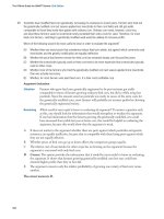
Figure 5.2 802.16 operation modes: TDD and FDD operation
receiving, some bandwidth is wasted during the required gap between the times allocated
for sending and times allocated for receiving.
Depending on national regulations, operators can also use licensed spectrum for their
network. This will be the rule rather then the exception, as the operation in license-free bands
is only allowed with minimal transmit power, usually well below 1 W. This power level
is usually not sufficient to cover large areas with a single base station, which is required
for economic operation of a network. In licensed bands, operators can choose between the
TDD mode described above and frequency division duplex (FDD) (see Figure 5.2). Here,
the uplink and downlink data flows use two frequency bands which are separated by a guard
band as in GSM, UMTS or CDMA. Full duplex devices can send and receive data at the
same time as in UMTS or CDMA. Subscriber stations, which are only half-duplex capable,
are only able to send or receive at a time. The 802.16 standard accommodates both types
of devices. Hence, subscriber stations have to announce their duplex capabilities during the
network entry procedure described further below.
5.3.1 Adaptive OFDM Modulation and Coding
The wirelessMAN-OFDM transmission convergence sublayer, which is part of the physical
layer, uses OFDM in both FDD and TDD mode in a similar way as wireless LAN, which
was described in Section 4.6.2. For 802.16, data is modulated onto 256 carriers, independent
of the overall bandwidth of the channel. Data bits are transmitted not one after another but in
802.16 and WiMAX 255
parallel over many carriers. All bits transmitted during one transmission step over all carriers
are referred to as a symbol. Instead of bit rate, the symbol rate is used as a measurement
unit for the speed on the physical layer. For point-to-multipoint operation, the standard
defines physical profiles with bandwidths of 1.75, 3, 3.5, 5.5, 7, and 10 MHz. The higher
the bandwidth of the channel, the faster the data is transmitted over the air. As the number
of OFDM carriers is the same for all bandwidths, the number of symbols per second, i.e.
the time it takes to transfer a symbol, varies. In a 10 MHz channel, symbols are transmitted
much more quickly than in a 1.75 MHz channel, as the subcarriers are spaced further apart
and can thus change their states more quickly without interfering on neighboring subcarriers.
For 1.75 MHz channels, the symbol transmit time has been defined at 128 microseconds,
excluding the time required to compensate for the delay spread. For a 3.5 MHz channel, the
symbol transmit time is 64 microseconds, a 7 MHz channel requires 32 microseconds per
symbol, and a 10 MHz channel requires a symbol transmission time of 22.408 microseconds.
Out of the 256 subcarriers, 193 are used to transfer user data, and 55 subcarriers are set
aside for guard bands at the edges of the used frequency band. A further eight subcarriers
are used for pilot information, which is used by the receiver for channel approximation and
filter parameter calculation to counter signal distortions.
For each transmission step, several bits are coded on each subcarrier. Under ideal trans-
mission conditions, for example when clear line of sight exists between sender and receiver
over very short distances, 64-QAM (quadrature amplitude modulation) is used, which codes
six bits on a single subcarrier. Under harsher conditions, less demanding modulation schemes
like 16-QAM, QPSK and BPSK are used, which code fewer bits on a subcarrier per transmis-
sion step. Table 5.2 lists the different modulation schemes, the signal-to-noise ratio required
for each, and the number of bits coded on a single subcarrier per transmission step. The
signal-to-noise ratio is a figure that describes how much higher the signal energy has to be
compared to the noise level in the frequency band.
The modulation schemes used by 802.16 are also used by the 802.11g and 802.11a
standards for wireless LAN. Instead of 256 subcarriers, however, WLAN only uses 52
subcarriers, and a fixed bandwidth of 22 MHz instead of 1.75 to 10 MHz. UMTS and HSDPA
also make use of QPSK and 16-QAM modulation (HSDPA only). 64-QAM was not specified
for HSDPA, as 3GPP considered it very unlikely that this higher order modulation scheme
would deliver good performance in rural or urban environments. It is important to note that
UMTS and HSDPA use a wideband-CDMA carrier of 5 MHz with only a single carrier
frequency (see Chapter 3) in contrast to the 256 subcarrier transmission technique used by
802.16 and varying bandwidths of 1.75 to 10 MHz.
Table 5.2 802.16 modulation schemes
Modulation scheme Required signal-to-noise ratio Description
64-QAM 22 dB 6 bits per step, only for LOS and very short
distances
16-QAM 16 dB 4 bits per step
QPSK 9 dB 2 bits per step
BPSK 6 dB 1 bit per step, very robust, for harsh
environments
256 Communication Systems for the Mobile Information Society
The 802.16 standard also keeps the intersymbol guard time very flexible in the range of
3–25% of the total time required to transfer a symbol over the air. During the guard time
at the beginning of the transmission interval of a symbol, a valid signal is not ensured as
it could be distorted by multipath fading. As different radio environments have different
multipath fading behaviors, this flexibility is useful in environments were only low multipath
fading occurs and smaller guard times can be used. Thus, more signal energy is available
at the receiver side to reconstruct the original signal. This in turn reduces the number of
transmission errors, and data can be transmitted faster by using higher order modulation
schemes.
Compared to the overall data rate, the actual symbol transfer speed is rather low, as 193
carriers are used for the data transmission. This means that the intersymbol guard time can
be relatively small. If fading still occurs after the guard time, it only affects a small part of
the overall frequency band. Therefore, only a few OFDM carriers will be affected which can
be more easily detected and corrected in comparison to a wideband signal that uses only a
single carrier frequency [4].
Another important parameter is the coding rate of the user data stream. The coding rate
is the ratio between the number of user data bits and the number of error correction and
detection bits sent over the air interface. The PHY transmission convergence sublayer uses
Reed–Solomon forward error correction (FEC) schemes similar to those described for GSM,
UMTS and HSDPA in Chapters 1 to 3. The lowest coding rate is 3/4. Here, three user data
bits are encoded in four bits, which are then sent over the air interface. This coding rate
can only be used for exceptionally good signal conditions. For less favorable conditions,
which are the norm rather than the exception, coding rates of 2/3 or 1/2 are used. 1/2 coding
basically cuts the data rate in half.
In a typical WiMAX cell, users are dispersed and signal conditions vary by a great degree.
Therefore, an 802.16 base station needs to adapt modulation and coding schemes per user as
will be shown in more detail below. This ensures the best use of the air interface by allowing
higher order modulation schemes and few FEC bits to be applied to subscribers close to the
base station, while a more conservative combination can be used for distant users and less
favorable conditions. Either the network or the user can change the modulation and coding
schemes to adapt to changing signal conditions after the initial network access procedure,
which is always performed with a conservative modulation and a coding rate of 1/2. Further
information on this topic can be found in Section 5.6.2.
As in other systems described in this book, the 802.16 standard makes use of interleaving to
disperse consecutive bits over time to disperse faulty bits generated by temporary interference.
This improves the capabilities of FEC algorithms which are capable of restoring many faulty
dispersed bits but do not work very well for several consecutive erroneous bits. Furthermore,
bit randomization is used to minimize the possibility of long sequences of one’s or zero’s
which are difficult to decode and complicate clock synchronization on the receiver side.
In many cases, base stations have a higher transmit power than subscriber stations. This
means that the range or transmission speed of a base station is potentially much higher than
that of a subscriber station. To compensate for this disparity, the 802.16 standard supports
subscriber station sub-channelization. Instead of using all 193 carriers, the base station can
assign a set of n × 12 carriers to the subscriber station in the uplink direction. Using fewer
carrier frequencies either reduces power consumption of the subscriber station or helps to
concentrate the available transmit power on fewer carrier frequencies, which extends the
802.16 and WiMAX 257
range of the signal. In both cases, the maximum data rate is reduced. Using only 12 carriers
increases the link budget by 12 dB. Sub-channelization is implementation dependent and the
subscriber station has to inform the base station during the first connection establishment if
this functionality is supported.
While other systems like UMTS or HSDPA rely on acknowledged data transfers on lower
layers of the protocol stack, automatic retransmission requests (ARQs) of faulty blocks are
only optional in WiMAX. The profiles for point-to-multipoint connections specifically define
ARQs as an implementation option only. While HSDPA accepts block error rates of 10%
due to its very efficient ARQ scheme in exchange for a higher modulation and lower coding
scheme, the 802.16 standard has chosen a different route. This means that the system has to
ensure a proper modulation scheme and coding setting for all transmission conditions of a
subscriber station in order to minimize TCP retransmissions (layer 4), which have a severe
impact on the throughput and jitter behavior of the connection. As the 802.16-2004 standard
is only intended for stationary use, error-free transmissions might be easier to achieve then
with HSDPA, whose mobile subscribers experience far more variability in signal conditions.
In order to reduce both power consumption of subscriber stations and interference, 802.16
networks can instruct subscriber stations to increase or decrease their power output. This
is possible because the base station can measure the quality of the uplink signal of each
subscriber station. This functionality is also part of MAC layer signaling and is thus
performed relatively slowly compared to the fast power adaptations required for CDMA
systems described in Chapter 3.
5.3.2 Physical Layer Speed Calculations
Many marketing articles today claim that transmission speeds of 70 Mbit/s or more can be
achieved with 802.16 systems. As the following calculation shows, this value can theoretically
be reached when using a 20 MHz carrier and 64 QAM modulation with a coding rate of 3/4
(three user data bits are coded in four transmitted bits):
Symbol rate = 1/Symbol transmit time = 1/11 microseconds = 90,909 symbols/s
Raw bit rate = Symbol rate × Number of carriers × Bits per carrier
= 90,909 × 193 × 6 = 10527 Mbit/s
Bit rate after coding = Raw bit rate × Coding rate = 10527 Mbit/s × 3/4 = 78 Mbit/s
The values used for this calculation are unlikely to be used for point-to-multipoint connec-
tions, i.e. for connecting many users via a single base station to the Internet. The highest
bandwidth profile specified in the 802.16 standard for the wirelessMAN-OFDM profile is
10 MHz, only half the value used for the calculation above. Furthermore, it is questionable if
operators will be able to obtain sufficient bandwidth from the national regulator to operate a
single cell with a bandwidth of 10 MHz, as neighboring cells must use a different frequency
band in order to avoid interference. Thus, a WiMAX operator has to obtain a license for a
much broader frequency band to operate a larger network. In addition, the 64-QAM modula-
tion and coding rate of 3/4 of the example above are not realistic for real environments. For
258 Communication Systems for the Mobile Information Society
a realistic scenario, the next calculation uses the following parameters: channel bandwidth
of 7 MHz, 16-QAM modulation, coding rate of 2/3:
Symbol rate = 1/Symbol transmit time = 1/32 microseconds = 31,250 symbols/s
Raw bit rate = Symbol rate × Number of carriers × Bits per carrier
= 31,250 × 193 × 4 = 2412 Mbit/s
Bit rate after coding = Raw bit rate × Coding rate = 2412 Mbit/s × 2/3 = 16 Mbit/s
Note that the bit rates after coding of the two examples still include the overhead of higher
layers and have been calculated without taking symbol guard times into account.
The two calculations show how much advertised data rates can vary depending on how
the system parameters are chosen. The 16 Mbit/s of a real WiMAX cell as calculated in
the second example are comparable to the achievable data rates of HSDPA and 1xEV-
DO per cell (see Chapter 3), taking into account the slightly higher bandwidth of 7 MHz
required compared to 5 MHz for HSDPA. To increase the total bandwidth per base station,
all technologies can use sectorization (SDMA), multiple transmission bands (FDMA) and
separate uplink and downlink frequencies (mandatory in UMTS FDD and HSDPA) as already
described in Chapter 1. Field trials of 802.16 equipment as those described in [5] have
resulted in achievable data rates similar to those calculated in the second example above.
As the results of these trials were somewhat lower, they might have also taken subscriber
stations into account which were not able to use 16-QAM coding due to their distance from
the base station.
5.3.3 Cell Sizes
Apart from high speeds for individual users and a high overall capacity of a cell, cell size
is another important factor that decides if an 802.16 network can be operated economically.
Ideally, a single cell should be as large as possible and should have a very high capacity
in order to serve many users simultaneously. However, these goals are mutually exclusive.
The larger the area covered by a cell, the more difficult it is to serve remote subscribers. As
a consequence, distant subscribers have to be served with a lower modulation and higher
coding scheme, which reduces the overall capacity of a cell. A cell serving only users in
close proximity can have a much higher capacity, as less time has to be spent sending data
packets with lower modulation schemes, which requires more time then sending data packets
of the same size with 16- or 64-QAM modulation. In urban and suburban areas, cell sizes
will be small because the number of users per square kilometer is high. In rural areas on
the other hand, cell sizes need to be much larger in order to cover enough subscribers to
make the operation of the network economically feasible. However, the capacity of the cell
is reduced as the percentage of subscribers, which are quite distant from the cell, is higher
than for the rural scenario. Also, the achievable data rates per user will be lower, especially
for more distant subscribers. See Figure 5.3.
WiMAX is a wireless technology, but will mostly be used with stationary terminals until
the introduction of the 802.16e extension of the standard, which adds mobility for terminals.
Reception conditions can be substantially increased by installing an outdoor directional
antenna on the roof of a building, pointing towards the base station. Users with no other
802.16 and WiMAX 259
Figure 5.3 Cell sizes depending on type of subscriber station, antenna, site conditions and transmit
power
means of getting high-speed Internet service probably accept such a one-time activity, which
is similar to installing a satellite dish for television reception. Outdoor antennas can greatly
increase the available data rate for a user if cabling is short enough and if a quality cable with
a low loss factor is used in order the preserve the gain achieved by using an external antenna.
The overall cell capacity also benefits from external antennas as higher order modulation
and better coding schemes can be used for the subscriber. Thus, data for this subscriber
takes less time to be transmitted over the air interface and the overall capacity of the cell
increases.
A number of studies like those performed by the WiMAX forum [4] have analyzed the
achievable coverage area of a single base station. The studies have shown that a base station
can provide service to indoor equipment with an internal antenna within a radius of 300
meters to 2 kilometers as shown in Figure 5.3. The range mostly depends on the available
transmission power of the base station, receive sensitivity, and frequency band used. These
values are similar to what can be achieved with a UMTS/HSDPA base station, where most
if not all devices will be used indoors with very small antennas.
The study also concluded that an externally mounted directional antenna can extend the
range of a cell to up to 9 kilometers. It is assumed that the antenna has no direct line of
sight to the base station.
If the antenna can be mounted high enough to have direct line of sight to the base station
and the Fresnel zone is undisturbed, a cell could have a range of 10–50 kilometers. This
value is purely for academic interest as few distant locations will have a direct line of sight
and be high enough for an undisturbed Fresnel zone. The study was conducted for a cell
transmitting in the 3.5 GHz band and using a 5 MHz carrier. Maximum downlink throughput
close to the center of the cell was calculated to be around 11 Mbit/s in case the subscriber is
the only receiver of data for a certain time. At the cell edge, 2.8 Mbit/s are expected, again
260 Communication Systems for the Mobile Information Society
with the subscriber being the only one receiving data at the time. In practice, throughput per
user will be lower as a cell serves many users simultaneously. The total cell capacity will
be between the 11 Mbit/s and 2.8 Mbit/s value depending on the number of users and their
distribution in the cell.
5.4 Physical Layer Framing
The structure of a physical layer (PHY) frame in point-to-multipoint operation depends on
the duplex mode used in the network.
5.4.1 Frame Structure in FDD Mode for Point-to-Multipoint Networks
In licensed bands, operators usually deploy FDD base stations, where data in the uplink
and downlink directions are transmitted on different frequencies as shown on the right
side of Figure 5.2. While the base station can always send and receive data on the two
frequency bands simultaneously, subscriber stations can only be full or half-duplex. While
full-duplex devices are slightly more expensive due to independent transmission and reception
chains, they are able to support the highest possible transmission rate in both directions
simultaneously. Half-duplex devices on the other hand cannot benefit directly from FDD,
as they have to stop sending data in order to be able to receive new data from the network.
This is problematic if a device has a lot of data to send and receive. In this case, the
theoretical bandwidth of a cell that only serves a single subscriber is cut in half, as 50% of
the downlink time and 50% of the uplink time cannot be used by the subscriber station. Most
applications, like web browsing, are asymmetric and subscribers usually receive more data
than they transmit. In these cases, half-duplex devices are not at such a big disadvantage as
they mostly receive data and only rarely switch into transfer mode.
In most scenarios more than one subscriber is served by a cell. Thus, a network still
benefits from using FDD, even if all subscriber stations are half-duplex only. A base station
can ask some devices to receive data when other devices are in the process of sending data
and are thus unable to receive data anyway. The network has to be aware which devices
are full-duplex capable and which are not in order to schedule data transfers correctly for
half-duplex devices.
Figure 5.4 shows how data is transmitted in the downlink direction. On the highest layer
of abstraction, chunks of data are packed into frames, which are then transmitted over the
air interface. Frames have a fixed size between 2.5 and 20 milliseconds and the selection
is usually static. If the frame size is changed by the network, subscriber stations have to
resynchronize. While a single frame in other wireless systems contains data to or from a
single user, frames are organized in a different way in an 802.16 system. Here, a frame
contains data packets for several users. This is organized as follows: At the beginning of
a frame, a preamble with known content is sent to allow all devices to synchronize to the
beginning of a frame. Next, the FCH (frame control header) informs subscriber stations of
the modulation and coding scheme used for the first downlink burst of a frame. The FCH is
modulated using BPSK, and a coding rate of 1/2 is used to ensure that even the most distant
devices with the worst reception conditions can properly decode this information. All devices
are required to decode the first burst following the FCH, as it may contain management
information and may inform subscriber stations if and in which burst of the frame they can
802.16 and WiMAX 261
Figure 5.4 FDD downlink frame structure
find their individual user data. The rest of the burst then contains the individual MAC packet
data units (PDUs), i.e. the data that is sent to individual subscriber stations. As previously
mentioned, different subscriber stations require different modulation and coding schemes
in order to receive their data properly. Therefore, a frame can contain several downlink
bursts, each modulated with a different modulation scheme in ascending order. The data of
subscriber stations experiencing the worst reception conditions are sent in the first burst of a
frame, while the data of subscriber stations with good reception conditions is sent in further
bursts with a higher modulation scheme. To keep the modulation and coding scheme of the
first burst flexible, the FCH contains information about modulation and coding for the first
burst. This allows the use of a higher order modulation scheme for the first burst as well
in case all subscriber stations are able to receive bursts with a higher modulation scheme
than BPSK.
The actual user data packets, i.e. the MAC PDUs, of individual users are marked with a
circle in Figure 5.4 to show that several MAC PDUs are contained in a single frame, which
is very different to 802.11 WLAN frame encapsulation (see Chapter 4).
Within the management information broadcast to all subscriber stations at the beginning
of the first burst, messages informing devices when to expect data and when to send data to
the network are most important. For the downlink direction, this is done by the DL-MAP
(downlink map) message. The DL-MAP contains a list of all devices to which data will be
sent in the current and possibly subsequent frames that do not contain a DL-MAP. Each entry
in the list starts with the 16-bit connection id (CID), which identifies a subscriber station
and which is later part of the MAC PDU header. Even though a subscriber station has a
48-bit MAC address which is defined in the same way as for fixed-line Ethernet and 802.11
WLAN devices, the MAC address is only used by the subscriber station during connection
establishment. Once a device has joined the network, a shorter 16-bit CID is assigned. If a
subscriber station detects its CID in the DL-MAP, it analyzes the remainder of the entry.
262 Communication Systems for the Mobile Information Society
Here, information about the burst that contains the MAC PDUs can be found as well as
a reference to the downlink channel description (DCD) message which is also part of the
beginning of the frame. The DCD contains information about the length of the frame, the
frame number, and the definition of the different burst profiles used in the frame.
Similar messages exist for the uplink direction as for the downlink direction. The UL-MAP
(uplink map) message informs subscriber stations about grants that allow a device to send
MAC PDUs in the uplink direction. The UL-MAP also contains information for each
subscriber about which burst of the frame to use. Since the minimum time allowed for the
UL-MAP allocations to come into effect is one millisecond, uplink resource assignments
can be used very quickly. The UCD (uplink channel descriptor) is similar to the DCD for
the uplink direction and defines the burst profiles to use in uplink frames. Furthermore, the
message contains the length and position of the ranging and resource request windows of
the uplink frame, which are used during initial connection establishment and requests for
uplink opportunities. These will be described in more detail in Sections 5.5 and 5.6, which
deal with QoS and MAC management procedures.
Figure 5.5 shows how data is sent in the uplink direction. Again, a frame structure is used
and many subscriber stations can use a single frame to send their data. The instruction about
which part of the frame to use to send their data, and which modulation and coding scheme
to use was sent to them in the DL-MAP message in one of the previous downlink frames.
The figure also shows the contention and UL resource request slots at the beginning of the
frame which subscriber stations use for initial ranging and to send their uplink resource
requests to the network.
The standard describes two ways for a subscriber station to request resources: The base
station can address individual subscriber stations and ask them to report to the network if
they require bandwidth in the subsequent uplink frames. The subscriber station then sends a
resource request in a dedicated resource request slot. If no resources are required, a resource
Figure 5.5 FDD uplink frame structure
802.16 and WiMAX 263
request for zero bytes has to be sent. The base station can also assign a part of a frame
for contention-based bandwidth requests [6]. This means that a group of subscriber stations
share the same part of the uplink frame to send their resource requests. In this scenario, no
zero byte resource requests have to be sent if no resources are required. In some cases, two
or more subscriber stations might attempt to send their resource requests simultaneously. As
the two transmissions interfere with each other, none of them will get the requested resources
and the procedure has to be repeated.
A MAC PDU consists of three parts: the MAC header, the checksum at the end, and the
payload part which is filled with user data of higher layers. The MAC header has a length of
six bytes which is very small compared to an 802.11 WLAN header, which already requires
the same number of bytes to encode only one of the three MAC addresses required for the
delivery of the packet. The reduction of the header length is due to the centralized nature
of the network which makes many parameters required in other systems unnecessary (e.g.
destination address). Furthermore, many values have already been agreed during connection
setup and are only renegotiated when necessary (e.g. modulation and coding schemes to
use). Table 5.3 shows the fields of the MAC header, their lengths and their meanings.
Table 5.3 Parameters of a MAC header
Parameter name Length Description
Header type 1 bit 0 = Generic MAC header
1 = Bandwidth request header, which can be used by
subscriber stations to request additional bandwidth during a
scheduled uplink period instead of using the contention slot at
the beginning of a frame
Encryption control 1 bit 0 = Packet is not encrypted
1 = Payload is encrypted
Type
(extension header
indicator)
6 bits Each bit can be set individually to either 0 or 1 to indicate the
presence/absence of special extension headers for functionalities
like meshed networks, ARQ feedback, fragmentation, downlink
fast feedback allocation, grant management, etc.
CI (CRC indicator) 1 bit 0 = No CRC checksum at end of PDU
1 = CRC checksum appended to payload
EKS 2 bits Indexes which traffic encryption key and initial vector to use
(see end of this chapter on authentication and encryption for
details)
Length 11 bits Total length of the MAC PDU including the header and the
checksum. The maximum size of a MAC PDU can thus be
2.048 bytes. This is sufficient for most higher layer protocols
like IP, which uses frame sizes between 500 and 1500 bytes
CID 16 bits The connection identifier: identifies the subscriber station
(used instead of the MAC address, see above)
HCS 8 bits Header check sequence to protect misinterpretation of the
header due to transmission errors
264 Communication Systems for the Mobile Information Society
Figure 5.6 TDD frame structure
5.4.2 Frame Structure in TDD Mode for Point-to-Multipoint Networks
In TDD mode, downlink and uplink are sent on the same frequency band instead of using
two independent bands as in the FDD mode. This is done by time multiplexing uplink
and downlink transmission. TDD frames are split into a downlink subframe and an uplink
subframe. The composition of the subframes is identical to the composition of the FDD
uplink and downlink frames as described in Section 5.4.1. To allow a subscriber station to
switch its transceiver from transmit to receive mode, a transmit/receive transition gap (TTG)
has to be inserted between the downlink and the uplink subframe. To switch its transceiver
from transmit mode back into receive mode for the downlink subframe of the next frame,
a receive/transmit transition gap (RTG) has to be inserted between two frames. These gaps
must have a length of at least 5 microseconds. Compared to the smallest frame duration of at
least 2.5 milliseconds (2500 microseconds), these gaps are very short and thus do not waste
a lot of bandwidth.
The lengths of downlink and uplink subframes in a frame are not fixed and can be changed
by the network as shown in Figure 5.6. In many cases, the downlink subframe takes more
space in a frame then the uplink subframe, as subscribers usually request more data than
they send to the network. Exceptions to this rule are applications like voice or video over
IP, which require the same amount of bandwidth in both directions.
5.5 Ensuring Quality of Service
While the PHY layer supplies the means of transferring data over the air interface, the
management and control functionality of the network is part of the MAC layer. One of the
primary goals of the 802.16 standard is to ensure a certain quality of service for a data stream.
While some applications require constant bandwidth, low delay, and no jitter (variations in the
delay over time), other applications are delay tolerant but have rapidly changing bandwidth
requirements. To accommodate these different requirements, a connection-oriented model is
used that transfers data over unidirectional connections. A connection is identified via its
802.16 and WiMAX 265
CID, which is part of the MAC header of each packet as mentioned in Section 5.4. For
an IP session between a user and the network, one CID is used in the downlink direction
and another CID is used in the uplink direction. This allows the network to control the
properties of the downlink and uplink independently. The maximum guaranteed bandwidth
is one of the properties that might be different between the downlink and uplink directions.
The 802.16 standard defines the following quality of service (QoS) classes to accommodate
the requirements of different applications:
The unsolicited grant service (UGS): This service guarantees a fixed bandwidth and
constant delay for a connection. The base station assigns sufficient uplink opportunities to
a subscriber station for the allocated bandwidth and ensures that the subscriber station can
use the uplink at the correct times in order to ensure a minimum jitter due to changing
delay times. In the downlink direction, the UGS in the base station ensures that incoming
packets from the network are forwarded to the subscriber station at the appropriate rate.
Applications for this service are wireless bridges for T1 and E1 services (see Chapter 1) and
voice transmission. As the requested bandwidth is ensured, the subscriber station does not
need to send uplink bandwidth requests at the beginning of an uplink frame. In some cases,
the buffer at the subscriber station might grow over time due to a slight misalignment of the
data rate of the network and the subscriber station. In such cases, the subscriber station can
set the slip indicator bit in the management grant subheader, which is used in MAC frames
of UGS connections. The base station then schedules additional uplink resources to allow
the subscriber station to empty its uplink buffer.
The real-time polling service (rtPS): This QoS class has been designed to fulfill the needs
of streaming applications such as WebTV or other kinds of MPEG streams. To ensure the
required bandwidth, the base station provides sufficient unicast request opportunities to the
subscriber station. This means that instead of using the contention-based uplink resource
request area at the beginning of a frame, the network schedules some time in the second
field of an uplink subframe where only the particular device is allowed to send an uplink
bandwidth request.
The non real-time polling service (nrtPS): Again, the network polls the subscriber station
to find out if uplink bandwidth needs to be allocated. However, the frequency of such polling
messages is in the order of one second or less. Thus, a certain bandwidth and delay time
cannot be ensured by the network. In order to speed up the process, the subscriber station
is also allowed to use the area dedicated for contention-based uplink bandwidth requests at
the beginning of an uplink subframe. If there are too many subscribers in the cell for the
base station to grant individual uplink request opportunities to each of them, the base station
can group several devices into a multicast (uplink request) group. Then the base station
informs the whole group when they can send their uplink bandwidth requests. As overlap
of bandwidth requests may still occur, devices that do not get uplink bandwidth grants after
their request have to repeat the procedure.
Best effort service (BS): This service does not ensure any bandwidth or delay and
subscriber stations have to use the contention area at the beginning of an uplink subframe
for their bandwidth requests. The number of collisions in the contention area and thus the
extent of jitter depend on the number of users of the cell and the length of the contention
area.
If a subscriber station is polled for bandwidth requests or if it has to use the contention-
based region and the beginning of the uplink subframe to send a bandwidth request, an empty
266 Communication Systems for the Mobile Information Society
MAC frame is sent with a special bandwidth request header. The main difference between a
normal MAC header and a bandwidth request header is a parameter in which the subscriber
station can request uplink bandwidth. The length of the parameter is 19 bits and the amount
of required bandwidth is measured in bytes. Consequently, the maximum number of bytes
that can be requested by a subscriber station is 2
19
bytes = 524288 bytes. Since bandwidth
requests can also be cumulative, a subscriber station can request additional bandwidth later
on if necessary. If a subscriber station is polled individually for reporting uplink bandwidth
requirements and no resources are required, the subscriber stations sends a MAC bandwidth
request header with the number of bytes requested set to 0. If the subscriber station is polled
in a polling group (contention based) and no uplink resources are required, the subscriber
station remains silent.
Uplink bandwidth can be granted by the network in two ways. An easy implementation
from the network point of view is to grant uplink bandwidth per subscriber station (GPSS). If
the subscriber station uses several connections to transfer data, it is the responsibility of the SS
to distribute the granted uplink bandwidth among the connections based on their bandwidth
requirements and QoS. The second implementation option is to grant uplink bandwidth per
connection (GPC). Here, the base station is responsible for assigning sufficient bandwidth
at the right time for each connection of an SS. This involves more signaling overhead but
relieves the SS of this management task.
The bandwidth request schemes are lower layer mechanisms which by themselves only
provide the means for ensuring quality of service. How these mechanisms are used to ensure
quality of service attributes like a minimum sustained bandwidth is up to higher layers.
Here, service flows are used to describe the QoS parameters of a connection. As will be
shown in more detail in Section 5.6.1, service flows are created either after a subscriber
station has joined the network or upon request of the subscriber station later on. The goal
of establishing a service flow is for the network and the subscriber station to negotiate a
number of QoS parameters that the network has to ensure throughout the lifetime of the
service flow. In a second step, the base station then has to decide which of the bandwidth
request schemes to use in order to grant the negotiated QoS profile. Table 5.4 shows the
most important QoS attributes of a service flow. These parameters are exchanged during the
service flow establishment so both the network and the subscriber station are aware which
QoS parameters have been requested and granted.
A service flow is connected to a CID. As different CIDs are used in the downlink and
uplink directions, QoS attributes can be set differently for each direction. This makes sense
as in many cases, parameters like the maximum sustained traffic rate can and should be
higher in the downlink direction than in the uplink direction, for example in applications like
web browsing which require a higher downlink then uplink bandwidth. Furthermore, there
is usually more bandwidth available in the downlink direction than in the uplink due to the
higher transmission power of the base station and a better antenna system.
A single subscriber station can have several active connections/service flows established
with the network at a time. This allows the subscriber to use several services simultaneously
with different QoS requirements. Figure 5.7 shows how this could be used in practice. In the
figure, a multi-function subscriber station offers two services to end users. On the one hand,
it offers IP connectivity to the Internet via a number of Ethernet RJ-45 sockets and via a
built-in wireless LAN card that acts as a WLAN access point as described in Chapter 4. For
external devices like notebooks or PCs, it is transparent whether a wireless 802.16 backhaul
802.16 and WiMAX 267
Table 5.4 Selection of service flow attributes
Service flow attribute Description
Traffic priority If a service flow has to compete for resources with other
service flows with identical attributes but different traffic
priority, the service flow with the highest traffic priority will
be preferred
Service flow scheduling type This attribute is used to negotiate the type of scheduling
used for the service flow. Possible values are BS, nrtPS,
rtPS, UGS and undefined (for a vendor-specific scheduling
mechanism)
Maximum sustained traffic rate This parameter contains the average transmission speed that
the system will ensure for the service flow. The parameter
has a length of four bits and the traffic rate is measured in
bits per second
Maximum traffic burst For services that do not require a constant bandwidth, this
parameter can specify the maximum bandwidth that can be
assigned to a subscriber station for a short time after a
bandwidth request before the bandwidth is throttled down to
meet the average transmission speed requirement set in the
parameter above
Minimum reserved traffic rate An optional parameter to specify the minimum bandwidth
that is reserved for a device. If present, the network will
ensure the minimum amount of resources for the connection
as soon as possible. Some delay might occur as the
aggregate bandwidth of the cell is allowed to be smaller then
the sum of the minimum reserved traffic rates of all devices
Minimum tolerable traffic rate This parameter is used by the base station to decide if the
traffic rate that can be sustained over the air interface meets
the requirements of the subscriber station. If the minimum
tolerable traffic rate cannot be met due to radio conditions,
the connection might be dropped. If polling is used for
bandwidth allocation, the traffic rate parameters are used by
the base station to decide the intervals at which to poll the
subscriber stations and how fast the data is to be transferred
if a bandwidth request is made by the subscriber station
Tolerated jitter For real-time services like voice and video over IP the jitter
of a connection should be as small as possible. The
parameter contains the maximum jitter that is acceptable in
milliseconds
Maximum latency The base station will ensure the latency time contained in
this parameter (in milliseconds) for the minimum tolerable
traffic rate
ARQ parameters (window size,
retry timeout, etc.)
On service flow creation, the use of the ARQ feature is also
set. Its implementation is optional
(continued overleaf )
268 Communication Systems for the Mobile Information Society
Table 5.4 (continued)
Service flow attribute Description
Convergence sublayer
types
In order for the base station and the subscriber station to be able to
use the correct MAC convergence sublayer, this parameter is used
to specify the higher layer protocol that is to be transported over
the connection. The following protocols have been defined:
1: IPv4
2: IPv6
3: 802.3 Ethernet
4: 802.1Q VLAN
5, 6: IPv4 or IPv6 over 802.3/Ethernet
7, 8: IPv4 or IPv6 over 802.1Q VLAN
9: ATM
For each convergence sublayer type, subparameters are defined to
transport protocol-specific setup information. For IP connections,
these can be used to configure the IP stack on both sides
WLAN
Access Point
10/100 Mbit/s
Ethernet Switch
(Layer 2)
802.16
client
device
DHCP
Server
IP Router
with NAT
(Layer 3)
Ethernet (internal)
Multi purpose WiMAX Router with
integrated Ethernet and WLAN Access Point
Wireline 10/100 Mbit/s
Ethernet devices
VoIP to analog
Fixed line or
cordless analog phone
CID X
CID Y
Figure 5.7 Functionalities of a multipurpose WiMAX router device
connection is used instead of a fixed-line connection such as ADSL or a cable modem. The
second service offered to end users by the subscriber station is standard telephony service
via one or several RJ-11 sockets for analog telephones. While the analog line is simulated
for the telephone on the RJ-11 connector, an IP connection is used on the other side which
802.16 and WiMAX 269
uses its own CID with a QoS setting that ensures the required bandwidth and minimal delay.
On the IP side, several protocols can be used for signaling and transporting the voice signal
over IP. The most widely known voice over IP standard is the session initiation protocol
(SIP). Other protocols could also be used for the service. One of the most popular proprietary
protocols used for Internet telephony is Skype.
If only a single CID is used for the Internet and voice traffic, the same approach can be
used as before. However, the subscriber station then has to ensure that IP packets generated
by the embedded voice over IP converter are preferred over the IP packets that arrive from
the fixed-line Ethernet port or via the WLAN. This method is inferior because a general
Internet connection does not usually guarantee a certain bandwidth or delay behavior.
In many cases, users will decide to run their own voice over IP software on their notebooks
and desktop PCs. In this case, it is difficult for the combination of WLAN access point,
Ethernet hub and 802.16 subscriber station to distinguish IP packets of different services.
Thus, bandwidth and delay can be larger issues and the voice quality degrades quickly if
other services are used in parallel.
5.6 MAC Management Functions
The MAC common part sublayer is responsible for the management of the link between the
subscriber station and the network. This includes the initial setup of the link between the
subscriber station and the network as well as the maintenance of the communication session.
The MAC layer also includes functionality to update the configuration and the software of
the subscriber station, and methods to re-establish the link to the network in case the signal
is lost.
5.6.1 Connecting to the Network
The first management task of the subscriber station after powering up is to find and connect
to a network. This is done in several steps.
In the first step, the subscriber station retrieves the last known system parameters from
non-volatile memory and listens on the last known frequency to check if a downlink channel
from a base station can be detected. If unsuccessful, it will start to scan all possible channels
in the bands it supports for a detectable signal. The subscriber station recognizes valid
downlink signals if it is able to successfully decode the preamble at the beginning of the
frames. Decoding the preamble is possible without further information as it contains a well-
known bit pattern. The device has found a valid 802.16 channel if several preambles can be
decoded. At this point the device is also aware of the length of the downlink frames. The
device then decodes the beginning of the received downlink subframes to get the current
system parameters and configuration from the downlink channel description (DCD), the
DL-MAP, and the UL-MAP (see Section 5.4.1) as shown in Figure 5.8. This procedure is
again executed if the client loses synchronization to the network and is unable to successfully
decode DCD and DL-MAP messages for a configured amount of time, which has a maximum
value of 600 milliseconds. Network synchronization can be a relatively slow process as the
maximum time allowed between two DCD messages is 10 seconds.
Once all parameters for the initial network access are known, the subscriber station starts
the initial ranging procedure by sending a ranging request message (RNG-REQ) with a