Communication Systems for the Mobile Information Society phần 9 doc
Bạn đang xem bản rút gọn của tài liệu. Xem và tải ngay bản đầy đủ của tài liệu tại đây (414.13 KB, 39 trang )
284 Communication Systems for the Mobile Information Society
As several subscriber stations might be necessary to forward packets from a distant device,
the mesh base station requires the help of all subscriber stations between itself and the sender
of a packet to ensure QoS attributes like a guaranteed bandwidth or latency. QoS thus has
to be ensured on a packet-by-packet basis. Each packet contains QoS service parameters in
the header from which a receiving subscriber station can deduct how to handle the packet,
i.e. how quickly it has to forward the packet to the next hop. This ensures that packets with
higher priority are sent first in case several packets are waiting to be transmitted.
Mesh network devices use a slightly different addressing scheme than devices in a standard
802.16 network as shown in Figure 5.15. Each subscriber station has a 16-bit node ID. To
form the mesh, a connection is established to all subscriber stations, each using a unique
8-bit link ID. Afterwards, a broadcast message is sent over all links to inform the neighboring
devices of the node ID and the number of hops that separate the subscriber station from the
mesh base station.
5.9.2 Adaptive Antenna Systems
In order to minimize the costs of network deployment, the transmission capacity of a base
station should be as high as possible to serve as many users as possible. In practice, the
capacity of a base station is limited by factors such as the available bandwidth per base
station, modulation and coding schemes, interference caused by neighboring base stations,
as well as the distance of the wireless clients. Capacity can be increased if subscribers are
not moving and directional antennas are installed on the rooftop pointing into the direction
of the base station. In this case, lower power and better coding schemes can be used by the
base station compared to moving subscribers with small omni-directional antennas. While
systems like UMTS, HSDPA and CDMA1x allow subscribers to roam freely, the 802.16
profiles described in this chapter have been tailored specifically for non-moving subscribers
with either rooftop antennas or omni-directional antennas in stationary subscriber stations.
For these types of subscribers, it is relatively easy to increase the capacity and range of a
base station by directing the signal energy towards specific devices. This concept is known
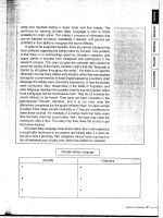
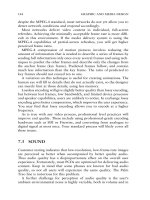
as beam forming or as an adaptive antenna system (AAS). As shown in Figure 5.16, AAS
can be used to limit the signal energy to a narrow beam which increases the range of the cell
and lowers the interference with neighboring systems. Cell capacity can also be increased
by transmitting data to different clients in parallel on the same frequency if they are located
in different directions relative to the base station, as a single subscriber station only receives
its own beam. It is more difficult to use AAS in systems that permit subscribers to roam
freely and at high speed such as UMTS and HSDPA. Here, the bandwidth and processing
power required to constantly adapt the direction of the beam towards a moving subscriber
could easily outweigh the benefits.
Beam forming is achieved by sending the signal via several antennas, which are coupled
with each other electrically. To form a beam, the signal is sent over each antenna with a
calculated phase shift and amplitude relative to the other antennas. There are no moving
parts required for directing the antennas in a certain direction, as the beam-forming effect is
based on the phase and amplitude differences of the signal sent over the antennas. Usually,
AAS is combined with sectorized antennas as described in the GSM and UMTS chapters to
further increase the capacity of the system. In order to form the beam, at least two antennas
are required that are separated by a multiple of the wavelength. At 2.5 GHz, the wavelength
802.16 and WiMAX 285
Figure 5.16 Adaptive antenna systems and beam forming
is equal to (1/2.5 GHz) × speed of light = 12 centimeters. In practice, antennas are typically
separated about 1.5 meters.
To use AAS for 802.16, the standard has been designed in a backwards compatible
way to allow the operation of both AAS capable and standard subscriber stations in the
same cell. At network entry, the subscriber station is informed by the base station if it is
capable of supporting AAS users. If AAS is supported by the base station, each uplink
and downlink subframe has a special AAS area at the end which is preceded by an AAS
preamble sequence. The AAS area has been put at the end of a frame because standard
subscriber stations only listen to the beginning of a frame and their assigned downlink
bursts and thus simply ignore AAS transmissions at the end of the frames. The AAS area
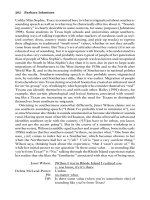
is again split into two parts as shown in Figure 5.17. At the beginning of the AAS area,
‘AAL alert’ slots can be used by subscriber stations to join the network after power on as
DL subframe UL subframe
Preamble
FCH
DL-Burst 1
…
AAS preamble
AAS DL area
Regular
UL bursts
AAL alert slots
AAL UL area
Figure 5.17 TDD uplink and downlink subframes with AAS areas
286 Communication Systems for the Mobile Information Society
described in more detail below. The remaining part of the AAL area can then be used by
the base station to send data simultaneously to several subscribers by forming individual
beams to the subscribers. As for conventional transmissions, the DL-MAP and UL-MAP
messages are used to broadcast information to all subscribers about when data will be sent
to them and when they are allowed to send data. For AAS-capable devices, the DL-MAP
message contains an extended concurrent transmission information element with the system
parameters required for properly receiving the data transmitted in the AAL area.
There are two possibilities for a subscriber station to join the network: if a subscriber station
is located close enough to the base station, it can use the standard network entry procedures
as described in Section 5.6.1. If only a directed beam allows proper communication with
the subscriber station, the subscriber station enters the network by sending a notification
on all available alert slots of the AAS area. The base station receives the transmission and
calculates the parameters required to form a beam towards the subscriber station whenever
data is to be transferred.
In order to optimize the system, a number of MAC management messages are available to
control the AAS parameters for each subscriber station. To keep a beam tuned correctly to a
subscriber station, AAS feedback request and response (AAS-FBCK-REQ + RSP) messages
and AAS beam request and response (AAS-BEAM-REQ + RSP) messages are used. Their
purpose is to request channel measurements and to report their results to fine-tune the beams.
Additionally, the AAS beam select (AAS-BEAM-SELECT) message has been defined to allow
a subscriber station to indicate to the base station that it would like to use a different beam.
Such a message might be used if a beam is directed to several subscribers instead of only one.
5.10 Mobile WiMAX: 802.16e
To improve the position of WiMAX in competition with UMTS and other 3G standards,
the IEEE and the WiMAX forum have decided to enhance the standard with mobility
functionality. As will be shown in the following section, the 802.16e standard introduces
a number of enhancements on all layers of the protocol stack. On the physical layer, a
new multiple access scheme is used. On the MAC layer, many additions were made to
enable true mobility for wireless devices in and between networks. In addition, efficient
power management functionalities for battery-driven devices have been defined. As client
devices are enabled to roam through the network, they are now referred to as mobile stations.
For national and international roaming, a network infrastructure has been standardized to
support mobility management and subscriber authentication over network boundaries. These
functions are outside the scope of the 802.16 standard, as it only describes the air interface.
The WiMAX forum thus extended its work beyond promoting and certifying the technology
and established a networking group to define and standardize how the network behind the
base stations supports roaming and subscriber management. By specifying an end-to-end
network topology, large and even nationwide networks can be built with components of
different vendors.
5.10.1 OFDM Multiple Access for 802.16e Networks
For the 802.16e standard, the IEEE decided not to use the 256-OFDM physical layer used
in first-generation networks. Instead, it was decided to evolve the OFDMA (orthogonal
802.16 and WiMAX 287
Figure 5.18 OFDMA subchannelization in the uplink and the downlink direction
frequency division multiple access) physical layer (PHY). This PHY was already specified in
the previous version of the standard, and functionality has been added to address the require-
ments of mobile subscribers. In OFDM networks, subscribers transmit and receive their
data packets one after another by using all available subchannels. OFDMA allows several
subscribers to transmit and receive data simultaneously in different sets of subchannels. This
principle is shown in Figure 5.18. Depending on the total channel bandwidth, 2048, 1024,
512, or 128 subchannels can be used compared to the fixed number of 256 subchannels of
the OFDM PHY of first-generation networks. In an OFDMA system, the data rate of users
cannot only be adapted by varying the length of their bursts as in OFDM, but also by varying
the number of allocated subchannels.
The OFDMA physical layer is not backwards compatible with the 256-OFDM physical
layer used by first-generation 802.16 networks. In practice, this creates a problem for oper-
ators of first-generation networks. Depending on the capabilities of their base stations and
deployed stationary client devices, they have the following options to update their networks
to support mobile devices:
•
If base stations of a network operator support both OFDM and OFDMA via software
upgrade, one carrier frequency is used for stationary devices while a second carrier
frequency is used for mobile devices.
•
If an operator has deployed stationary client devices that can be upgraded to support
OFDMA, the network and the stationary client devices are updated. Afterwards, the same
carrier frequencies are used to support stationary and mobile devices.
288 Communication Systems for the Mobile Information Society
•
If stationary client devices cannot be upgraded, and the use of additional carriers to support
OFDM and OFDMA devices simultaneously is not desired or not possible, client devices
have to be replaced.
Similar to HSDPA and other 3G technologies, the 802.16e standard introduces HARQ
(hybrid ARQ) for fast error detection and retransmission on the air interface. This is required
for mobile devices, because mobility causes quick signal strength changes which result in
higher error rates. These have to be corrected as quickly as possible to prevent undesired
side effects such as increased delay and retransmissions on the TCP layer which limit the
overall throughput. An introduction to HARQ can be found in Chapter 3, where its use is
discussed for HSDPA. In 802.16, HARQ can be activated per device or per service flow
and the number of simultaneous HARQ processes are negotiated during basic capabilities
exchange (SBC-REQ/RSP) and service activation (DSA-REQ/RSP). Both chase combining
and incremental redundancy are supported to retransmit faulty data blocks. While HSDPA
only uses HARQ to correct errors in the downlink direction, the 802.16 standard uses HARQ
to secure data transmission in both directions. The response times for ACK and NACK
messages are fixed and announced in the UCD and DCD messages. Retransmissions of
faulty HARQ packets are asynchronous, i.e. there is no fixed time window in which faulty
packets have to be retransmitted. In addition, the HARQ mechanism can be combined with
adaptive modulation and coding techniques to quickly adapt to changing signal conditions.
This reduces the number of retransmissions and increases throughput.
5.10.2 MIMO
To further increase transmission speeds, the 802.16e standard specifies MIMO (multiple
input–multiple output) techniques for the network and the client devices. This is especially
the case in urban environments, where a signal is often split into several transmission paths
due to reflection and refraction caused by objects in the direct line of sight between the
transmitter and the receiver. As the transmission paths have different lengths, each copy
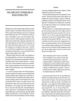
of the signal arrives at a slightly different time at the receiver as shown in Figure 5.19.
For traditional GSM receivers, this phenomenon causes multipath fading due to the quickly
changing paths and the resulting changes in interference of the different paths with each
other. In systems such as UMTS, rake receivers are used to combine the signal energy
received from different paths (see Chapter 3). Instead of trying to compensate for the effects
of multipath transmissions at the receiver side, MIMO uses the effect by using multiple
antennas at both the transmitter and receiver to send data on different paths but on the same
frequency. If the same data stream is sent on all paths, robustness of the transmission is
increased. If a different data stream is sent on each path, the data rate is increased. The
MIMO variant used by 802.16 uses the second approach to increase the data rate.
MIMO requires a dedicated antenna for each transmission path both at the receiver
(multiple input) and the transmitter (multiple output). Furthermore, each transmission path
requires its own transmission and reception chain in the base station and the client device. A
typical MIMO system makes use of two or four paths, which requires two or four antennas
respectively. In current systems, antenna designs are used which already incorporate two
antennas to pick up horizontally and vertically polarized signals created by reflection and
refraction to counter the multipath fading effect (polarized diversity). An example of such
802.16 and WiMAX 289
BS
Direct line of
sight blocked
First transmission
path
Second
transmission
path
obstacle
MS
obstacle
obstacle
obstacle
Figure 5.19 A signal is split into multiple paths by objects in the transmission path
an antenna is shown in Chapter 1, Figure 1.18. MIMO reuses this antenna design. Instead
of combining the horizontally and vertically polarized signals for a single reception chain,
the signals remain independent and are fed into independent reception chains. To send four
individual data streams on the same frequency, two such antennas are required and must
be separated in space by at least a quarter of a wavelength. Together with HARQ, AMC
(adaptive modulation and coding), and AAS (adaptive antenna systems for beam forming),
which were discussed above, MIMO techniques can multiply the overall bandwidth of a base
station and the achievable data rates per client device [11]. It should be noted, that UMTS,
HSDPA and HSUPA (see Chapter 3) do not make use of AAS and MIMO today, as those
standards were developed earlier. Therefore, 802.16e networks using these enhancements
will have a competitive advantage over enhanced UMTS networks. It is expected that the
3GPP will react to this and specify similar techniques in further evolutions of the UMTS
standards.
5.10.3 Handover
The physical layer enhancements ensure a stable connection between the network and the
user while roaming through a cell. To ensure connectivity beyond the user’s serving cell, the
MAC layer was enhanced to enable handovers between cells without dropping the client’s
context with the network. As handovers between cells also require routing changes in the
network behind the base stations, the WiMAX radio and core network have to support the new
mobility functionality. The required network functionalities are described in Section 5.11.
The 802.16e standard defines that both the mobile station and the network are allowed to
initiate a handover. This is in contrast to systems like UMTS, where the network is always
responsible for preparing and initiating a handover. For the handover decision, the mobile
station and the network must be aware of neighboring cells and their reception levels at the
290 Communication Systems for the Mobile Information Society
current location relative to the current serving cell. The network can assist the mobile station
in its search for neighboring cells by sending neighboring cell information in MOB_NBR-
ADV messages. These messages contain the frequencies used by neighboring cells and the
contents of their UCD and DCD messages. If this information is not available in the current
serving cell, the mobile station is also allowed to search for neighboring cells on its own
and retrieve the UCD and DCD messages itself. To synchronize with neighboring cells a
mobile station can then perform an initial synchronization, ranging and association to ensure
that a cell can be used as quickly as possible after a handover. This procedure is called cell
reselection. It should be noted that cell reselection has a different meaning in GSM, GPRS
and UMTS. Here, the term is used for the procedure that is performed by mobile stations in
idle mode to move from one cell to another.
During the time required for the cell reselection procedure, the mobile station cannot
receive data from the cell. To ensure that the cell buffers incoming data during this time,
the network assigns scanning periods to the mobile station. The mobile station can also
request them if required. Once the mobile station returns to the current serving cell, it sends
a measurement report to the network. The network can then use this information to prepare
a handover into a neighboring cell in a similar way as described in Chapters 1 and 3 for
GSM and UMTS. If the mobile station finishes cell reselection early, it can exit this state
by sending a MAC PDU to the serving cell.
A timer is used in the mobile station to renew its associations to neighboring cells
frequently. This is required as signal conditions change when the subscriber changes its
location and the parameters acquired during the association procedures become invalid.
Associations have to be deleted if they cannot be renewed before the timer expires.
Handover times vary depending on how the handover is performed. Longer data transfer
outages are to be expected if an uncoordinated handover is performed in which the mobile
station initiates the handover on its own, is not synchronized to the new cell, and has not
informed the network of the handover. In this case, most steps as described for normal
network entry have to be performed before service can resumed. In order to restore service
flow parameters like the IP addresses used by the mobile terminal, the new cell has to request
information about the subscriber from the previous cell. For this purpose, the handover
message of the mobile station includes the ID of the previous cell.
The interruption of an ongoing data transfer is much shorter if the handover is prepared and
initiated by the network. Figure 5.20 shows the basic principle of the handover procedure, if
the mobile is already associated with the target cell and the target cell is already prepared for
the handover. If these conditions are met, contention-based initial ranging is not required. In
addition, the network can prepare a target cell for a handover by forwarding all subscriber-
related information like authentication information, encryption information, and parameters
of active service flows. Once the mobile station establishes contact with the new cell, basic
capability negotiation, PKM authentication, TEK establishment, and registration messaging
can be skipped and service flows can be immediately reactivated. Figure 5.20 shows such
an optimized handover procedure, which requires non-standardized messaging to exchange
subscriber information between the current serving cell and the new cell.
As the CIDs of active service flows are cell specific, the REG-RSP message at the end
of the handover procedure contains a list that maps the previous service flow identifiers to
those of the new cell. The mobile station can thus keep its IP addresses.
802.16 and WiMAX 291
Figure 5.20 Optimized handover
How the traffic to and from the subscriber is rerouted to the new cell in the network
is out of scope of the 802.16 standard and was defined separately by the WiMAX forum
networking group. These mechanisms are described in Section 5.11.
Despite much optimization, the handover described above still requires the mobile device
to disconnect from the current base station before starting communication with the new
base station. As the resulting transmission gaps may have a negative impact on real-time
applications such as voice and video over IP, additional enhancements are required to
seamlessly handover such connections. For this purpose, two optional handover procedures
have been specified which can be used if the network and the mobile device announce in
registration request and response messages that they support them.
One optional handover procedure is fast base station switching (FBSS) [12]. If used,
the mobile device frequently scans for neighboring base stations and reports measurement
results to the network. Network and mobile device can then agree on using several base
stations simultaneously by putting several base stations in a diversity set list which is kept
in both the network and the client device. Adding and deleting cells in the diversity set is
performed by the mobile sending MOB_MSHO_REQ messages. If the diversity list contains
more than a single base station, the mobile station can dynamically inform the network
from which base station it would like to receive data in the downlink direction via another
MOB_MSHO_REQ message. The network is also allowed to trigger the handover process by
sending a MOB_BSHO_REQ message. At any time, only a single base station is responsible
for forwarding data to the mobile device in the downlink direction.
FBSS requires all base stations in the diversity set to be synchronized and to use a
synchronized frame structure. This way, the mobile device must not resynchronize itself to a
new base station in the downlink direction, which minimizes the interruption caused by the
292 Communication Systems for the Mobile Information Society
handover. In addition, all base stations included in the diversity set have to operate on the
same frequency. As neighboring base stations transmitting on the same frequency interfere
with each other, optional beam forming (AAS) and power adaptation functionality in the
downlink direction help to reduce this unwanted side effect.
The base station that is responsible for sending data to the subscriber in the downlink
direction is referred to as the anchor base station. Apart from data transfer, the anchor base
station is also responsible for the administration of the subscriber context. When an FBSS
handover is performed, the new base station assumes control of the context.
In the uplink direction, all base stations of the diversity set listen to transmissions of the
mobile device. This requires a further logical synchronization in the radio network between
the base stations in the diversity set, as all base stations have to schedule uplink opportunities
for a mobile device at the same time. Each base station then forwards only correctly received
frames to the core network. This requires functionality in the radio network to combine the
different uplink data streams in order to forward only a single uplink data stream to the core
network.
The macro diversity handover (MDHO) is an even smoother form of handover. Like
the FBSS handover, it is also optional. When MDHO is activated for a connection, e.g.
due to effects such as deteriorating signal conditions, all base stations of the diversity set
synchronously transmit the same data frames in the downlink direction. As all base stations
transmit on the same frequency, the mobile device can either use RF energy combining or
soft data combining to benefit from the multiple simultaneous transmissions. If the reception
of one of the base stations in the diversity set becomes too weak, it is removed from the
diversity set. Additions and deletions in the diversity set are performed by the mobile using
MOB_MSHO_REQ messages. As several base stations communicate with the client device
simultaneously, anchor responsibilities only have to be transferred to another base station if
the current anchor base station is removed from the diversity set. If only one base station
remains in the diversity set, the MDHO state ends and the handover has been performed
without any interruption of the ongoing data transfer.
In the uplink direction, the MDHO and FBSS handover behavior is identical.
The concept of an anchor base station cannot be found in other systems such as GSM,
UMTS, or CDMA. In these systems, handovers are controlled from a central controlling
element in the radio network such as a BSC or an RNC. In 802.16e radio networks on the
other hand, the anchor base station concept has been introduced because the base stations
organize themselves. The functionalities of the radio controller node between the base stations
and the gateway to the core network (e.g. an SGSN) have been partly put into the base
stations and party into the access service network gateway (ASN-GW) node, which is further
described in Section 5.11.
5.10.4 Power-Saving Functionality
While a connection is active, a mobile terminal requires a considerable amount of energy
to keep listening to the network for incoming data. To increase the battery operating time,
the mobile can reduce its energy consumption in times of low activity by entering power-
save mode. Several power-saving modes have been defined in the standard and each active
service flow can use a different power-saving mode. As a consequence, the mobile can
802.16 and WiMAX 293
only deactivate its transceiver at times in which all active service flows have entered the
power-saving state.
Power-saving class I is activated by the mobile station and confirmed by the base station.
In this mode, active periods with a static length alternate with sleeping periods which increase
over time. As the length of the sleeping periods increase over time up to a predefined
value, activity of the mobile and energy consumption is automatically reduced over time.
If data arrives for the mobile station while in this mode the network aborts the sleep mode
by sending a MOB_TRF-IND message during an active period. The mobile station also
automatically leaves the sleep mode if data has to be sent in the uplink direction. As no data
can be sent or received in this mode, power-saving class I is most suitable for non-real-time
and background service flows.
For real-time services, power-saving class II introduces fixed activity periods that alternate
with predefined sleeping periods. In contrast to class I, data can be exchanged in active
phases in both directions without leaving the overall power-save mode state. This is important
for real-time services, as data with fixed or varying bandwidth requirements is constantly
transmitted. By choosing appropriate activity and sleeping periods the system can ensure
sufficient bandwidth for the connection and required delay times can be met. This is possible
because real-time services do not require the full bandwidth offered by the air interface.
Power-saving class II thus offers the system the possibility of limiting transmissions to
certain frames, which helps to save battery power by deactivating the transceiver in a mobile
station during frames which are sent in the sleeping periods.
Power-saving class III has been designed for management connections and broadcast
services. When the mobile requests such a connection to be set into this sleep mode variant,
the base station calculates a sleep window during which no broadcast data or management
message needs to be sent in the downlink direction. The mobile station then enters sleep
mode for the granted duration and becomes active again automatically once the sleeping
period has expired.
5.10.5 Idle Mode
To further reduce power consumption during times of longer inactivity the 802.16e standard
introduces an optional idle mode for mobile stations. Its basic functionality is similar to
the concept of a UMTS UE in idle mode with an active PDP context (see Chapter 3). As
in UMTS the mobile station retains its service flows, i.e. its IP addresses, while no active
communication connection is maintained with the network. If new data is received by the
core network for a mobile station in idle mode, a paging procedure has to be performed in all
cells belonging to the same paging group. Paging a mobile in several cells requires a central
paging controller in the network. As the 802.16 standard only defines the air interface part
of the network, the implementation of this function is out of the scope of the standard and
has been left for further standardization by the WiMAX forum networking group.
The concept of a paging group is similar to the UMTS concept of a location area. Unlike
location areas, paging groups can overlap in the network and a cell can belong to several
paging groups simultaneously. This is shown in Figure 5.21. This prevents frequent paging-
group updates of mobiles in paging-group border areas.
While in idle mode, the mobile station can roam to cells belonging to the same paging
group without performing a handover or notifying the network about the cell change. From
294 Communication Systems for the Mobile Information Society
Figure 5.21 Overlapping paging groups
time to time, the mobile station has to send a location update to the network in order to keep
the service flows active. For most of the time, the mobile station’s transceiver is deactivated
while in idle mode. In order to be able to react to incoming paging messages, the mobile has
to periodically reactivate its transceiver to listen for incoming paging messages in which the
mobile is identified via its MAC address. Furthermore, the mobile station has to periodically
check the reception level of the current serving cell, search for neighboring cells, and perform
and select a new serving cell if required.
If a mobile station receives a paging message, it has to perform ranging and network
entry procedures. As the base station can retrieve the context of the mobile station from the
mobility management controller in the network, most steps of the network entry procedure
can be skipped in a similar way as described above for a handover. The mobility management
controller function is typically implemented together with the paging controller function in
a central element in the network.
5.11 WiMAX Network Infrastructure
Many features such as mobility management for handover and idle mode paging require
coordination between different nodes of the network. How these features are implemented
is beyond the scope of the 802.16 specification, as it only deals with the air interface
between base stations and client devices. Other features, such as national and international
roaming between networks, user authentication, administration, and billing, are also not part
of the 802.16 specification. As many vendors are developing mobile devices and network
infrastructure components, a standard is required that describes these functionalities. This
802.16 and WiMAX 295
ensures interoperability of networks and components of different manufacturers within the
network.
The main benefits of standardized WiMAX networks for subscribers are standardized
hardware and software that can be mass-produced and can thus be competitively priced
and used in any network. For the operator, standardized components and functionalities
ensure competition among vendors resulting in competitive pricing of network components.
In addition, standardized interfaces for roaming enable operators to offer services to visiting
subscribers.
The following sections describe the main aspects of the WiMAX network infrastructure,
which is standardized by the networking group of the WiMAX forum. Members of this body
are vendors such as Intel, Samsung, Motorola, Nortel, and many others who are involved in
developing products for the WiMAX ecosystem ranging from chipsets, user devices, base
stations, and other network infrastructure. As specification work for the network infrastructure
started relatively late in the overall design process, many first-generation networks are
proprietary and not interoperable with each other. In the course of the evolution of these
networks it is expected that they will be upgraded to be compliant to the WiMAX forum
network infrastructure standards to benefit from the advantages listed above.
5.11.1 Network Reference Architecture
The network reference architecture of the WiMAX forum networking group specifies a
number of reference points between logical functions of the network. Therefore network
vendors can choose between different alternatives of where to put a number of functionalities
in the radio and core network. Figure 5.22 shows one of the possible architectures [13]
that is likely to be implemented by vendors. Similar to other types of wireless wide area
networks, a WiMAX network is split into radio access and core network parts. The radio
access network part is referred to as the access service network (ASN). It is connected to the
core network via the ASN-gateway (ASN-GW) and the R3 reference point. A large network
can comprise more than a single ASN if several ASN-GWs are required for the management
of the radio access network.
An ASN contains two logical entities, the ASN-GW and the base stations. Compared
to GSM and UMTS, it should be noted that the architecture no longer contains an entity
between the gateway to the core network and the cells such as an RNC. The functionalities
of this node, such as radio channel management and mobility management, were moved
partly to the base stations and partly to the ASN-GW.
Another difference from networks discussed in Chapters 1 to 3 is the use of the IP protocol
on all interfaces (reference points) between all nodes of the network. This reduces complexity
and cost as IP has become the dominant network protocol and can be used with almost any
kind of underlying transport technology. For short distances between nodes, Ethernet over
twisted pair copper cables can be used as it is a very cheap transport technology. For larger
distances, optical technologies are most suitable, and IP is transported via ATM or via optical
Ethernet. As IP is used with all technologies, only a single WiMAX-specific software stack
is required for the different transmission technologies. This reduces cost and complexity. As
WiMAX networks no longer use circuit-switched connections, using IP on all interfaces is
easily possible.
296 Communication Systems for the Mobile Information Society
Figure 5.22 WiMAX network reference architecture
Fast base station switching (FBSS) and macro diversity handovers (MDHO) require a close
synchronization between base stations. As the basic IP protocol does not ensure constant
latency and bandwidth for a connection, IP QoS mechanisms have to be used over the R8
reference point. The reference points/interfaces inside the ASN (R6 and R8) have not been
specified in the first version of the WiMAX network infrastructure standard and thus such
solutions are proprietary.
Due to the use of IP on all interfaces, WiMAX network components can be directly
connected with each. For longer distances, standard IP routers can be used to forward both
user data and signaling traffic between the components. No special WiMAX software is
required in the IP routers. This enables operators to use cheaply available IP hardware. In
addition, operators can lease IP bandwidth from other companies, for example to connect
base stations to the ASN-GW. To ensure security and confidentiality, encryption (e.g. IPSec)
and tunneling mechanisms should be used on these interfaces.
Apart from offering direct Internet access, operators may also be interested in offering
value-added services such as voice and video over IP, push to talk, voice and video mail,
IP television, and other advanced multimedia services. It is likely that operators will host
a variety of multimedia nodes in their core networks such as the IP multimedia subsystem
(IMS, see Chapter 3).
Authentication, authorization, and accounting (AAA) is another functionality of the core
network. It is used to flexibly bill services such as Internet access and IMS services used by
the subscriber. To allow subscribers to roam between networks, AAA is another important
functionality that has to be standardized in order to be interoperable. For this purpose, the
R5 reference point has been defined to allow foreign networks to access the AAA server in
the home network of a subscriber.
802.16 and WiMAX 297
5.11.2 Micro Mobility Management
When establishing a connection to the network, an IP address is assigned to the subscriber
device. When moving between base stations, the IP address has to remain the same to
preserve communication connections established by higher layer applications. As routing
decisions in the network are based on IP addresses and static routing tables, the mobility of
the subscriber has to be hidden from most of the network. This is done in several ways.
While moving between base stations of a single ASN, the mobility of the subscriber is
managed inside the ASN, and the ASN-GW hides the mobility of the subscriber from the
core network and the Internet (R6 mobility). As long as the subscriber roams between base
stations connected to the same ASN-GW, all IP packets flow through the same ASN-GW.
Inside the ASN, IP tunnels are used to direct IP packets to the base station currently serving
a subscriber. Three layers of tunnels are used as shown in Figures 5.23 and 5.24. On the first
layer, each base station is connected to the ASN-GW via a secure and possibly encrypted IP
tunnel to protect the data flowing between the two nodes. This allows the use of third-party
networks to forward traffic between a base station and the ASN-GW.
Inside the base station IP tunnel, a further IP tunnel is established per subscriber. When
a subscriber roams from one base station to another, the ASN-GW redirects this tunnel to
another base station tunnel. By tunneling the IP packets through the IP network, only the
routing table of the ASN-GW has to be modified when the subscriber roams to another cell.
The routing tables of routers in between the ASN-GW and the base stations do not have to
be altered, as the routing is based on the IP address of the base stations. The IP packets for
a client device including its IP address is embedded in the payload part and is thus not used
for the routing process inside an ASN.
This micro mobility management concept is similar to that of the GPRS tunneling protocol
(GTP) which is used in GPRS and UMTS networks to tunnel user data between the GGSN
and the SGSN (see Chapter 2). It should be noted, however, that in GPRS and UMTS
Figure 5.23 Micro mobility management inside an ASN
298 Communication Systems for the Mobile Information Society
10.0.0.1
195.36.219.196
10.0.0.2
10.0.0.3
Web
server
193.99.144.85
BS tunnel
BS tunnel
ASN-GW
BS
BS
R6 reference point
This part of the
route remains
unaltered
Figure 5.24 Subscriber tunnel after handover to new cell
networks IP tunneling is used in the core network while in WiMAX networks IP tunneling
is used in the radio access network (ASN). In the WiMAX core network, mobile IP is used
for subscriber mobility management, which is discussed in the next section.
A client device can have several active service flows, each with its own IP address. To
separate these service flows, a third tunnel layer is used.
The 802.16 standard offers several convergence sublayers on the air interface to embed
IP packets in a MAC frame. The WiMAX networking group has chosen the IP convergence
sublayer (CS) as shown on the left side of Figure 5.1 for its network architecture [14]. This
CS only generates a small overhead compared to other CS and reduces the complexity of
developing dual-mode devices capable of seamlessly roaming between WiMAX and other
networks types such as UMTS.
5.11.3 Macro Mobility Management
If a subscriber roams to a base station of another ASN, traffic needs to be redirected
to the new ASN. This can be done in several ways. If the anchor ASN-GW is to be
maintained, the traffic from and to the core network continues to flow through the ASN-GW
of the subscriber’s original ASN. The original ASN then forwards all user data frames and
management messages to the new ASN via the R4 reference point shown in Figure 5.22.
While one of the cells of the old ASN is still part of the diversity set of the enhanced
FBSS or MDHO handover variants, the A8 interface can be used if present to include cells
of several ASNs in the diversity set.
To optimize the routing in the network, it might be beneficial at some point to change the
route of the incoming and outgoing traffic of a user to flow only through the ASN-GW of the
new ASN. For this dynamic rerouting, mobile IP (MIP) is used between the ASN-GW and
802.16 and WiMAX 299
ASN-GW
ASN-GW
Core Network
Web
server
193.99.144.85
HA
195.36.219.196
3. MIP tunnel between HA
and ASN-GW (Proxy-MIP)
64.236.23.28
4. Care-of IP
address (COA) is
the end point of the
tunnel
2. Address for the client
device taken from the
address pool
5. IP packet with
destination address
195.36.219.196
forwarded through
micro mobility
management tunnels
1. Packets are
always delivered
to the HA
first
MS
(195.36.219.196)
IP pool
Figure 5.25 Principle of (proxy) mobile-IP in a WiMAX network
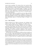
the subscriber’s home network. The principle of MIP is shown in Figure 5.25. If a subscriber
establishes an IP version 4 connection, the ASN-GW acts as a proxy and terminates the MIP
connection instead of the mobile device (proxy-MIP). This allows the use of a standard IP
version 4 stack on the client device without MIP capability. During the connection setup
procedure the ASN-GW registers with the MIP home agent (HA) in the user’s home network
and sends its local IP address to the HA. This IP address is also known as the user’s care-of
IP address (COA) as it can change at any time during the lifetime of the connection. The
HA then assigns an IP address for the user and returns it to the ASN-GW. The ASN-GW
in turn forwards this IP address to the client device, which will use it for all incoming and
outgoing data packets. The IP address assigned by the HA to the ASN-GW (and thus to
the client device) belongs to a local pool of IP addresses and all data packets which use
this IP address as the destination will always be routed to the HA. If an external host sends
an IP packet to the mobile device, it is routed to the home agent first. There the packet is
forwarded inside an MIP tunnel to the COA, i.e. the ASN-GW. The ASN-GW is the end of
the MIP tunnel and in turn forwards the IP packet through the micro mobility management
tunnels described in the previous section. Any change in the COA, i.e. a change to another
ASN-GW, is transparent to external hosts and routers. From their point of view, the home
agent remains the destination for the packet.
In the reverse direction, mobile devices use the IP address assigned by the HA as the
originating IP address of a packet to an external host and not the COA (of which it is not
even aware as the ASN-GW acts as MIP proxy). As routing decisions in an IP network are
not based on the originating IP address but on the terminating IP address of a packet, it is
routed directly to the external host instead of via the HA.
If a client device uses IPv6, no proxy MIP mechanisms are required in the ASN-GW, as
IPv6 natively offers MIP functionality.
300 Communication Systems for the Mobile Information Society
5.12 Comparison of 802.16 with UMTS, HSDPA, and WLAN
As has been shown in this chapter, wireless LANs (802.11) and the wireless MANs defined
in the IEEE 802.16 standard do not have much in common. While WLAN is designed for
home and office use to interconnect devices wirelessly with each other and the Internet
over short distances, 802.16 aims to offer broadband connections over larger distances.
This requires a fundamentally different approach on the first two layers of the protocol
stack compared to WLAN. By offering time and frequency division duplexing, 802.16
systems can be used in both licensed and unlicensed bands. WLAN and 802.16 are thus
complementary technologies, as some devices for home and office use may combine them
by offering wireless connectivity via WLAN to notebooks, PDAs, and other devices, while
using 802.16 as a backhaul technology to connect the local network to the Internet. By
providing fast Internet access with speeds between 1 and 10 Mbit/s over distances of several
kilometers in a real environment, 802.16 networks can compete with other metropolitan
network technologies such as UMTS and HSDPA, which have been discussed in Chapter 3.
Given similar bandwidths allocations, both systems are capable of delivering fast Internet
access to both private and business users at comparable speeds. In contrast to HSDPA,
which is a natural evolution for UMTS networks and will thus be mostly used by incumbent
wireless operators, 802.16 is an interesting technology for new network operators that want
to compete with other methods of broadband fixed and wireless Internet access. While
HSDPA is designed for both fixed and mobile use, the 802.16-2004 standard is limited to
stationary wireless clients with internal antennas if they are close enough to the base station,
or roof-mounted directional antennas for larger distances. This limitation greatly reduces
the complexity of the solution, which in turn helps to reduce network infrastructure costs.
While systems like UMTS and CDMA1x are end-to-end network systems with sophisticated
service architectures to allow national and international roaming of subscribers, the 802.16-
2004 standard only deals with the first two layers of the network protocol stack. Thus, such
networks are limited to regional coverage. The 802.16e extension to the standard aims to
improve the situation by adding mobility, and notebook component manufacturers such as
Intel have shown interest in delivering chipsets which support the mobility extension of the
802.16 the standard. In addition a network architecture has been defined that allows national
and international roaming. At the time of publication, the first 802.16 networks only support
stationary devices, with the first notebooks using 802.16e mobility chipsets expected in the
2007 timeframe. This will help to further increase the competition with UMTS and CDMA1x
networks, which should result in lower prices for end customers. 802.16 should prove to be
the technology of choice for offering fast Internet access in rural areas, where other forms
of broadband access such as DSL or cable are not economically viable. In countries where
networks such as UMTS and CDMA1x are available, this will increase competition and will
help to drive operators to evolve their networks in order to hold on to their market shares
and revenues. In developing countries, 802.16 allows operators to offer Internet access to
a broader market in the same way that GSM networks have allowed operators to deliver
telephony services to millions of people without access to a public fixed-line telephony
network. Like other technologies described in this book, 802.16 networks have not appeared
in the marketplace as quickly as predicted by analysts, sales managers, and the media.
However, if the long-term success of these systems can be taken as an example, networks
based on 802.16 should have an interesting and exciting future.
802.16 and WiMAX 301
5.13 Questions
1. What are the theoretical and practical bandwidths offered by an 802.16 system when
used for connecting end users to the Internet?
2. How does the coding scheme influence user throughput and overall throughput in
a cell?
3. Why does the 802.16 support both FDD and TDD mode of operation?
4. What is a service flow?
5. Which difficulties are encountered when a license-free band is used for the operation of
an 802.16 cell?
6. Why is fragmentation and packing used for transmitting IP packets over the 802.16 air
interface?
7. What is the difference between the coordination scheme used in WLAN (802.11) and
the one used in 802.16 systems?
8. Why is the MAC address of a device not used in the header of a MAC packet?
9. Which steps are required for a subscriber station to connect to the network?
10. How can a mesh network extend the range of a base station?
11. What is the advantage of using an adaptive antenna system?
12. What is the basic architectural difference between a WiMAX radio network and other
radio networks described in this book?
13. What is fast base station switching?
14. How can MIMO improve transmission speeds?
Answers to these questions can be found on the companion website for this book at
.
References
[1] The Institute of Electrical and Electronics Engineers, Inc., ‘802.16-2004 IEEE Standard for Local and
Metropolitan Area Networks – Part 16: Air Interface for Fixed Broadband Wireless Access Systems’, IEEE
standard, October 2004.
[2] The Worldwide Interoperability for Microwave Access Forum, ‘IEEE 802.16a Standard and WiMAX Igniting
Broadband Wireless Access’, white paper, available at .
[3] David Johnston and Hassan Jaghoobi, ‘Peering into the WiMAX Spec: Part 1’, white paper, January 2004,
available at .
[4] WiMAX Forum, Eugene Crozier and Allen Klein, ‘WiMAX’s Technology for LOS and NLOS Environments’,
white paper, available at .
[5] Arunabha Gosh, David R. Wolter, Jeffrey G. Andrews and Runhua Chen, ‘Broadband Wireless Access with
WiMax/802.16: Current Performance Benchmarks and Future Potential’, February 2005, IEEE Communica-
tions Magazine, pp. 129–36.
[6] Govindan Nair et al., ‘IEEE 802.16 Medium Access Control and Service Provisioning’, August 2004, Intel
Technology Journal, 8(3), 212–28.
[7] K. Sollins, ‘RFC 1350 – The TFTP Protocol (Revision 2)’, Internet RFC Archives, July 1992.
[8] R. Droms, ‘RFC 2131 – Dynamic Host Configuration Protocol’, Internet RFC Archives, March 1997.
[9] J. Postel and K. Harrenstien, ‘RFC 868 – Time Protocol’, Internet RFC Archives, May 1983.
[10] R. Housley et al., ‘RFC 2459 – Internet X.509 Public Key Infrastructure Certificate and CRL Profile’, Internet
RFC Archives, January 1999.
302 Communication Systems for the Mobile Information Society
[11] A. Jeffries et al., ‘New Enabling Technologies: Building Blocks for Next-Generation Wireless Solutions’,
Nortel Technical Journal, 2, July 2005, available at .
[12] Bill Cage et al., ‘WiMAX: Untethering the Internet User’, Nortel Technical Journal, 2, July 2005, available
at .
[13] Parviz Yegani, ‘WiMAX Overview’, Presentation for the IETF-64 Conference, November 2005.
[14] Max Riegel, ‘IEEE 802.16 Convergence Sublayer’, Presentation for the IETF-64 Conference, November 2005.
6
Bluetooth
To connect devices such as computers, printers, mobile phones, PDAs and headsets with
each other, a number of cable and infrared technologies have been developed over the years.
Wired connections are mostly used for big or stationary devices, while infrared connections
have advantages for small or mobile devices. In practice, however, the use of wired or
infrared connections is often complicated and also not very practical in many situations.
The Bluetooth technology offers an ideal solution to this problem. In order to show the
possibilities of Bluetooth, this chapter provides an overview of the physical characteristics
and the general functionality of the system, as well as the organization and functionality
of the protocol stack. We then discuss the concept of Bluetooth profiles and demonstrate
how they can be used in practice. While Bluetooth and wireless LAN are two very different
systems, they also have many things in common. Thus, a comparison is made between the
two technologies at the end of the chapter to show which technology is the best choice for
which application.
6.1 Overview and Applications
Due to the ongoing miniaturization and integration, more and more small electronic devices
are used nowadays in everyday life. Bluetooth enables these devices to wirelessly commu-
nicate with each other without a direct line-of-sight connection. This enables a wide range
of new applications and possibilities. Some of them are described below.
The mobile phone is at the center of many new applications. In addition to normal voice
telephony, mobile phones are also used today to connect to the Internet. Apart from the
embedded WAP browser, external devices like notebooks or PDAs can also use the mobile
phone as a gateway to the Internet. In order to establish a connection between the devices, the
mobile phone simply has to be in range and does not even have to be taken out of a pocket
or case. Thus, it is no longer necessary to connect devices with a cable or position them in
a certain way for an infrared source. This is a big advantage especially when traveling in
trains, buses, cars or the metro, where there is usually only limited space and freedom of
movement.
The Bluetooth module embedded in a mobile phone can be used for many other things
as well. Calendar entries, addresses, notes, etc., which are stored on a mobile phone, can be
Communication Systems for the Mobile Information Society Martin Sauter
© 2006 John Wiley & Sons, Ltd
304 Communication Systems for the Mobile Information Society
quickly exchanged with other personal devices like PDAs, notebooks, or devices of friends
while they are at close range.
Many mobile phones are also equipped with a photo camera and file systems in order to
take and store pictures. By using Bluetooth, these pictures can be sent quickly and for free
to other mobile phones, PDAs, notebooks and PCs in the vicinity.
Mobile phone file systems are not only suitable for photos but can also be used for a great
variety of other file types. Thus, it is also possible to send files from a PC or notebook to
a mobile phone and retrieve the information at another location with another device. This
application replaces a universal serial bus (USB) memory stick and the files can be copied
to and from the mobile phone without attaching a cable or plugging the phone into a USB
port of a PC.
Speech transmission between a mobile phone and a headset is another interesting applica-
tion for Bluetooth. For an incoming call, the user simply accepts the call by pressing a button
on the Bluetooth headset. Some Bluetooth headsets even have a small display in which the
number or the name of the caller is displayed. For outgoing calls, the mobile phone’s voice
recognition feature can be used and thus a single button on the headset is enough to establish
an outgoing connection. All this can be done while the phone remains in your pocket!
Bluetooth, however, is not limited to use with mobile phones. As great emphasis has been
put on easy and fast configuration of a new connection, Bluetooth is also ideally suited for
data transmission between PCs, notebooks and PDAs. With only minimal configuration of
the devices, it is possible to exchange files, calendar entries and notes and to synchronize
calendars and address books.
Furthermore, Bluetooth can be used to connect PCs with peripheral devices. Bluetooth-
enabled printers, mouse devices, keyboards and modems are available in order to reduce the
number of cables and clutter on the desktop.
Bluetooth technology can also be used for mobile game consoles, where the technology
can be used to network the consoles of different players with each other.
As there are a great number of different Bluetooth devices from different vendors, reliable
interoperability is of utmost importance for the success of Bluetooth. This is ensured by the
Bluetooth standard and interoperability tests, which are performed during so-called ‘unplug
fests’ and by certified Bluetooth qualification test facilities [1] for final products.
Table 6.1 lists the different Bluetooth protocol versions. Generally, a new version is always
downward compatible to all previous versions. This means that a Bluetooth 1.1 device is
still able to communicate with a Bluetooth 2.0 device. Functionality, however, that has been
introduced with a newer version of the standard, can of course not be used with a device
that supports only a previous version of the standard.
6.2 Physical Properties
Up to version 1.2 of the standard, the maximum data rate of a Bluetooth transmission channel
is 780 kbit/s. All devices that communicate directly with each other have to share this data
rate. The maximum data rate for a single user thus depends on the following factors:
•
number of users that exchange data with each other at the same time;
•
activity of the other users.
Bluetooth 305
Table 6.1 Bluetooth versions
Version Approved Comment
1.0B Dec. 1999 First Bluetooth version, which was only used by a few first-generation
devices
1.1 Feb. 2001 This version corrects a number of errors and ambiguities of the previous
version (errata list). This further increases the interoperability between
devices of different vendors
1.2 Nov. 2003 Introduction of the following new features:
•
faster discovery of nearby Bluetooth devices. Devices can now also be
sorted on the signal quality, as described in Section 6.4.2
•
fast connection establishment, see Section 6.4.2
•
adaptive frequency hopping (AFH), see Section 6.4.2
•
improved speech transmission, e.g. for headsets (eSCO) as described in
Sections 6.4.1 and 6.6.4
•
improved error detection and flow control in the L2CAP protocol
•
new security functionality: anonymous connection establishments
2.0 2004 Enhanced data rates extends the Bluetooth 1.2 specification with faster
data transmission modes. Further details can be found in Sections 6.2 and
6.4.1. The complete standard can be found in [2]
The highest transmission speed can be achieved if only two devices communicate with
each other and only one of them has a large amount of data to transmit. In this case,
the highest data rate that can be achieved is 723 kbit/s. After removing the overhead, the
resulting data rate is about 650 kbit/s. The remaining bandwidth for the other device to
send data in the reverse direction is about 57 kbit/s. This scenario occurs quite often, for
example during web surfing or when transferring a file. In these cases, one of the two
devices sends the bulk of the data while the other device only sends small amounts of data
for requests or acknowledgment. Figure 6.1 shows the achievable speeds for this scenario
on the left.
If both ends of the connection need to send data as quickly as possible, the speed that can
be achieved at each side is about 390 kbit/s. Figure 6.1 shows this scenario in the middle
section.
If more than two devices want to communicate with each other simultaneously, the
maximum data rate per device is further reduced. This is shown on the right side of Figure 6.1.
In 2004, the Bluetooth 20 + EDR (enhanced data rate) standard [2] was released. This
enables data rates of up to 2.178 Mbit/s by using additional modulation techniques. This is
discussed in more detail in Section 6.4.1.
In order to reach these transmission speeds, Bluetooth uses a channel in the 2.4 GHz ISM
(industrial, scientific, and medial) band with a bandwidth of 1 MHz. Gaussian frequency
shift keying (GFSK) is used as modulation up to Bluetooth 1.2, while DQPSK and 8DPSK
are used for EDR packets. Compared to a 22 MHz channel required for wireless LAN, the
bandwidth requirements of Bluetooth are quite modest.
For bi-directional data transmission, the channel is divided into timeslots of 625 microsec-
onds. All devices that exchange data with each other thus use the same channel and are
306 Communication Systems for the Mobile Information Society
Figure 6.1 Three examples of achievable Bluetooth data rates depending on the number of users and
their activity
assigned timeslots at different times. This is the reason for the variable data rates shown in
Figure 6.1. If a device has a large amount of data to send, up to five consecutive timeslots
can be used before the channel is given to another device. If a device has only a small
amount of data to send, only a single timeslot is used. This way, all devices that exchange
data with each other at the same time can dynamically adapt their use of the channel based
on their data buffer occupancy.
As Bluetooth has to share the 2.4 GHz ISM frequency band with other wireless tech-
nologies like wireless LAN, the system does not use a fixed carrier frequency. Instead, the
frequency is changed after each packet. A packet has a length of either one, three or five
slots. This method is called frequency hopping spread spectrum (FHSS). This way, it is
possible to minimize interference with other users of the ISM band. If some interference is
encountered during the transmission of a packet despite FHSS, the packet is automatically
retransmitted. For single slot packets (625 microseconds), the hopping frequency is thus
1600 Hz. If five slot packets are used, the hopping frequency is 320 Hz.
A Bluetooth network, in which several devices communicate with each other, is called
a piconet. In order to allow several Bluetooth piconets to coexist in the same area, each
piconet uses its own hopping sequence. In the ISM band, 79 channels are available. Thus,
it is possible for several wireless LAN networks and many Bluetooth piconets to coexist in
the same area as shown in [3].
The interference created by wireless LAN and Bluetooth remains low and hardly noticeable
as long as the load in both the wireless LAN and the Bluetooth piconet(s) is low. As has
been shown in Chapter 4, a wireless LAN network only sends short beacon frames while
no user data is transmitted. If a wireless LAN network, however, is highly loaded, it blocks
a 25 MHz frequency band for most of the time. Therefore, almost a third of the available
channels for Bluetooth are constantly busy. In this case, the mutual interference of the two
Bluetooth 307
systems is high, which leads to a high number of corrupted packets. In order to prevent this,
Bluetooth 1.2 introduces a method called adaptive frequency hopping (AFH). If all devices
in a piconet are Bluetooth 1.2 compatible, the master device (see Section 6.3) performs a
channel assessment to measure the interference encountered on each of the 79 channels. The
link manager (see Section 6.4.3) uses this information to create a channel bitmap and marks
each channel that is not to be used for the frequency-hopping sequence of the piconet. The
channel bitmap is then sent to all devices of the piconet and thus, all members of the piconet
are aware of how to adapt their hopping sequence. The standard does not specify a single
method for channel assessment. Available choices are the received signal strength indication
(RSSI) method or other methods that exclude a channel due to a high packet error rate.
Bluetooth 1.2 also offers dual mode devices, which are equipped with both a wireless LAN
and a Bluetooth chip, to inform the Bluetooth stack which channels are to be excluded from
the hopping sequence. In practice, this is quite useful, as the device is aware which wireless
LAN channel has been selected by the user, and it can then instruct the Bluetooth module
to exclude 25 consecutive channels from the hopping sequence.
As Bluetooth has been designed for small, mobile and battery-driven devices, the standard
defines three power classes. Devices like mobile phones usually implement power class 3
with a transmission power of up to one milliwatt. Class 2 devices send with a transmission
power of up to 2.5 milliwatts. Class 1 devices use a transmission power of up to 100
milliwatts. Only devices such as some USB Bluetooth sticks for notebooks and PCs are
usually equipped with a class 1 transmitter. This is due to the fact that the energy consumption
compared to a class 3 transmitter is very high and should therefore only be used for devices
where the energy consumption does not play a critical role. The distances that can be
overcome with the different power classes are also quite different. While class 3 devices
are usually designed to work reliably over a distance of 10 meters or through a single wall,
class 1 devices can achieve distances of over 100 meters or penetrate several walls. The
range of a piconet also depends on the reception qualities of the devices and the antenna
design. In practice, newer Bluetooth devices have a much-improved antenna and receiver
design, which increases the size of a piconet without increasing the transmission power of
the devices. All Bluetooth devices can communicate with each other, independently of the
power class. As all connections are bi-directional, however, it is always the device with the
lowest transmission power that limits the range of a piconet.
Security plays an important role in the Bluetooth specifications. Thus, strong authentication
mechanisms are used to ensure that connections can only be established if they have been
authorized by the users of the devices that want to communicate. Furthermore, encryption is
also a mandatory part of the standard and must be implemented in every device. Ciphering
keys can have a length of up to 128 bits and thus offer good protection against eavesdropping
and hostile takeover of a connection.
6.3 Piconets and the Master/Slave Concept
As previously described, all devices that communicate with each other for a certain time
form what is called a piconet. As shown in Figure 6.2, the frequency hopping sequence of the
channel is calculated from the hardware address of the first device that initiates a connection to
another device and thus creates a new temporary piconet. Therefore devices can communicate
with each other in different piconets in the same area without disturbing each other.
308 Communication Systems for the Mobile Information Society
Figure 6.2 By using different hopping sequences, many piconets can coexist in the same area
A piconet consists of one master device that establishes the connection and up to seven
slave devices. This seems to be a small number at first. However, as most Bluetooth
applications only require point-to-point connections as described in Section 6.1, this limit is
therefore sufficient for most applications. Even if Bluetooth is used with a PC to connect
with a keyboard and a mouse, there are still five more devices that can join the PC’s piconet
at any time.
Each device can be a master or a slave of a piconet. Per definition, the device that initiates
a new piconet becomes the master device as described in the following scenario.
Consider a user who has a Bluetooth-enabled mobile phone and headset. After initial
pairing of the two devices (see Section 6.5.1), the two devices can establish contact with
each other at any time and thus form a piconet for the duration of a phone call. At the end of
a phone call the Bluetooth connection ends as well, and the piconet thus ceases to exist. In
the case of an incoming call, the mobile phone establishes contact with the headset and thus
becomes master of the connection. In the reverse case the user establishes an outgoing phone
call by pressing a button on the headset and by using the voice-dialing feature of the mobile
phone. In this case, it is the headset and not the mobile phone that establishes the connection
and thus the headset becomes the master of the newly established piconet. If another person
in the vicinity also uses a Bluetooth-enabled mobile phone and headset, the two piconets
overlap. As each piconet uses a different hopping sequence, the two connections do not
interfere with each other. Because of the initial pairing of the headset and the mobile phone
it is ensured that each headset finds its own mobile phone and thus always establishes a
connection for a new phone call with the correct mobile phone.
The master of a piconet controls the order and the duration of slave data transfers over
the piconet channel. To grant the channel to a slave device for a period of time, the master
sends a data packet to the slave. The slave is identified via a three-bit address in the header
of the data packet, which has been assigned to the device at connection establishment. The
data packet of the master can have a length of one to five slots depending on the amount
of data that has to be sent to the slave. If no data needs to be sent to the slave, an empty