Next Generation Mobile Systems 3G and Beyond phần 2 docx
Bạn đang xem bản rút gọn của tài liệu. Xem và tải ngay bản đầy đủ của tài liệu tại đây (1.2 MB, 41 trang )
18 EVOLUTION OF MOBILE NETWORKS AND SERVICES
also crucial technologies. The Ubiquitous Service Platform is a relatively complex concept
and impacts many technology areas. For this reason, an understanding of Chapters 2, 6, 7,
9, and 12 is required in order to gain a full insight into this important XG component.
We also consider the AAA and the Mobility support at sub-IP layers of RAN, and in the
service platform, since those functionalities are realized by well-harmonized coordination
of networks and terminals. This discussion also relates to the system security that comprises
network security and terminal security. Chapter 10 addresses this important area. Any secu-
rity solution must be scalable without practical limit and flexible but robust. Not only will
terminal base be huge, but terminal networking environments may be heterogeneous and
rarely in a stable state.
Multimedia traffic is increasing far more rapidly than speech, and will increasingly
dominate traffic flows. Since XG will effectively remove the limitations on bandwidth,
the network will provide the user with the ability to more efficiently discover and receive
multimedia services including e-mail, file transfers, messaging and multimedia distribution
services. These services can either be symmetrical or asymmetrical, real time or not real
time. They may consume data at rates requiring high bandwidths and low latency. With this
forecast, we identify application technologies (for example, media coding technology), in
addition to network and terminal technologies, which are essential to foster new applications.
These new multimedia technologies are discussed in Chapter 8.
The following chapters cover and expand upon the essential technologies discussed
in this chapter. It is our belief that these technologies, developed and deployed as we
describe in this book, will result in a commercially viable and life-enhancing next-generation
communication network.
2
The All-IP Next-generation
Network Architecture
Ravi Jain, Muhammad Mukarram Bin Tariq, James
Kempf, Toshiro Kawahara
2.1 Introduction
What is the next generation (XG) of mobile networks? One way of classifying generations
of mobile communications technology is by the protocols or data rate over the air interface,
ranging from 9.6 kbps for 1G to 384 kbps for 3G. Thus, XG could be defined in terms of
air interface data rate also (say, Internet Protocol over the air or 100 Mbps downlink). How-
ever, the difficulties that 3G deployment is currently facing outside Japan, while probably
temporary, clearly indicate that data rates alone are not enough to motivate many users to
adopt this new technology.
In contrast, we consider the shift to XG fundamentally in terms of the innovative services
and applications that users will have available and be willing to pay for. This orientation
leads to several design choices. The first is that the next-generation architecture is based on
supporting the Internet Protocol (IP) as a fundamental construct in all parts of the system, that
is, an all-IP network, and, in particular, one based on IP version 6 (IPv6). While this choice
is now becoming widely accepted in the technical community, it is important to isolate and
critically examine the reasons for it. The second design choice is that the architecture is
defined by a layered family of Application Programming Interfaces (APIs), some public
and some private, but all designed to facilitate access to the network resources in a secure,
useful, and billable manner. The third is that the need for rapid and flexible application
deployment is causing migration of intelligence from the core toward the periphery of the
Next Generation Mobile Systems. EditedbyDr.M.Etoh
2005 John Wiley & Sons, Ltd
20 THE ALL-IP NEXT-GENERATION NETWORK ARCHITECTURE
system, in both IP-based networks as well as the Public Switched Telephone Networks
(PSTNs), and the XG architecture must be consistent with this trend.
This discussion starts with a review of the main 3G architectures, those developed or
proposed by the industry for the 3rd Generation Partnership Project (3GPP), 3rd Generation
Partnership Project-2 (3GPP2), and Mobile Wireless Internet Forum (MWIF), and briefly
discusses their limitations in terms of both network and service architecture. Section 3
describes an approach to developing an XG architecture, starting by elaborating the rationale
for key design choices. The last section also presents a high-level view of our proposed XG
architecture, including its separation of functionality into four basic layers.
2.2 3G Architectures
When third-generation (3G) systems were initially considered, the goal was to enable a
single global communication standard that could fulfill the needs of anywhere and any-
time communication. International Telecommunications Union’s (ITU) International Mobile
Telecommunications (IMT-2000) vision (ITU-T 2000a) called for a common spectrum
worldwide (1.8–2.2 GHz band), support for multiple radio environments (including cellular,
satellite, cordless, and local area networks), a wide range of telecommunications services
(voice, data, multimedia, and the Internet), flexible radio bearers for increased spectrum
efficiency, data rates up to 2 Mbps in the initial phase, and maximum use of Intelligent
Network (IN) capabilities for service development and provisioning. ITU envisioned global
seamless roaming and service delivery across IMT-2000 family networks, with enhanced
security and performance as well as integration of satellite and terrestrial systems to pro-
vide global coverage. Although some of the technical goals have been achieved, the dream
of universal and seamless communication remains elusive. As a reflection of the regional,
political, and commercial realities of the mobile communications business, the horizon of
third-generation mobile communications is dominated by two largely incompatible systems.
One realization of IMT-2000 vision is called the Universal Mobile Telecommunications
System (UMTS), developed under 3GPP.
1
This system has evolved from the second-
generation Global System for Mobile Communications (GSM) and has gained signifi-
cant support in Europe, Japan, and some parts of Asia. The system is sometimes simply
referred to as the 3GPP system; however, we will refer to it as the UMTS network in this
chapter.
The second version of the IMT-2000 vision continues to be standardized under 3GPP2
2
and is referred to as the CDMA2000 or 3GPP2 system. This system has evolved from the
second-generation IS-95 system and has been deployed in the United States, South Korea,
Belarus, Romania, and some parts of Russia, Japan, and China, that is, mostly the regions
that had IS-95 presence. This chapter refers to this system as the CDMA2000 system.
These two systems are similar in functional terms, particularly from a user’s point of
view. However, they use significantly different radio access technologies and differ signifi-
cantly in some of their architectural details, making them largely incompatible. This section
1
3GPP Organizational Partners include: Association of Radio Industries and Businesses (ARIB) of Japan,
China Communications Standards Association (CCSA), European Telecommunications Standards Institute (ETSI),
T1 of USA, Telecommunication Technology Association (TTA) of Korea, and Telecommunication Technology
Committee (TTC) of Japan.
2
3GPP2’s organizational partners include ARIB, CCSA, TIA, TTA, and TTC.
THE ALL-IP NEXT-GENERATION NETWORK ARCHITECTURE 21
provides an overview of the architectural aspects of the UMTS and CDMA2000 systems. It
also briefly discusses the architecture developed by the MWIF, as a proof of concept for all-
IP mobile communications networks, and which contains many architectural approaches that
will be important for next-generation systems. While MWIF itself has disbanded, work is
being continued under the aegis of the Open Mobile Alliance (OMA). This chapter presents
the 3GPP architecture in some detail, but for CDMA2000 and MWIF, we focus on the
similarities and differences with the UMTS network.
2.2.1 UMTS
When 3G standardization efforts began in the latter half of the 1990s, a conscious effort was
made to align 3G with the existing 2G GSM solutions and technologies. GSM at that time
was, and for the most part still is, the dominant mobile communications standard through
much of Europe and Asia. The decision to base 3G specifications on GSM was motivated
by widespread deployment of networks based on GSM standards, the need to preserve some
backward compatibility, and the desire to utilize the large investments made in the GSM
networks. As a result, despite its many added capabilities, the UMTS core network bears
significant resemblance to the GSM network.
So far, 3GPP has produced three releases. The first was released in March 2000 and
is called 3GPP Release 99 or 3GPP-R99. This release carries a very strong GSM flavor.
For example, the core network design for circuit-switched traffic is almost identical to
the GSM network. Japan became the venue for the first deployment of 3GPP-R99 when
NTT DoCoMo rolled out its full commercial 3G service, referred to as Freedom of Mobile
Multimedia Access (FOMA) in late 2001. 3GPP has since published two more, Release 4
(3GPP-R4) in March 2001, and Release 5 (3GPP-R5) in mid-2003. Release 6 (3GPP-R6)
is expected in the spring of 2004. While the overall architecture in each of these releases
is derived from GSM, there are certain important differences. These are summarized in
Table 2.1 and described briefly below. This section provides a general overview of the
UMTS network architecture as it stands in Release 5.
Network Architecture
The network architecture for 3GPP-R5 is described in documents from its Technical Specifi-
cation Group (3GPP 1999b). 3GPP uses the term Public Land Mobile Network (PLMN) for
a land mobile telecommunications network. The PLMN infrastructure is divided logically
into an access network (AN) and a core network (CN). On top of the network infrastructure
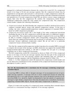
is a service platform, which is used for creating services. Figure 2.1 shows the very high
level organization of the UMTS network.
The network supports two types of access networks, namely, the Base-station System
(BSS) and the Radio Network Subsystem (RNS). BSS is the GSM access network, whereas
RNS is based on UMTS, in particular the Wideband Code Division Multiple Access (W-
CDMA) radio link. The Radio Access Network RAN specifications in Release 99 only
include UMTS Radio Access Network (UTRAN), but allude to other alternative radio
access networks. However, later releases have standardized a GSM/EDGE-based RAN,
called GERAN.
22 THE ALL-IP NEXT-GENERATION NETWORK ARCHITECTURE
Table 2.1 Evolution of 3GPP specifications
3GPP Freeze Date Highlights
Release
3GPP-R99 2000 Creation of UTRAN both in FDD and TDD
CAMEL phase 3
Location services (LCS)
New codec introduced (narrowband AMR)
3GPP-R4 2001 GERAN concept established
Separation of MSC into a MSC server and media gateway for
bearer independent CS domain
Streaming media introduced
Multimedia messaging
3GPP-R5 March– Introduction of IMS; IPv6 introduced in the
June 2002 PS domain
IP transport in UTRAN
Introduction of high-speed downlink packet access (HSDPA)
Introduction of new codec (wideband AMR)
CAMEL phase 4
OSA enhancements
3GPP-R6 Expected Multiple input, multiple output antennas
(expected March 2004 IMS stage 2
features) WLAN-UMTS interworking
MBMS
HSS
CS
Domain
BSS / RNS
Core
Network
Access
Network
NMS
Applications and Services
PS
Domain
IMS
Applications
& Service
MS
BSS Base Station System
CS Circuit Switched
HSS Home Subscriber Servers
IMS Internet Multimedia Subsystem
MS Mobile Station
NMS Network Management Subsystem
PS Packet Switched
RNS Radio Network Subsystem
Figure 2.1 High-level architecture of UMTS network
THE ALL-IP NEXT-GENERATION NETWORK ARCHITECTURE 23
While both types of AN provide basic radio access capabilities, UMTS provides higher
bandwidth over the air interface and provides better handoff mechanisms, such as soft
handover for circuit-switched bearer channels.
The CN primarily consists of a circuit-switched (CS) domain and a packet-switched
(PS) domain. These two domains differ in how they handle user data. The CS domain
offers dedicated circuit-switched paths for user traffic and is typically used for real-time and
conversational services, such as voice and video conferencing. The PS domain, on the other
hand, is intended for end-to-end packet data applications, such as file transfers, Internet
browsing, and e-mail.
3GPP-R5 also includes the IP Multimedia Subsystem (IMS). Its function is to provide
IP multimedia services, including real-time services, in the PS domain, including those that
were previously only possible in the CS domain. A CN based on 3GPP-R5 can contain a
CS domain, PS domain, IMS on PS domain, or a combination of these.
In addition, the core network has a logical function called the Home Subscriber Server
(HSS) that consists of different databases required for the 3G systems, including the Home
Location Register (HLR), Domain Name Service (DNS), and subscription and security
information. It also provides necessary support to different applications and services running
on the network. Network management is provided by the Network Management Subsystem
(NMS), which essentially forms a separate vertical plane.
Figure 2.2 presents a more detailed view of the network architecture. A brief description
of different subsystems follows, starting from the mobile station (MS), shown at the bottom
of the figure. For full details, please refer to the specification (3GPP 1999b) and references
therein.
The user’s terminal is called a mobile station (MS) and logically consists of mobile
equipment (ME) and an identity module. The ME consists of equipment for radio com-
munication, while the identity module contains information about the user identity. The
separation of MS and identity module achieves separation of the user and the device that,
in principle, allows a user to switch to a different device by merely plugging in an iden-
tity module. The network supports two types of identity modules, the Subscriber Identity
Module (SIM), similar to GSM systems, and the UMTS SIM (USIM), based on whether
the station belongs to the older GSM-based system or to the newer UMTS-based system.
The RNS consists of a radio network controller (RNC) that controls radio resources
in the access network. The RNC performs processing related to macrodiversity, and pro-
vides soft-handoff capability. Each RNC covers several Node Bs. A Node B is a logical
entity that is essentially equivalent to a base-station transceiver; it is controlled by the
RNC and provides physical radio-link connection between the ME and the RNC. Similarly,
the BSS consists of a Base-station Controller that controls one or more Base Transceiver
Stations; however, unlike the Node B, each corresponds to one cell. The IuCS and IuPS
interfaces connect all mobiles in the access network to the CS and PS domains of the CN
respectively.
The CS domain contains the switching centers (the Gateway Mobile Switching Center
or GMSC and the Mobile Switching Center or MSC) that connect the mobile network and
the fixed-line networks. These are analogous to exchanges in the PSTN, except that the
MSC also stores the current location area of the MS within a location register called visited
location register (VLR). The MSC also implements procedures related to handover between
the access networks, that is, when the ME moves from the coverage area of a RNC to another
24 THE ALL-IP NEXT-GENERATION NETWORK ARCHITECTURE
Figure 2.2 Basic PLMN configuration
THE ALL-IP NEXT-GENERATION NETWORK ARCHITECTURE 25
or from one BSC to another. With the Release 4 and Release 5 networks, the MSC function is
split between a circuit-switched media gateway (CS-MGW) and an MSC server, as shown in
Figure 2.2. The MGW handles user traffic, whereas the MSC server deals with location and
handover signaling. This separation makes the core network somewhat independent of the
bearer technology. It is similar to the Next-generation Network (NGN) architecture based on
a Softswitch (also known as a Call Agent) developed for fixed networks (3GPP 2000c). The
gateway MSC (GMSC) in the core network is similar in function to the MSC, except that it
is logically situated at the border between the mobile network and the external networks and
acts as a gateway. The GMSC relies on the HLR for location management, whereas the other
MSCs are internal to the network and rely on VLRs that are often collocated with the MSC.
The PS domain provides the General Packet Radio Service (GPRS). The PS domain
consists of the GPRS support nodes, which are counterparts to the MSC in the CS domain;
they maintain the subscription and location information for the mobile stations and handle
the user’s packet traffic and the PS domain-related signaling. There are two types of GPRS
support nodes: the Gateway GPRS Support Node (GGSN) and the Serving GPRS Support
Node (SGSN). These are analogous to the GMSC and MSC. The GGSN and the SGSN are
sometimes collectively referred to as GSN or xGSN.
For the purposes of location management, the PLMN is divided into several areas of
varying scope. The PLMN maintains the location of the mobile node for the purpose of
reachability in terms of several location regions (see Figure 2.3). The first of these are the
location areas (LA), which are used for locating the user for CS traffic; each is served by a
VLR, and a VLR may serve several LA. The routing areas (RA) are used for locating the
user for PS traffic; one or more RAs are managed by a SSGN. The UTRAN Registration
Area (URA) are smaller than the RA, and cells are the smallest unit of location. Typically,
a URA contains the cells controlled by a single RNC. An RA and LA may contain one or
more URA. An LA may contain more than one RA, but not vice versa.
The SGSN handles the user’s data traffic, including functions such as initial authen-
tication and authorization, admission control, charging and data collection, radio resource
management, packet bearer creation and maintenance, address mapping and translation, rout-
ing and mobility management (within its serving area), packet compression, and ciphering
for transmission over the RAN.
The association information between the PS core network and the MS for an active
packet session is encapsulated in a Packet Data Protocol (PDP) context, which contains the
information necessary to perform the SGSN functions. It includes information about the type
of packet data protocol used, associated addresses, addresses of upstream GGSNs, and the
identifiers to lower layer data convergence protocols in the form of access point identifiers,
NSAPI and SAPI, to route the packets to and from the access network. Figure 2.4 contains
a diagram of the PDP context.
The GGSN is often located at the edge of the PS domain and handles the packet
data traffic to the UMTS network from outside the network and vice versa. The GGSN
performs an important role in mobility management, packet routing, encapsulation, and
address translation. The most visible role for the GGSN is to redirect incoming traffic for a
mobile station to its current SGSN.
The GPRS Tunneling Protocol (GTP) is used for carrying traffic between the SGSN and
the GGSN. It carries control-plane information, such as commands to create, query, modify,
or delete the PDP context, as well as user-plane data.
26 THE ALL-IP NEXT-GENERATION NETWORK ARCHITECTURE
Location Area
Routing Area
VLR/
MSC
SGSN
Gs
Optional
GMSC
GGSN
HSS/
HLR
IuPS
Gn
Gc
Routing Area
UTRAN
Registration Area
RNC
UTRAN
Registration Area
RNC
UTRAN
Registration Area
RNC
UTRAN
Registration Area
RNC
C
Figure 2.3 A typical PLMN layout
There are a number of other entities and logical functions in the 3GPP architecture
that are not shown in Figure 2.2. These include the mobile location centers (MLC), num-
ber portability databases, security gateways, signaling gateways, and network management
entities and interfaces. While these are important functions, they are not part of the basic
transport and service network architecture, and hence are omitted here.
Figure 2.5 shows some components of the IP multimedia subsystem. The IMS provides
support for multimedia services, such as voice, video, and messaging over IP networks. IMS
uses the Session Initiation Protocol (SIP) for signaling. The Call State Control Function
(CSCF) has a role similar to the MSC in the CS domain. It terminates IMS signaling (SIP)
and provides call control functions. The IMS also contains media gateways that provide
interworking with legacy networks, such as the PSTN, and perform other resource-intensive
functions, such as mixing of media streams from multiparty conferences and transcoding.
Unlike the CS domain, the signaling entities (CSCF) are completely separate from the media
processing. The CSCF communicates with the Media Gateway Control Function (MGCF)
using SIP, and MGCF in turn controls the media gateways using ITU-T H.248
3
(ITU-T
2000b). The MGCF also provides necessary interworking with external networks in the
signaling plane.
Service Architecture
3GPP has adopted extensive specifications for services and service creation. This section
briefly summarizes the main concepts.
3
H.248 is also known as the Media Gateway Control (Megaco) Protocol (Groves et al. 2003)
THE ALL-IP NEXT-GENERATION NETWORK ARCHITECTURE 27
Type = 130 (decimal)
Length
FLAGS NSAPI
FLAGS SAPI
QoS Subscription, QoS Request
and Negotiated QoS Information
Sequence Numbers for Ordered
and/or Reliable Packet Transfer Function
between MS and SGSN
PDP Context Identifier
1 1 1 1 PDP Type Organization
PDP Type
PDP Address Length
PDP Address
GGSN Addresses for Control and Data Plane
APN Length
APN
Transaction Identifier
8 Bits
1 Octet
2 Octets
1 Octet
1 Octet
Variable
4 Octets
Tunnel Endpoint Identifiers (TEID) for Uplink Data
and Control Plane Traffic for the PDP Context
8 Octets
1 Octet
1 Octet
1 Octet
1 Octet
Variable
Variable
2 Octets
2 Octets
Figure 2.4 PDP context
Services in UMTS are viewed as having a layered structure as shown in Figure 2.6.
While several features of this diagram can be debated, the attempt at classifying services is
worthwhile. At the lowest level are bearer services, such as circuit-switched transport. Short
Message Service (SMS) (3GPP 1999c), Unstructured Supplementary Service Data (USSD)
(3GPP 1999e, 2000e,f), and User-to-User Signaling (UUS) (3GPP 1999f,g,h) are additional
bearer services that can be used by the applications to send different types of content.
Circuit teleservices operate in the CS domain and consist of simple telephone calls, fax,
and the like. Supplementary services also operate in the CS domain and provide enhance-
ments such as call waiting, call forwarding, and three-way calling. Non-call-related services
are those that do not directly relate to a call in progress, for example, notification that a
voicemail or e-mail message has arrived. Non-call-related value-added services are those
that do not relate to voice calls but offer, for example, advanced data capabilities such as
28 THE ALL-IP NEXT-GENERATION NETWORK ARCHITECTURE
Go
Cx
P-CSCF
CSCF
CSCF
MGCF
MGCF
MGW
MGW
Mw
Mn
Mg
MRFC
MRFC
Mr
Gm
(3GPP-SIP)
IP Networks PSTN
PSTN
MRFP
MRFP
Mp
Mb
MbMb
HSS
HSS
MS
MS
CSCF: Call State Control Function
HSS: Home Subscription Server
MGCF: Media Gateway Control Function
MGW: Media Gateway
MRFC: Media Resource Function Controller
MRFP: Media Resource Function Processor
P-CSCF: Proxy Call State Control Function
PDF: Policy Decision Function
SIP: Session Initiation Protocol
Signaling interface
User traffic interface
Figure 2.5 IP multimedia subsystem
Applications
& Service
CS
Domain
BSS / RNS
Core
Network
Access
Network
PS
Domain
IMS
MS
IP Multi-
media
Services
Other
bearers
Circuit
Tele-
services
Circuit Bearer
Services
GPRS
Value-added non-
call related
services
Supple-
mentary
Services
Figure 2.6 UMTS service classification
THE ALL-IP NEXT-GENERATION NETWORK ARCHITECTURE 29
e-mail access, web browsing, and file transfer. Finally, IP multimedia services are those that
deal directly with multimedia, for example image and video download and streaming.
It is important to point out that while 3GPP classifies services and provides an archi-
tecture and general requirements for services, the actual services themselves are not stan-
dardized. Instead, 3GPP standardizes service capabilities, which consist of generic bear-
ers – defined by Quality of Service (QoS) parameters such as bandwidth, delay, and sym-
metry – and the mechanisms needed to realize services, including the functionality provided
by various network elements, the communication between them, and the storage of associ-
ated data.
An overarching service concept in UMTS is the virtual home environment (VHE) (3GPP
2000h, 2002a). The basic idea of the VHE is that, as far as possible, users should have
available a consistent and personalized set of services and features as well as a consistent
user interface and “look and feel,” regardless of which network and which terminal they use.
To enable this, the VHE standards aim to provide mechanisms that allow uniform means
for accessing services, as well as a means for creating services.
VHE assumes that a user has a home environment, where one or more user profiles are
defined and stored. When a user moves outside this environment, the user profiles can be
utilized to provide a “virtual home environment” in the visited network.
Along with the generic bearers (defined by QoS), VHE is enabled by the user profile,
referred to as call control (CS, PS, or IMS control), and a collection of service tool-
kits. The service toolkits are essentially specifications of protocols, environments, or APIs
for developing services of various types. They include the User SIM Application Toolkit
(USAT) (3GPP 2000g), the Mobile Execution Environment (MExE) (3GPP 1999a) (3GPP
2000c), Customized Applications for Mobile Network Enhanced Logic (CAMEL) (3GPP
2000b) (3GPP 2000a), and Open Service Access (OSA). We discuss these toolkits briefly
in the rest of this section. 3GPP envisions that new toolkits can be added to the 3GPP
specifications, and non-3GPP toolkits can be used as required to satisfy the VHE concept.
CAMEL
CAMEL is used to provide network intelligence in the UMTS and is based on the IN con-
ceptual model of separation of high-level services from basic switching and call processing.
Unlike fixed networks, for which the IN concept was first developed, in mobile networks, the
subscriber can roam between switching centers and foreign networks, and CAMEL allows
the switching functions in the foreign network to interact with the service control functions
in the user’s home network. In a manner analogous to traditional IN services, a CAMEL
service residing in the service control function is invoked when a trigger contained in the
switching function fires.
CAMEL operates using two protocols: the CAMEL Applications Part (CAP) and the
Mobile Applications Part (MAP). The former is similar to the Intelligent Networks Appli-
cation Part (INAP) protocol in fixed networks and the latter is used for signaling between
the mobility service functions, such as the MSC or VLR, and the control function, such as
the HLR.
The functional architecture for call control with CAMEL is shown in Figure 2.7 and is
summarized briefly here.
There are three logical networks that interact to provide service. The first is the Home
Network of the user, which contains two logical entities, as in 2G cellular networks: the
30 THE ALL-IP NEXT-GENERATION NETWORK ARCHITECTURE
GMSC
GMSC
gsmSSF
gsmSSF
MSC
MSC
gsmSSF
gsmSSF
VLR
HLR
gsmSCF
gsmSCF
gsmSRF
gsmSRF
CAP
CAP
CAP
MAP
MAP
MAP
Forwarded Leg Outgoing Call or Forwarding Leg
Interrogating
Network
Home
Network
Visited
Network
Incoming
Leg
MS
MAP
Home, Visited or Interrogating
Network
Figure 2.7 CAMEL architecture
HLR, and the execution environment for services, here called the GSM Service Control
Function (gsmSCF). The latter is analogous to the service control proxy (SCP) in a fixed
IN network. The HLR stores the subscriber’s location and service profile information, here
called the CAMEL Subscription Information (CSI), and the gsmSCF stores the service
logic.
The second logical network is the Visited Network, where the user is currently located,
which contains three logical entities: the MSC, VLR, and a functional entity called the GSM
Service Switching Function (gsmSSF) that interfaces between the MSC and the gsmSCF.
The gsmSSF is analogous to the Service Switching Point (SSP) in a fixed IN network, and
the MSC and VLR are essentially as in a 2G cellular network.
The third logical network is the Interrogating Network, that is, the network that needs
information in order to provide a service to the user. This contains two logical entities: the
GMSC, and a gsmSSF to allow the GMSC to communicate with the gsmSCF. An example
of the information the interrogating network needs is the mobile user’s location from the
HLR in order to deliver a call. Unless the network supports “optimal routing” (3GPP 2000d),
that is, routing of calls directly to and from a user’s location without first visiting the Home
network, the Home Network will always be the interrogating network.
The gsmSRF shown in the CAMEL functional figure corresponds to the IN Intelligent
Peripheral, and can play announcements, collect user digits, and the like.
A representative (and highly successful) example of a CAMEL service is wireless pre-
paid service, where the subscriber establishes an account with the service provider and pays
before use in order to obtain service in home and visited networks. When the mobile user
initiates a call, the MSC recognizes the user as a prepaid subscriber; a preprovisioned trigger
at the originating MSC (and logically in the gsmSSF function) fires. The gsmSSF queries
the gsmSCF to validate the user, for example, to check if the user has sufficient funds. This
THE ALL-IP NEXT-GENERATION NETWORK ARCHITECTURE 31
query consists of a CAP message. If the gsmSSF gives an affirmative response, call handling
proceeds as usual, with real-time rating of the call started when the called party answers.
MExE
The MExE is the execution environment in the mobile terminal. The MExE client on the
terminal interacts with a MExE Service Environment (MSE) in the fixed network to deliver
services to the user. Two MExE devices can also, in principle, interact to provide a service.
3GPP assumes that a wide variety of terminal devices will be available and hence
defines categories of devices that are assigned into categories, called classmarks, based on
computational capability.
• Classmark 1 is a device that essentially supports WAP and has limited input and
output facilities.
• Classmark 2 is a PersonalJava
4
device with the addition of the JavaPhone API
5
.
PersonalJava supports web content access and Java applets, while the JavaPhone API
allows telephony control, messaging, and personal information management functions,
such as address book and calendar.
• Classmark 3 is based on the J2ME Connected Limited Device Configuration (CLDC)
6
and Mobile Information Device Profile (MIDP) environments
7
.
• Classmark 4 is based on the Common Language Infrastructure (CLI) Compact Pro-
file (Ecma 2002).
As an example, Figure 2.8 shows the APIs for Classmark 2 (3GPP 2000c).
Additional (Optional) Java Classes
Mandatory PersonalJava API
Implementation
Optional PersonalJava API
Implementation
Mandatory JavaPhone
API Implementation
Optional JavaPhone
API Implementation
MExE Application
Personal Java API
JavaPhone API
MExE API
Figure 2.8 MExE API for the Personal Java and JavaPhone environments
4
See for details about the Personal Java Application Environment
5
See for more information
6
See for more information
7
See for more information
32 THE ALL-IP NEXT-GENERATION NETWORK ARCHITECTURE
Services can be downloaded from the MSE to the terminal’s MExE. The MSE may
contain proxy servers to translate content to make it suitable for delivery on the mobile
terminal. All MExE devices are required to support capability negotiation, which usually
takes place before service commences. MExE can thus inform the MSE of the mechanisms,
resources, and support it can offer, using Composite Capability/Preference Profiles (CC/PP)
(W3C 2004); the MSE may inform the MExE which capabilities it is using or will use. MExE
devices may also engage in content negotiation with the MSE, using Hypertext Transport
Protocol (HTTP) or the Wireless Session Protocol (WSP), to determine the requested and
available form of content. Finally, the MExE can support one or more user profiles, storing
them in the ME or USIM.
USAT
In 3GPP terminology, a universal integrated circuit card (UICC) is defined as a physically
secure device, like an IC card (or “smart card”) that can be inserted into terminals. It
contains the subscriber identity module (SIM) used in 2G systems, or the universal SIM
(USIM) used in UMTS systems, for accessing mobile services. The first SIMs, introduced
in the late 1980s, had 4-bit CPUs and held about 10 kb of total memory for the OS and
user data; now SIMs with 512 kb memory and the compute power of 16-bit processors are
being planned (see, for example, ). The USIM thus goes beyond
the main initial functions of the GSM SIM, which were to store the mobile user’s identity
and personal information securely. It can essentially act as an execution environment in its
own right, with the ability to utilize certain functions of the ME.
The Universal SIM Application Toolkit (USAT) (3GPP 2000g) is an enhancement of
the SAT defined for 2G systems. It provides mechanisms to allow applications on the USIM
to interact with the ME, the user, and USAT servers in the fixed network. Among the
mechanisms provided are:
Profile download: Allows the ME to tell the USIM what functions it is capable of.
Proactive UICC: Allows the application to initiate actions to be taken by the terminal,
such as displaying text or playing tones from the USIM to the terminal, sending an
SMS, setting up a data or voice call, retrieving data from the ME, or initiating a
dialogue with the user.
Data download: Allows the service provider to download information to the USIM, such
as via SMS or cell broadcast.
Call control: Allows the application to intervene when the ME sets up a call, in a manner
analogous to how the IN SCP intervenes in PSTN calls. The ME passes all dialed
digits and relevant control strings and parameters to the USIM, as well as the current
serving ID. The USIM application can allow, bar, or modify the call.
OSA
With OSA, 3GPP has adopted the Parlay service framework (Jain et al. 2004a) as the
service framework for 3G networks (3GPP 2000h). OSA enables applications to use network
functionality defined in terms of a set of logical Service Capability Features (SCFs) that are
THE ALL-IP NEXT-GENERATION NETWORK ARCHITECTURE 33
Call
Control
Call
Control
User
Interaction
User
Interaction
Mobility
Mobility
Terminal
Capabilities
Terminal
Capabilities
Charging
Charging
Other
SCF
Other
SCF
Registered Services
Framework
AuthC & AuthZ
AuthC & AuthZ
Discovery
Discovery
Svc Agreement
Svc Agreement
Access
Access
HSS
HSS
CSE
CSE
S-CSCF
S-CSCF
Other
Servers
Other
Servers
Network
Infrastructure
Mapping Protocols
and APIs
OSA
API
Applications
Figure 2.9 OSA architecture
accessed via a language-independent API. The SCFs are encapsulated as Service Capability
Servers (SCS). Like Parlay, OSA consists of three parts (see Figure 2.9):
Applications: This is a call control application for call forwarding, a virtual private network
(VPN) application, or a location-based service. Applications execute on application
servers.
Framework: Before an application can access the SCFs, it must utilize the framework to
be authenticated and discover the available SCFs. In Figure 2.9, AuthC and AuthZ
stand for authentication and authorization respectively.
SCS: These are abstractions of underlying network functionality. Examples are call control
and user location. The MExE and CAMEL are also abstractly regarded as SCS, so
that a single functionality, such as call control, may be distributed across multiple
SCS.
The basic operations between the application and the framework are authentication,
authorization, discovery, service agreement establishment, and access to SCFs. The basic
operation between the framework and the SCS is for the latter to register itself with the
framework to enable discovery by applications. And the basic operation between the applica-
tion and the SCS is for the application to issue OSA API commands, including commands to
perform service functions as well as to register to be notified of underlying network events,
such as call origination. Parlay/OSA is summarized further in Chapter 6 of this book.
2.2.2 CDMA2000
Network Architecture
The UMTS and CDMA2000 systems differ largely in how they handle packet-switched
traffic in the core network. The IP multimedia subsystem and the service platform for open
services for the CDMA2000 system are similar to the IMS and the service platform for
UMTS networks.
34 THE ALL-IP NEXT-GENERATION NETWORK ARCHITECTURE
BSC
BSC
BTS
BTS
BTS
BTS
BS
ME
ME
UIM
UIM
Ui
MS
Um
Abis
PDSN
PDSN
A
quarter
Pi
Pi
ISDN
PDN
Q F
B
A
A
ter
E
MSC
MSC
C
EIR
EIR
N
D
NPDF
NPDF
HLR
HLR
BC
AC
AC
H
E
V
M
2
MC
MC
OTAF
OTAF
VLR
VLR
M
1
M
3
SME
SME
IP
IP
SN
SN
T8
SCP
SCP
T5 T1 T6
N
T9 T2 T4
PSTN
DF
DF
CF
CF
CDGP
CDGP
CDRP
CDRP
IWF
IWF
CDRP
CDRP
CSC
CSC
IAP
d
e
I
K
CDI
S
Y
Di
WNE
J
Service
Nodes
Pi
AAA
AAA
HA
HA
Pi
PiE
12
PDE
PDE
MPC
MPC
E
2
ESME
ESME
PCF
PCF
A
quinter
Z
3
VMS
VMS
LPDE
LPDE
Circuit Switched
Domain
Packet Switched
Domain
Entities for support of
location services
Call data and
charging functions
CRDB
CRDB
E
11
E
2
E
9
Figure 2.10 CDMA2000 wireless network architecture
For the purposes of present discussion, Figure 2.10 depicts the standard CDMA2000
architecture diagram partitioned into different domains. Although the CDMA2000 archi-
tecture specification does not do so, such partitioning makes comparison with UMTS
easier.
This chapter does not consider the following domains:
(i) The traditional PSTN and cellular service architecture consisting of SCPs, Intelligent
Peripherals, and Service Nodes
(ii) Functions related to call data and charging information collection, such as the Call
Data Generation Point
(iii) The ISDN portions of the PSTN network and interfaces to it
(iv) The functions for support of location services
These domains, with the exception of the last, are not specific to the 3G cellular nature
of the system, and thus not of interest for architectural discussion; the last is fairly straight-
forward.
For the comparison with the UMTS network architecture, this discussion considers the
following two main domains: (1) the CS domain in the center of the figure that is identical
to the 2G circuit-switched cellular architecture, as it is for UMTS; and (2) the PS domain.
THE ALL-IP NEXT-GENERATION NETWORK ARCHITECTURE 35
From a high-level perspective, the CDMA2000 architecture thus has a CS domain and a PS
domain in a manner similar to UMTS. The CDMA2000 network also supports the IMS for
Internet multimedia services, and OSA for service creation, in a manner similar to UMTS.
Thus, the main difference between UMTS and CDMA2000 from this architectural per-
spective lies in the PS Domain. The latter consists of the packet control function (PCF),
packet data support node (PDSN), mobile endpoint home agent (HA), and an authentication,
authorization, and accounting (AAA) function. (PCF technically is a radio access network
function, but shown with the PS domain for convenience, and controls the transmission of
packets between the BSC and the PDSN.)
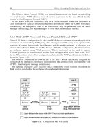
The access network diverts the packet-switched traffic to the PDSN. The PDSN termi-
nates the logical link control layer for all the packet data (refer to Figure 2.14 later in this
chapter) and additionally acts as the foreign agent or access router, depending on the net-
work configuration and whether the network uses IPv4 or IPv6 to support IP-based mobility
with Mobile IP (Johnson et al. 2004; Perkins 2002a). The PDSN also interfaces to the AAA
subsystem for performing AAA for packet access and with the HA and other PDSN to
support mobility using Mobile IP.
The services in the CS domain in the CDMA2000 architecture are based on the Wireless
Intelligent Network (WIN) (TR-45.2 1997, 2001) standards, which are similar in nature to
the GSM MAP and CAMEL architecture explained earlier. Figure 2.11 shows a simplified
configuration using WIN. Just as in CAMEL, the high-level services are moved away from
the MSC and implemented in a SCP. The MSC consults the HLR and the SCP during the
processing of the call, and the SCP or HLR decide what type of service to provide for a
particular call. This model simplifies the MSC and makes the service deployment somewhat
easier. The Intelligent Peripheral performs simple tasks such as collecting digits or speech-
to-text conversion and hands over the results to the SCP for further processing. The Service
Transfer Point (STP) is a packet switch (not shown, but resides in the SS7 network) that
connects the different components of the network.
Just as in UMTS, 3GPP2 is standardizing OSA and its mapping to the internal network
protocols, such as IS-41 and Wireless Intelligent Network Application Part, the 3GPP2
equivalent of MAP.
MSC
VLR
HLR
SCP
IP
SS7
Network
Figure 2.11 WIN components with stand-alone HLR
36 THE ALL-IP NEXT-GENERATION NETWORK ARCHITECTURE
Service Architecture
The service architecture for CDMA2000 system is similar to that of UMTS, as it relies on
the same underlying domains (CS and PS) and adopts the IMS for multimedia services.
3GPP2 also adopts the principles of the VHE, although in a slightly different form.
Thus, the key differences between the UMTS and CDMA2000 architectures are generally
found in the network architecture, and particularly in the air interface and RAN design. This
situation reflects the main concerns of 3G network designers. As we have mentioned, we
believe that, for XG networks, the key features and differentiators in fact will lie at the
service architecture levels, as 3G networks do not have such features today.
2.2.3 MWIF
Network Architecture
The MWIF was an industry forum formed in early 1999 by leading 3G operators, telecom-
munications equipment providers, and IP networking equipment providers to develop all-IP
network architectures for the core network and RAN as a counterpoint to the 3GPP R4 archi-
tecture. The MWIF core architecture is intended to completely eliminate circuit-switched
support except as a compatibility option through a gateway, and the MWIF RAN archi-
tecture is intended to support IP to the base station, instead of ATM as in 3GPP R4. In
2002, MWIF dissolved into the Open Mobile Alliance, which took up where MWIF left
off, focusing on the service architecture. This section discusses the MWIF core and RAN
architectures, with reference to 3GPP R5 for consistency with previous sections.
In comparison with the 3GPP R5 architecture, the MWIF design does not consider
the PSTN and focuses only on packet-switched transport. The MWIF architecture is based
entirely on Voice over IP after traffic leaves the access network; thus, there is neither an
IU-CS interface nor an MSC in the MWIF design. The MWIF core architecture consists
of two parts: a layered functional architecture (Barnes, M. 2000) (see Figure 2.12) and a
network reference architecture (Wilson, M. 2002) (see Figure 2.13).
The layered functional architecture has four layers and two cross-layer functional areas.
The four layers are:
Applications: This layer is specifically for third-party applications available through the
mobile operator’s network
Services: Applications within the operator’s network and such basic networking support
services as naming and directory services
Control: Mobility management, authorization, accounting, real-time media management,
network resource management, and address allocation
Transport: Basic IP routing, gateway services to access networks
The two cross-functional areas are:
• Operations, administration, management, and provisioning
• Security
THE ALL-IP NEXT-GENERATION NETWORK ARCHITECTURE 37
Access Gateway
Access Gateway
Access Network
Access Network
MGW
MGW
IP GW
IP GW
Sig GW
Sig GW
PSTN
PSTN
IP NW
IP NW
Sig NW
Sig NW
2G NW
2G NW
External
Networks
Transport Layer
Mobility Mgmt
Mobility Mgmt
Control Layer
Terminal
Terminal
Session Mgmt
Session Mgmt
Resource Mgmt
Resource Mgmt
Address Mgmt
Address Mgmt
Accounting
Accounting
Authentication
Authentication
Application
Services
Application
Services
Services Layer
Service
Name
Service
Name
Service
Location
Service
Location
Service
Authorization
Authorization
Policy
Server
Policy
Server
3
rd
Party
Applications
3
rd
Party
Applications
Applications Layer
API
API
API
OA&M
OA&M
Security
Security
Directory
Figure 2.12 MWIF layered functional architecture. Reproduced by permission of OMA
The layered functional architecture was developed into a network reference architecture
that assigns particular functional entities to specific network entities. The result is a design
for a core network with 68 specific network reference points that act as interfaces between the
network entities and outside networks. Where appropriate, MWIF has identified standardized
protocols from the suite of Internet standard protocols for each of these interfaces.
A separate effort within MWIF designed a functional architecture for a general radio
access network based on open, IP-based protocols, called OpenRAN (Kempf and Yegani
2002). The idea behind OpenRAN was to utilize IP-based signaling and transport for radio
access networks where possible instead of ATM and SS7, which are used in the 3G RAN
architectures. A feature of the OpenRAN is a separation of the control and data planes to
accommodate the expected difference in scalability properties of these two basic functions.
However, depending on the radio protocol, the two may merge on the radio layer.
The OpenRAN architecture consists of 14 functional entities separated by 27 reference
points. Two reference points connect the OpenRAN control and data planes to the MWIF
Access Network Gateway (and thus to the MWIF core network) and two connect the control
and data planes to another OpenRAN. Additional reference points are available to connect
with legacy circuit-switched networks. The baseline radio protocol for the OpenRAN was
CDMA, but other protocols could be accommodated by dropping particular functions specific
to CDMA. Like the 3G networks, OpenRAN does not provide voice over IP over the air, but
rather terminates voice over IP at a functional entity that adapts the IP traffic to the radio.
38 THE ALL-IP NEXT-GENERATION NETWORK ARCHITECTURE
Figure 2.13 MWIF network reference architecture. Reproduced by permission of OMA
THE ALL-IP NEXT-GENERATION NETWORK ARCHITECTURE 39
Service Architecture
A service architecture is not explicitly defined in MWIF. It is implicitly assumed that
telephony-oriented services can be developed with an end-to-end approach using SIP sig-
naling. However, an IMS similar to that for UMTS and CDMA2000 system can also, in
principle, be used; it can be connected directly to the IP core rather than to a PS domain.
The design of MWIF reflects the focus of 3G network architects and designers on
the RAN and core network. It also reflects a major goal, which is to obtain seamless
interoperability with the Internet by using IP as the core base protocol, which is certainly
desirable. As we observed in Section 2.2.2, we believe that for XG networks, the key
features and differentiators in fact will lie at the service architecture levels.
2.2.4 Limitations of 3G Architectures
The 3G architectures presented above have several architectural limitations. In terms of the
network architecture, UMTS in particular duplicates functionality for different traffic types,
has a complex protocol stack, and uses a modified SIP protocol that is relatively heavy
weight. In terms of service architecture, UMTS and CDMA2000 have a somewhat limited
programmability concept, and, while they offer several point solutions, they do not have a
coherent programmability solution.
This section briefly discusses the important limitations of the 3G architectures consid-
ering the network architecture (including logical separation of networking functions and
protocols) and the service architecture (including provision for developing and deploying
new services).
Network Architecture
The UMTS, CDMA2000, and MWIF architectures all suffer from various limitations, as
summarized here (see Table 2.2).
UMTS. The first fundamental characteristic of the UMTS architecture that becomes
obvious is the separation into three domains: CS, PS, and IMS, corresponding roughly
to voice, data, and packet-based multimedia services. This separation has the important
commercial virtue that it offers a relatively easy migration path from 2G to 3G, preserving
infrastructure investments, since the PS domain can be incrementally added to CS, and
IMS can be added after that. However, from a network architecture perspective, it has
the significant drawback that it entails duplication of functionality. At an abstract level, it
is undesirable that new types of network elements (SGSN, GGSN, etc.) be developed to
provide the same functionality (e.g., mobility management) for user traffic with different
QoS characteristics. It could be argued that the CS and PS would simply “wither away”
in time, leaving an IMS-only architecture (and, in principle, a greenfield operator could
choose to build an IMS-only network). However, the additional capital expense, as well as
the operational expense and complexity in the interim, is significant.
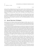
Another issue is the complexity of the transport protocol stack as shown in Figure 2.14
for packet data in the PS domain (Park 2002) in a typical UMTS network that uses an ATM
backbone to interconnect access and core network entities.
A user data packet moves up and down the stack several times before it is handed over
to an IP native network. This access network architecture not only has several points at
40 THE ALL-IP NEXT-GENERATION NETWORK ARCHITECTURE
Table 2.2 Summary of UMTS, CDMA2000, and MWIF network architecture limitations
UMTS CDMA2000 MWIF
Integration and Complex, due Complex, due to Simplest, in principle.
interoperability to separation of separation of However, specification
with the Internet domains, domains, protocol is not comprehensive
protocol stack and stack and other and system is not
other issues (see issues (see rows deployed (see rows
rows below) below) below)
Separate CS/PS Separate Similar to UMTS Unified handling for
domains PS/CS/IMS all traffic
domains
Protocol stack Complex stack Simpler stack for Simplest, all native
due to IP over packet data, IP stack
ATM, sequential removing some
tunneling, use stack traversals;
of GTP Mobile IP is used
for mobility
management
Routing Use of ATM Cost may be May be lowest due
equipment cost transport may lower than UMTS to economies of scale
raise cost compared if native IP of standard IP
to native IP is used solutions
Real-time packet Problematic due Not clear Not clear, as native
data services to modified SIP IP-based solutions
and other do not support QoS
latencies guarantees well
Coupling of AN Close dependence Close dependence Independence
and CN between AN and CN
specifications
Service VHE concept offers Similar to UMTS Not addressed
architecture and OSA, MExE, explicitly or
programmability USAT etc., but with in detail
limited, and not
comprehensive,
programmability
Commercial Several large-scale Widely Not deployed
deployment deployments deployed
THE ALL-IP NEXT-GENERATION NETWORK ARCHITECTURE 41
Path of User Data
3GPP interface
ATM
AAL2
wCDMA
Physical
Layer
Phy
ATM
AAL2
Phy
RLC-U
PDCP
MAC
ATM
AAL5
Phy
UDP
GTP-U
IP
ATM
AAL5
Phy
UDP
GTP-U
IP
ATM
AAL2
Phy
UDP
GTP-U
IP
L1
L2
RLC-U
PDCP
MAC
wCDMA
Physical
Layer
ATM
AAL2
Phy
ATM
AAL2
Phy
IPIP
MS
BTS Drifting-RNC Serving-RNC SGSN GGSN
Uu Iub Iur Iu-
PS
Gn
IP
Figure 2.14 Transport protocol stack for typical UMTS network deployment using ATM
backbone
which packet segmentation, reassembly, and retransmissions occur, leading to additional
delay, but it also adds unjustifiable complexity to the network.
The protocol stack uses GTP to tunnel data in the CN. Closer inspection of the protocol
stack shows that in fact there are two GTP tunnels involved: one between the GGSN and
the SGSN and another between the latter and the Serving-RNC. Tunneling is a problem
shared with the MWIF architecture as well as other all-IP architectures. However, setting
up two sequential tunnels is particularly undesirable because of the additional overhead.
The protocol stack further shows the use of ATM transport all the way from the BTS
to the GGSN, with IP over ATM AAL2 from the Serving-RNC to the GGSN. IP over
ATM has a number of issues, such as fixed ATM cell size leading to packet fragmentation,
virtual circuit setup delays, and need for interaction between ATM rate control and higher-
layer congestion control mechanisms. Native IP transport over a simple MAC protocol is
preferable. From a deployment perspective, market conditions may make the cost of ATM
infrastructure greater than using native IP as economies of scale may favor the latter (if
they do not do so already).
We observe that GTP is designed to be independent of underlying network protocols and
can carry a number of different packet data protocols, including X.25, Frame Relay, and IP,
transparently. While such a design is beneficial in principle, since many data protocols could
be accommodated easily, in practice, the immense growth and popularity of IP means that
GTP is used only to carry a single protocol. Its flexibility thus leads to needlessly adding
another protocol to the stack, and one that is not well-known outside the cellular networking
community.
The IMS in UMTS can support real-time services, and UMTS has used a significantly
modified version of SIP to do so. The modified SIP protocol aims to allow negotiation of
communication details (codecs, etc.), ensure network paths of the required QoS are available
before the session starts, and provide appropriate charging signaling to prevent service fraud
(Kim and Bohm 2003). In addition, the IMS works in conjunction with the PS domain, the
application platform, and other infrastructure entities, such as the gateways and subscription
servers. In principle, basic SIP session setup can be done using as few as 3 messages and
with 1.5 Round-trip Time (RTT) delay. Within the UMTS architecture, the modified protocol
can require as much as 30 messages exchanged between different network entities (3GPP
2001a). One important goal of the next-generation network is to eliminate such extraneous
interactions, while maintaining the desired security and QoS properties.
42 THE ALL-IP NEXT-GENERATION NETWORK ARCHITECTURE
cdma
2000
air
interface
cdma
2000
air
interface
PL
R-P
PPP
IP
PL
R-P
PPP
IP
PL
Link
Layer
IP
PL
Link
Layer
cdma
2000
air
interface
cdma
2000
air
interface
PL
R-P
PPP
IP
PL
R-P
PPP
IP
PL
Link
Layer
IP
PL
Link
Layer
PL
R-P
PL
R-P
Mobile Station Radio Network PDSN End Host
Mobile Station Radio Network new PDSN End Host
Old PDSN
P-P
Interface
Figure 2.15 Protocol model for IP packet data
CDMA2000 System. The CDMA2000 architecture does not suffer some of the more
obvious architectural problems of UMTS. In particular, the protocol stack for CDMA2000
system is shown in Figure 2.15; a data packet need not undergo multiple transformations
to reach the Internet. The top portion of the figure shows normal operation while the MS
is stationary. The PDSN uses the Point-to-Point Protocol (PPP) to maintain a link with the
mobile station and, in effect, this forms a link control layer. This scheme is much simpler
than the UMTS approach, because now there is only one logical link control connection
between the first hop IP router and the mobile station, and hence the protocol stack is
relatively simple.
A major difference in CDMA2000 system architecture is use of Mobile IP combined
with AAA functions to support handover, unlike the UMTS network where GTP com-
bined with MAP, used to communicate with the Authentication Center, is used for mobility
management.
The CDMA2000 system also introduces an edge-based technique for handoff in PS
domain, by stretching the PPP tunnel between the old and the new Packet Control Function.
This technique is sometimes referred to as “stretchy PPP” and effectively defers the signaling
and end-to-end path update between the MS and its correspondent nodes, handling mobility
locally. This scheme is similar in spirit to the fast mobile IP techniques, which are discussed
later in this book, and is fairly effective in reducing packet loss during the handover.
MWIF. To a large extent, MWIF is the 3G architecture that comes closest to the basis
for an XG architecture. The elimination of a CS domain in the core, with an emphasis