Next Generation Mobile Systems 3G and Beyond phần 4 ppsx
Bạn đang xem bản rút gọn của tài liệu. Xem và tải ngay bản đầy đủ của tài liệu tại đây (610.67 KB, 41 trang )
100 WIRELESS LAN EVOLUTION
communication medium. In contrast to the CSMA/CD protocol used in Ethernet, where
collision detection can be easily realized, the CSMA/CA protocol (developed for an 802.11
wireless network) makes an effort to avoid collisions, because the wireless receiver has
difficulty with collision detection. The receiver uses the following features and functions:
• Adaptive collision window (CW) based random backoff time to reduce the probability
of collisions
• Different interframe space (IFS) to prioritize different types of transmissions
• Acknowledgement frame to realize the stop and wait ARQ
• Request to send (RTS) and clear to send (CTS) handshaking to solve the hidden
terminal problem
• Network Allocation Vectors (NAV) to realize virtual carrier sense
As in other random access protocols, the random backoff time in CSMA/CA works to
avoid collisions between transmissions from different STAs. The random backoff time can
be calculated from this equation:
Backoff
time
= Random() ∗ Slot
time
(4.1)
In this equation, Random() = [0, CW], (CW
min
≤ CW ≤ CW
max
),andSlot
time
is the
value of the corresponding PHY characteristic. Suggested values are CW
min
= 31 and
CW
max
= 255. If it is the current packet’s first transmission, CW is set to CW
min
.After
each collision of this packet, the collision avoidance mechanism doubles CW until it reaches
CW
max
.
CW
new
= (CW
old
+ 1) ∗ PF − 1 (4.2)
In this equation, PF is equal to 2. This is referred to as the exponential backoff algorithm.
The offered load to the channel is high when experiencing a collision, so increasing the CW
to increase the backoff time of each colliding STA helps decrease the collision probability.
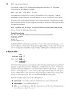
The IFS is a time interval after a busy state of the channel. This interval plays an
important role in CSMA/CA for collision avoidance and prioritized transmissions. The IFS
requires an STA to wait for a period of time after it senses the idle state of the channel.
Then, the STA waits for a random backoff time before transmitting its frame. There are
four basic types of IFS:
• Short IFS (SIFS)
• Point IFS (PIFS)
• Distributed IFS (DIFS)
• Extended IFS (EIFS)
Each type has a distinct interval time. The four types are designed for transmitting
different types of frames. SIFS is used to transmit frames with the highest priority, such
as acknowledgment (ACK), CTS, and poll response. PIFS is used in the point coordinate
WIRELESS LAN EVOLUTION 101
function when an AP issues poll frames. DIFS is used by ordinary asynchronous traffic. EIFS
is used when a MAC frame is received with an error. Some examples of IFS relationships
are shown in Figure 4.8.
A stop-and-wait ARQ is combined with CSMA/CA. An ACK frame is sent by the STA
that successfully receives a data frame. An SIFS is used for sending an ACK frame to
guarantee the highest transmission priority.
There is a well-known hidden terminal problem in CSMA-type protocols. RTS-CTS
handshaking is used to solve this problem. Accordingly, the concept of network allocation
vector (NAV) is introduced. Figure 4.9 shows the time chart of the CSMA/CA with RTS-
CTS handshaking.
The source STA sends an RTS to the nearby STAs to make a reservation and start a
NAV period. The destination STA sends a CTS to respond to the reservation and start a
SIFS
PIFS
DIFS
DIFS
Busy
Medium
Defer Access
Contention Window
Backoff Slots
Slot Time
Select Slot and Decrement Backoff as long as medium is idle
Next Frame
Immediate access when
Medium is free >=DIFS
Figure 4.8 Some IFS relationships
RTS
DIFS
CTS
SIFS
SIFS
Data
NAV (RTS)
ACK
SIFS
DIFS
NAV (CTS)
Defer Access Backoff
Contention
Window
Sender
STA
Destination
STA
Other
STA
NAV
Set
Figure 4.9 IEEE 802.11 MAC RTS-CTS handshaking
102 WIRELESS LAN EVOLUTION
NAV period for neighboring STAs. NAV protects the current transmission, thus solving the
hidden terminal problem.
4.2.2 PHY Technologies
The four IEEE 802.11 PHY standards are listed in Table 4.2. The fifth is being developed
in IEEE 802.11 TGn, targeting a new PHY to support a throughput of more than 100 Mbps.
This section briefly introduces the OFDM-based PHY technologies in 802.11, known as
802.11a and 802.11g.
As described in Chapter 3, the multicarrier transmission is an efficient scheme for solv-
ing the problem of severe frequency-selective fading in broadband wireless access systems.
Figure 4.10 depicts such a mechanism. After experiencing a multipath propagation, an
impulse waveform at the transmitter becomes widely spread in the time domain at the
receiver. This results in intersymbol interference (ISI) in digital communications. When the
symbol rate is low, the problem of ISI can be solved by using an equalizer or canceler at the
receiver. The higher the symbol rate, the more complex the equalizer/canceler. This is one
of the fundamental problems of broadband wireless access. One solution is a multicarrier
transmission that can reduce the symbol rate at each subcarrier, so narrowband solutions
can be used in this situation. OFDM is one of the most spectrum-efficient multicarrier
transmission methods.
Figure 4.11 shows a block diagram of OFDM transceiver. A channel-encoded data
stream is input for the transmitter. The serial data stream is first transformed into paral-
lel and then modulated separately. An Inverse Fast Fourier Transform (IFFT) is used as
Direct path
Path 1
Path 2
time
Transmitting Waveform
(impulse shape)
time
Combination of
direct wave and
delayed waves
Receiving
Waveform
Multipath
propagation
in time domain
multipath
time
Transmitting
waveform
frequency
time
Avoid ISI
Receiving
waveform
frequency
Multi-carrier
Solution (OFDM)
Figure 4.10 Multicarrier transmission in a multipath propagation environment
WIRELESS LAN EVOLUTION 103
Coded
Data
S/P
Trans-
form
…
…
modulation
IFFT P/S
Insert
GI
…
OFDM
amplitude
frequency
…
TX
Decoded
Data
P/S
Trans-
form
Symbol
Sync
Carrier
Frequency
Compen-
sation
S/P
Delete
GI
RX
FFT
…
…
subcarrier
detection
Figure 4.11 OFDM transceiver block diagram
the processing algorithm to create OFDM symbols. To keep the subcarriers orthogonal in a
multipath propagation environment, a guard interval (GI) is inserted in each OFDM symbol.
After a parallel-to-serial transform, the OFDM symbols are transmitted. The figure shows
that the subcarriers overlap each other. These overlapped carriers do not interfere with each
other, improving the spectrum utilization efficiency. At the receiver, the GI is deleted and
the FFT is used as the algorithm to transform OFDM symbols from a frequency domain
into a time domain.
Figure 4.12 shows an important mechanism that uses a GI to reduce multipath effect in
OFDM communications. After multipath propagation, the received waveform may involve
the direct wave as well as delayed wave components. If there are no means of protection,
these components will exist in the results of FFT, that is, each parallel signal stream. The
GI is designed to reduce the effect caused by delay spreads. As shown in Figure 4.11, the
GI is generated by copying the bottom parts of OFDM symbol and inserting them into the
top parts. The multipath effect of the GI is shown in Figure 4.12. The ISI effect can be
reduced if the delayed waves arrive at the receiver within the window of GI.
Table 4.2 shows the parameters related to OFDM in 802.11 standards. A 52-subcarrier
OFDM symbol consists of 48 subcarriers for information and 4 subcarriers for pilot. Pilot
is a known signal sequence to detect and compensate for frequency synchronization errors.
The transmission rate varies from 6 to 54 Mbps, according to different modulation schemes
and coding rates used. The GI is 800 ns, enabling the WLAN to work in a multipath
environment with a root mean square (RMS) delay spread of 100 to 200 ns. Each of the
subcarriers is spaced 312.5 kHz apart and the GI is added to each symbol to make the total
symbol duration 4 s.
104 WIRELESS LAN EVOLUTION
Cyclic extension
Subcarrier
f1
f2
f3
f4
Direct path
signal
Multi path
delayed signals
GI
DataGI
Data GI Data
Timing ISI
Optimum
Early
Late
Small ISI
Large ISI
Optimum FFT window
Early FFT window
Late FFT window
Figure 4.12 Reduction of multipath effect using OFDM
Table 4.2 IEEE 802.11a parameters
Parameter Value
Data rate 6, 9, 12, 18, 24, 36, 48, 54 Mbps
Modulation OFDM with BPSK, QPSK, 16-QAM, 64-QAM
Number of subcarriers 52 subcarriers including 4 for pilot
64 point FFT
FEC Convolution coding with K=7, R=1/2, 2/3, 3/4
Viterbi decoding
Interleaving within an OFDM symbol
OFDM symbol duration 4 s
Guard interval 800 ns
Subcarrier spacing 312.5 kHz
-3 dB bandwidth 16.56 MHz
Channel spacing 20 MHz
Figure 4.13 shows the PHY frame format of 802.11g. For backward compatibility, the
Physical Layer Convergence Protocol (PLCP) preamble and header are the same in both
802.11 and 802.11b. The Physical Service Data Unit (PSDU) uses OFDM and has the
same structure as in 802.11a. Depending on the 48-subcarrier BPSK, QPSK, 16-QAM, and
64-QAM, the raw data rate can reach to 12–72 Mbps. In order to reduce the effect of fading,
WIRELESS LAN EVOLUTION 105
SYNC
(128bits-
Scrambled
Ones)
SFD
(16 bits)
Signal
(8 bits)
Service
(8 bits)
Length
(16 bits)
CRC
(16 bits)
OFDM
Sync
(Long
Sync
– 8 us)
OFDM
Signal
Field
(4 us)
OFDM
Data
Symbols
OFDM
Signal
Extension
(6us)
PLCP
Preamble
(144 bits)
PLCP Header
(48 bits)
PSDU
(Data Modulation)
PPDU
DBPSK
Modulation
DBPSK
Modulation
OFDM
Modulation
Figure 4.13 IEEE 802.11g PHY frame format
the convolutionary channel coding with a rate of 1/2 and soft-decision Viterbi decoding is
specified.
Although 802.11g takes advantage of both 2.4 GHz and OFDM technologies, its per-
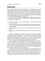
formance is not as high as expected. Figure 4.14 shows the upper limits of throughput for
802.11a/b/g (Morikura and Matsue 2001). Note that the throughput of CCK-OFDM does
not increase significantly as the PHY layer transmission rate increases. The main reason for
this is the relatively long PCLP preamble and header.
4.3 Evolution of WLAN
WLAN has become increasingly popular over the past few years, and customers are demand-
ing additional functionality. To provide high-speed Internet access in a public-access sce-
nario, a WLAN must make an optimal trade-off between bit rates and range. In the home
environment, significant challenges include the simultaneous distribution of high-definition
video, high -speed Internet, and telephony. Such applications demand efficiency, robustness,
and QoS from the WLAN. The forthcoming WLAN system is expected to provide a variety
of services not currently available, such as:
• Higher data rates (more than 100 Mbps) and low power consumption
• Extended coverage areas and scalability using the multihop/mesh network
• Coexistence of heterogeneous access devices in the same environment
106 WIRELESS LAN EVOLUTION
0
5
10
15
20
25
30
35
0 6 12 18 24 30 36 42 48 54
PHY Rate [Mbit/sec.]
IP Throughput [Mbit/sec.]
802.11a
CCK-OFDM
(short)
CCK-OFDM
(long)
ă802.11b (short)
ă802.11b (long)
Figure 4.14 The maximum IP throughput. Reproduced by permission of Dr. Morikura
• Seamless mobility support:
– Handoff mechanism and seamless AAA during handoff
– Interworking with other systems, seamless mobility between various access tech-
nologies, allowing continuity of existing sessions
• Differentiated service support for differing reliability needs
• Indoor location estimation
• Quality of service assurance, including support of real-time applications
• Enhanced security features, including authentication/authorization and data cipher
A number of the issues that limit current WLAN services can be addressed through
new technologies. This chapter focuses on the WLAN issues that will be most urgently
needed to create solutions complementary to XG mobile networks. The following sections
discuss in more detail the technologies related to mobility support, QoS, and enhanced
security.
WIRELESS LAN EVOLUTION 107
4.3.1 Higher Data Rates and Low Power Consumption
Typical office applications, such as the downloading of large e-mail attachments, are data
intensive. In a public hotspot, such as a hotel or airport, the time available for download is
likely to be limited. A public wireless access solution should ideally be able to offer very
fast transmission capacity.
Both simulation and experience have shown that the throughput in an 802.11a network
is actually limited to a point significantly below the 54 Mbps theoretically achievable by
the PHY layer. There is also a theoretical maximum throughput for 802.11 MAC (Xia
and Rosdahl 2002; Xiao and Rosdahl 2002). However, a WLAN that uses the CSMA/CA
mechanism employs four different interframe spaces (IFSs) to control access to the wireless
medium. These IFSs act as overhead, which limits the improvement of throughput perfor-
mance. To reduce this MAC overhead, new systems may use multiple antennas solutions,
bandwidth increment, turbo codes, and higher-order constellations, all of which can help to
increase the theoretically achievable capacity (Simoens et al. 2003).
The TGn of IEEE 802.11WG is now working on improving the current MAC and
PHY throughput. The next generation of WLAN should be able to improve throughput
performance significantly, with data rates of more than 100 Mbps.
However, much of the research that targets maximum throughput does not consider
increased power consumption. Energy efficiency is becoming crucial to the design of next-
generation wireless systems, especially for WLAN that is used by mobile devices with
limited battery life. Although WLAN does include a power-management scheme, further
power efficiency from both PHY and MAC solutions will be needed.
4.3.2 Extended Coverage Areas and Scalability
Multihop mesh network communication is gaining popularity, both for pure ad hoc commu-
nication networks and for coverage extension in wireless networks. A mesh network differs
from an ad hoc network in that each WLAN node operates not only as a host but also as
a router. User packets are forwarded to and from an Internet-connected gateway in mul-
tihop fashion. The network is dynamically self-organizing and self-configuring; the nodes
in the network automatically establish and maintain routes among themselves. This makes
the meshed topology reliable and it provides good area coverage. Systems are scalable and
initial investment can be minimal because the technology can be installed incrementally,
one node at a time, as needed. As more nodes are installed, both reliability and network
coverage increase (Fitzek et al. 2003; Jun and Sichitiu 2003). This option would decrease
installation costs for WLAN hotspots of the next generation.
A mesh network’s traffic pattern is different from that of an ad hoc network. In the
mesh network, most traffic is either to or from a gateway, while in ad hoc networks, the
traffic flows between arbitrary pairs of nodes. Because of poor support for multihop opera-
tions in the current IEEE 802.11 standard, current WLAN systems show poor performance
for such multihop/mesh networks. To improve this, we need to find more-efficient MAC
schemes that make it possible to operate these devices in multihop mode without exces-
sive performance degradation. In the IEEE 802.11 WG, a Mesh Network Study Group
was approved to be a TG in March 2004 to create a new standard for mesh networks
over WLAN.
108 WIRELESS LAN EVOLUTION
4.3.3 Coexistence of Access Devices
The WLAN operates in the 2.4-GHz industrial, scientific, and medical (ISM) unlicensed
band. In the unlicensed ISM band, frequencies must be shared and potential interference
tolerated as defined in Federal Regulations Part 15 of Federal Communications Commis-
sion (FCC). Spread spectrum and power rules are fairly effective in dealing with multiple
users in the band as long as the radios are physically separated, but not when the radios are
in close proximity. This would be a problem for IEEE 802.11 WLAN and Bluetooth that,
for example, come together in a laptop or desktop.
To operate in the 5-GHz range, WLAN must share with other systems, such as military,
aeronautical, naval RADARs, and satellite systems. In Europe, for example, WLAN oper-
ating on the 5 GHz band is required to implement dynamic frequency selection (DFS) and
transmit power control (TPC) in order to share with radar systems.
Current research is focused on the coexistence of wireless devices in the 2.4-GHz band
and other bands.
• The IEEE 802.15.2 standard specifically addresses coexistence between WLAN and
Bluetooth systems. This standard has adopted an adaptive frequency hopping (AFH)
mechanism, which modifies the Bluetooth frequency hopping sequence in the presence
of WLAN direct sequence spectrum devices (Golmie 2003; Golmie et al. 2003).
• The TGh standard in the IEEE 802.11 WG met the European regulatory requirement
for coexistence with radar systems.
• The IEEE 802.19 Coexistence Technical Advisory Group (WG19) is working on
policies that define the responsibilities of 802 standards developers to address issues
of coexistence with existing standards and other standards under development.
4.3.4 Seamless Mobility Support
Smooth on-line access to corporate data services in hot spots should allow users to move
freely from a private, microcell network to a wide-area cellular (3G) network. In the next
generation, various complementary RANs, including WLAN, will be used in combination
with 4G RANs to provide full coverage services. Seamless communications over these
heterogeneous environments will require effective vertical handoff support.
Current applications primarily move data through the WLAN. In future, users expect
to use VoIP over WLAN through the corridor or public space. With VoIP, a user requires
handoff support to keep voice connection when moving from one AP to another. In other
applications, such as video streaming, users want a seamless connection while roaming
through different rooms and corridors.
Mobility support and security are not currently sufficient to support a seamless con-
nection over WLAN. Currently, WLAN does not have any coordination when the station
(STA) moves from one AP to another, which causes connections to break during the hand-
off. Fast-scanning and fast-authentication technologies will be key factors in reducing the
handoff blackout time.
To create solutions for these needs, the research community is studying authentica-
tion, authorization, and accounting (AAA) and QoS mapping between different access
WIRELESS LAN EVOLUTION 109
networks (Koin and Haslestad 2003). Standards work in this area is being done by the 3rd
Generation Partnership Project (3GPP). WGs are currently developing technical require-
ments for UMTS-WLAN interworking systems, reference architecture models, network
interfaces, and AAA. The IEEE 802.11 WG has also formed a Study Group on Wireless
Interworking with External Network, which will soon become a TG, working to standardize
an interworking interface between WLAN and other wireless networks.
There are two interworking solutions, tight coupling and loose coupling, based on the
type of integration formation. The two solutions have different pros and cons:
• Tight coupling uses the WLAN as a part of 3G RAN in which all necessary func-
tions are located in the core network. This solution has the advantage of fully
integrated mobility management (handover) and possible QoS mapping by the 3G
core network. The 3G core network also provides sufficient AAA functionality.
However, deployment is time consuming, and significant standards work will be
needed.
• Loose coupling considers WLAN as equivalent to the 3G networks. It adapts the IP
protocol architecture and requires few changes to the WLAN standard. It has a low
deployment cost and fast time to market. However, it is not easy to achieve QoS
mapping or mobility support, and there is a possible risk of AAA compromise to 3G
mobile networks.
4.3.5 Location Estimation by WLAN
The recent growth of interest in pervasive computing and location-aware systems and ser-
vices provides a strong motivation to develop techniques for estimating the location of
devices in both outdoor and indoor environments. Indoor location estimation is particularly
challenging because of the poor coverage of global positioning systems (GPS). There are
several approaches that use existing wireless LAN infrastructures.
Early work in this area included the RADAR system (Bahl and Padmannabhan 2000),
which showed that accurate indoor location estimation could be achieved without deploy-
ing separate sensor network infrastructures. Their idea is to infer the location of a IEEE
802.11b wireless LAN user by leveraging received signal strength information available
from multiple WLAN beacons.
In following work (Bahl et al. 2000), RADAR was enhanced by a Viterbi-like algo-
rithm that specifically addresses issues, such as continuous tracking and signal aliasing. The
Nibble system (Castro 2001) took a probabilistic approach in a similar WLAN environment.
The MultiLoc system (Pandya et al. 2003), which utilizes information from multiple
wireless (or wired) technologies, was proposed. The MultiLoc system employs two simple
sensor fusion techniques to illustrate the benefit of combining heterogeneous information
sources in location estimation.
DoCoMo USA Labs proposes two location-estimation algorithms (Gwon et al. 2004),
Selective Fusion Location Estimation (SELFLOC) and Region of Confidence (RoC), which
can perform estimation and tracking of the location of stationary and mobile users. More
research is still needed for practical deployment. For details of the research, see (Gwon
et al. 2004).
110 WIRELESS LAN EVOLUTION
4.3.6 Differentiated Services Support
The current service provided by WLAN is a best-effort data service; that is, all customers
have the same priority to access a WLAN access point (AP).
Different usages, however, should be able to demand different levels of reliability. A
user who is browsing the Internet, for example, might be tolerant of delays and occasional
connection failures. However, a user who is accessing an FTP server using the WLAN
might want a constant and reliable connection. The new WLAN system must be able to
differentiate services on the basis of each user’s needs.
In the current IEEE 802.11 standard, all stations have the same distributed interframe
space (DIFS) value and perform the backoff window calculation scheme in the same way.
As a result, the current IEEE 802.11 standard can provide only a best-effort service, as all
stations have the same priority.
4.3.7 Quality of Service Assurance for Real-time Applications
Traditionally, real-time multimedia applications, such as voice service, have been the most
basic and important features offered by service providers. The most important quality mea-
sures for real-time applications are jitter (the time between two sequential frames), and the
end-to-end delay (the time for transmitting a packet from one end to the other) due to the
unknown transmission time of a polled station in PCF (Mangold et al. 2003).
• In DCF mode, the timing of a station accessing a channel is unpredictable, so DCF
mode is not suitable for real-time applications with stringent delay and jitter require-
ments.
• Even though PCF mode supports real-time applications, there are very few equipment
manufacturers that have implemented PCF in their product because of its high protocol
overhead. A new QoS enhancement of the IEEE 802.11 WLAN standard includes
three features that support real-time applications:
• Transmission opportunity (TXOP) is defined as the starting time and duration of a
transmission.
• The TXOP gives a backoff entity the right to deliver a MAC service data unit (MSDU),
and thus provides an important means to control MSDU delivery delay. No backoff
entity transmits during the target beacon transmission time (TBTT). This rule reduces
the expected beacon delay.
• Direct communication between two WLANs is allowed without involving commu-
nication with AP. Further details of QoS enhancement mechanisms are given in
Section 4.5.
4.3.8 Enhanced Security
Current security vulnerabilities in IEEE 802.11 WLAN are introduced briefly here and
discussed in more detail in Section 4.6 and in Chapter 11.
WIRELESS LAN EVOLUTION 111
The necessary level of privacy and authentication can depend on the application, or on the
location in which a WLAN is deployed. Enterprise applications, for example, have security
needs that are different from those of public space applications. A particular residential
application might need the same security level of an enterprise, while another might not.
The security technology solutions, therefore, need to be broad enough to support a variety of
application spaces. The solutions must be easy to use because the same laptops and devices
will be used for Internet access for all types of applications and in all locations (Park 2003).
Current WLAN security, especially wired equivalent privacy (WEP), is known to be
a problem area. One major problem with WEP is that its secret keys (shared by wireless
devices and the APs) are relatively shorter than those of other security protocols. Secret
keys are typically, 40 bits in WEP, although the standard allows up to 104 bits. WEP
security also suffers from poor key management, which can leave the keys in a device
unchanged for long periods of time. If the device were lost or stolen, an attacker could use
the key to compromise that device, and any other devices sharing the same key (Bing 2002).
Dynamic key management based on the 802.1X could help mitigate the threat of WEP keys
falling into the wrong hands, as well as increase complexity. Because of the current WEP
vulnerabilities, TGi (the Security Task Group) is developing a new security standard for
IEEE 802.11 WLAN as an amendment. See Section 4.6 for further details.
4.4 Mobility Support
This section explains the channel scanning and the authentication methods that support
WLAN mobility.
The fast roaming/fast handoff Task Group (TGr) was newly formed within the IEEE
802.11 WG in March 2004 and is investigating further improvement of the fast-handoff
capability.
4.4.1 Fast Channel Scanning
The scanning process – when mobile stations scan for available networks to determine
which network to join – is one of the most time-consuming processes in the handoff (Mishra
et al. 2002b). 802.11 Wireless LAN has two ways of scanning: passive and active. Passive
scanning listens for beacon frames from access points (APs). Active scanning involves a
transmission of probe request frames for soliciting a probe response frame from APs. When
it receives beacon frames or probe response frames from an AP, the mobile station gathers
information about the reachability and the characteristics (such as capability, supported rates,
and timing information) of the AP. Two new fast channel scanning technologies, adaptive
beaconing and fast active scanning, have recently been proposed in the TG.
Adaptive Beaconing for Fast Passive Scanning
Passive scanning has high latency. In this type of scan, the mobile station must stay on
each channel for at least one beacon interval. The value of this interval is usually set to a
large number (on the order of 100 msec) to reduce the beacon transmission overhead and
the power consumption of mobile stations in power-save mode.
112 WIRELESS LAN EVOLUTION
Beacon
Adaptive
Beacon
Adaptive
Beacon
Beacon
Adaptive Beacon Interval
Beacon Interval
containing the same fields as in Beacon (with the exception of the TIM)
Figure 4.15 Passive scanning improvement
In adaptive beaconing (Orava et al. 2003), adaptive beacons are transmitted with the
frequency based on the network load (see Figure 4.15). Adaptive beacons contain the same
fields as those in a beacon frame but do not have a traffic indication map (TIM) indicating
traffic buffered for specific mobile stations in power-save mode. Mobile stations doing
passive scanning quickly gather information about the reachability and the characteristics
of the AP by receiving either beacons or adaptive beacons. Mobile stations in power-save
mode save power by waking up only during beacon transmissions.
Fast Active Scanning
Active scanning also has high latency. In this type of scan, the mobile station must stay on
each channel long enough (up to 50 msec (Mishra et al. 2002b)) to receive probe responses
from as many APs as possible (Figure 4.16). Probe requests are broadcast using the DCF, so
there is contention among the probe responses from APs and data frames from mobile sta-
tions. This contention is resolved using random backoff after a DCF interframe space (DIFS).
Random Backoff
Probe
Ack
Scanning
Station
AP i
P Response
DIFS
SIFS
Any
Station
SIFS
DIFS
Data Frame
P Response
SIFS
Ack Ack
DIFS
AP j
Figure 4.16 Current active scanning scheme
WIRELESS LAN EVOLUTION 113
Probe to APi
Scanning
Station
APi
DIFS
SIFS
P Response
Ack
SIFS
Ack
MinChannelTime
MaxChannelTime
…
Figure 4.17 Proposed active scanning scheme (option 1)
Probe to APi
Scanning
Station
APi
PIFS
SIFS
P Response
Ack
SIFS
Ack
MinChannelTime
MaxChannelTime
…
Figure 4.18 Proposed active scanning scheme (option 2)
In fast active scanning (Jeong et al. 2003a,b), a mobile station is allowed to send a
directed probe request to APs. These APs are selected using site reports from a current AP
with neighbor AP information (IEEE 2003e). When it receives a directed probe request, the
neighbor AP acknowledges the request and then sends a probe response (Figures 4.17 and
4.18). Alternately, the neighbor AP replies with a probe response within a short interframe
space (SIFS) (Figure 4.19). If the AP opts to respond to the probe response later, it sends
the probe response after the medium is idle for a PCF interframe space (PIFS) (Figure 4.18).
When the selected AP is reachable, the mobile station receives the probe response more
quickly, because unnecessary probe responses from other APs are eliminated, and the desired
probe response transmission is sent with high priority using SIFS or PIFS (Figures 4.18 and
4.19). When the selected AP is not reachable, the mobile station learns this more quickly
by receiving either an acknowledgement or a probe response within SIFS.
Performance of Fast Scanning
With a low network load, fast active scanning is flexible and is completed in less than 1
msec (Jeong et al. 2003a,b). With a high network load, fast active scanning takes more time
and is costly in terms of bandwidth consumption, as in conventional active scanning. This
114 WIRELESS LAN EVOLUTION
Probe to APi
Scanning
Station
APi
SIFS
P Response
MinChannelTime
Figure 4.19 Proposed active scanning scheme (option 3)
is more bandwidth consuming because each mobile station performs scanning with separate
exchanges for probe requests and probe response frames.
Adaptive beaconing has a longer scanning time but consumes less bandwidth by finding
the right trade-off between the scanning time and bandwidth consumption, depending on the
network load. An appropriate combination of adaptive beaconing and fast active scanning
is required for further study.
4.4.2 Fast Authentication
A couple of authentication solutions for WLAN (Ala-Laurila et al. 2001a; Bostr
ˇ
sm et al.
2002a) have been studied. These solutions are based on a single subscriber identity (SIM),
which is used in the GSM/GPRS. The main benefit of this method is that it combines
different accounts for WLAN and GSM into a single account using GSM and WLAN.
Another benefit is easy roaming. Unlike most Internet service providers, mobile operators
have the infrastructure and support roaming between different operator networks. So these
solutions focus on single bill and roaming rather than supporting authentication method
during handoff. The main design challenge for these solutions was transporting standard
GSM subscriber authentication signaling from the terminal to the authentication center
using the IP protocol framework (Ala-Laurila et al. 2001a).
Unlike the solutions described above, DoCoMo USA Labs has focused on the fast
authentication mechanism for supporting mobile users moving from one AP to another
within the coverage area of a WLAN system. Mobile communication systems, such as 2G
and 3G do not require authentication during handoff because their security and encryption
features guarantee that the user is valid. WLAN currently defines three mobility types that
do not include seamless handoff (IEEE 1999a):
No-transition: There are two subclasses that are usually indistinguishable:
Static: No motion
Local movement: Movement within the PHY range of the communicating stations
(STAs), that is, movement within a Basic Service Set (BSS)
BSS-transition: A station movement from one AP to another within the same Extended
Service Set (ESS)
WIRELESS LAN EVOLUTION 115
ESS-transition: Station movement from an AP in one ESS to an AP in a different ESS.
This is supported only in the sense that the STA can move. Maintenance of upper
layer connections cannot be guaranteed by IEEE 802.11; in fact, disruption of service
is likely to occur.
The definition of handoff in this discussion includes some features of the first two
mobility types described above, but other functions, such as seamless connection, are still
missing. When an STA moves from one AP to another, there is no coordination on the
network side. Therefore, an authentication for the STA is required whenever the STA moves.
Although the IEEE 802.1X authentication method (IEEE 2001b) is widely used to access
WLAN networks to carry (extensible authentication protocol) EAP, the communication time
between the AP and the Authentication Server (AS) in this method is time consuming. In
IEEE 802.1X, the AP is called the Supplicant and the AP is called the Authenticator.The
processing time of IEEE 802.1X probably will not meet the latency of a real-time application
connection. Figure 4.20 illustrates the IEEE 802.1X procedure.
IEEE 802.1X and EAP for authentication are executed whenever the WLAN terminal
tries to associate the APs. This means that these processes will run whenever the handoff
occurs. This is a long process, and the real-time application packet cannot be transmitted
while processing is taking place, so many packets will be dropped or discarded at the AP
or STA. Eventually the real-time application will be dropped, too. Therefore, it is necessary
to reduce the authentication processing time in order to keep the real-time application
connection.
The original IEEE 802.11 standard (IEEE 1999a) uses preauthentication to reduce the
authentication processing time. This method was not defined in the corresponding clauses
(IEEE 1999a), but is defined in the new security enhancement draft (IEEE 2003c) that
Access Point (AP)
(authenticator in 802.1X)
access
Access Point (AP)
e.g. RADIUS
Authentication Server
802.1X
STA
(supplicant in 802.1X)
Controlled port
(after authentication)
Uncontrolled port
(before authentication)
Figure 4.20 802.1X process between the supplicant and the authentication server
116 WIRELESS LAN EVOLUTION
AP4
AP1
AP3
AP2
STA
Authentication Server
Pre-Authentication
Figure 4.21 Preauthentication
is currently being standardized. The scheme of preauthentication uses the IEEE 802.1X
protocol. The IEEE 802.1X Supplicant of a roaming STA can initiate preauthentication by
sending an EAP over LAN (EAPOL)-Start message via its old AP, through the distribution
system (DS), to a new AP. The current associated AP must forward the data frame to
the basic service set ID (BSSID) of the targeted AP via the DS. The preauthentication
acquires the Pairwise Master Key Security Association (PMKSA), which is the resulting
context from a successful IEEE 802.1X authentication exchange between the Supplicant
and Authenticator. In other words, the STA gets an authentication for the target AP (AP2)
based on IEEE 802.1X through the current associating AP (AP1) as shown in Figure 4.21.
However, this preauthentication scheme is fully dependant on mobility prediction. This
means that the prediction of target AP must be correct unless all possible APs need to be
authenticated. In addition, each AP has to store each STA’s PMK for a time. This storage
process is called PMK caching.
Mishra and coworkers (Mishra et al. 2002c, 2003c) have proposed other similar
approaches. One of these is to use the interaccess point protocol (IAPP) (IEEE 2003d)
that was recently standardized in IEEE 802.11.
As shown in Figure 4.22, AP1 transfers the STA’s security context information to the
AP2. The AP2 has the security context in cache, so once the STA moves to AP2, the STA
can do a fast reassociation. This scheme relies on mobility prediction. It also relies on
knowing which APs are neighboring the current APs, because the target AP’s coverage area
should be overlapped with the current AP’s. Otherwise, no handoff occurs.
To make this easier, the research group of the University of Maryland has proposed
the use of the AP’s neighborhood graph map (Arbaugh n.d.; Mishra et al. 2003a,c). The
neighborhood graph is an approximate AP location graph map representing a mobility path
between APs. This map is constructed on the basis of the AP MAC address that is sent from
the new AP when the STA moves from a current associated AP to a new associated AP.
Mishra (Mishra et al. 2003c) proposes three methods for key distribution to authenticate
STA. On the basis of the AP’s neighborhood graph, these methods are improved and the
target APs are clearer. These methods are:
Static roam keys: The AS pushes a unique seed for encryption key derivation (such as a
pairwise master key or PMK) to each AP. The encryption key is then derived via some
form of handshake. One disadvantage of this scheme is that the past communication
WIRELESS LAN EVOLUTION 117
STA
AP1
AP2
Reassociation
Request
Reassociation
Response
Context Cache
Propagate
Context
Context stored
In Cache
Context In Cache
Reassociation
Request
Reassociation
Response
Figure 4.22 Context (authentication message) transfer by IAPP (IEEE 2003d)
is subject to compromise if the AP is compromised. Also, there is a large memory
requirement for the AP unless it is combined with a means of proactive distribution.
IAPP with proactive caching: The current AP creates the next PMK for the target AP
and these keys are distributed by IAPP (Figure 4.23). The next PMK derived by the
current AP can be different for each STA. One advantage of this is the mobility
prediction, for which it is necessary to have information about the AP neighborhood.
Another advantage is that the compromised AP only compromises the current and the
next encryption keys, not future encryption keys.
Proactive key distribution: This method relies on AP neighboring graphs, and the PMK
is distributed on the basis of these graphs. Therefore, this method can eliminate
problems with sharing key material among multiple APs. Other disadvantages are
that it increases network traffic load and that the AP neighboring graphs are unclear.
DoCoMo USA Labs also proposed the handoff key method (Watanabe et al. 2003),
which gives the STA temporary access until IEEE 802.1X authentication is completed.
This scheme uses a shared key called a handoff key, which is distributed to all active STA
and APs. With this proposal, our intent is to allow immediate data transmission and data
encryption by the handoff key during the handoff process. To meet this goal, we propose a
new key method that achieves authentication of the STA much faster.
118 WIRELESS LAN EVOLUTION
Authentication Server
ABCD
Next PMK
STA
AP
Next PMK
Figure 4.23 IAPP caching of next PMK to neighbors (Mishra et al. 2003c)
Figure 4.24 illustrates a WLAN network configuration. In this figure, the STA associates
with AP1. The access router 1 (AR1) has two APs. AR1 and AR2 belong to the authen-
tication, authorization, accounting foreign server (AAAF1). The STA originally belongs to
authentication, authorization, accounting home server (AAAH). Whenever authentication is
needed for the STA, the authentication request is sent to the AAAH through the AAAFs.
If there is a handoff, the STA that is currently associated with the AP moves to AP2.
IEEE 802.1X authentication is required before any access, so the STA must wait until the
IEEE 802.1X authentication is approved to receive transmissions. Our method focuses on
the real-time application running on the STA, so very fast authentications are necessary
when the STA moves from one AP to another. In order to avoid disconnection during the
IEEE 802.1X authentication time, we propose a secure temporary access key scheme using
the handoff key. This handoff key would only be used during the handoff process to encrypt
the data transmission.
The creation of the handoff key is illustrated in Figure 4.25. Once IEEE 802.1X authen-
tication is done, it is necessary to create an encryption key (e.g., PMK) to encrypt the data
transmission more securely. For example, all APs under the AAAF1 know the method of
key generation for creating a handoff key for the STA. The key-generation process shown
in Figure 4.25 is transferred to AP1, AP2, and AP3 by the AAAF1. It is important to note
that the secret parameter consisting of various parameters (e.g., AAAF
ID identity and the
common parameter of AAAF) is shared by the APs belonging to the AAAF1. The secret
parameter is only known to the related APs, in this figure AP1, AP2, and AP3. The secret
parameter is transferred to each AP in a secure manner. For example, this parameter could
WIRELESS LAN EVOLUTION 119
AP1
STA
AP2
AR1
AR3
AAAF1
AAAH
AAAF2
AP3
AP4
AR2
New association
Coverage Area
Figure 4.24 Basic WLAN network configuration
Key
Generator
(e.g. HMAC-
MD5)
AAAF_ID
STAx-MAC_address
Handoff
key per STA
Common Parameter
of AAAF
Secret parameter
Current APx-
MAC_addr
Open
parameter
Figure 4.25 An example of handoff key creation
120 WIRELESS LAN EVOLUTION
be included in the RADIUS attribute. Note that the STA never knows the common parameter
of AAAF, so this scheme is securely protected from DoS attack.
An open parameter is also necessary to create the handoff key. In this case, the open
parameter is known by all APs. This open parameter might consist of the current APx-
MAC
address and STAx-MAC address. Both the secret parameter and the open parameter
are put into the key generator. As output, a handoff key is created for each STA. These
handoff keys can be used to encrypt data during handoff.
Figure 4.26 shows the decoding process when the new AP1 receives a data frame
encrypted by the handoff key. When the STA sends the reassociation request frame to
AP1, this frame includes the source STA MAC address (= STA MAC address) in the frame
header as well as the current AP MAC address (= AP2 MAC address) in the frame body.
These two addresses are easily accessed, so this information is not secure. However, the
STA does not know how to create the handoff key process with secret information. It is
not easily vulnerable to DoS attack. After receiving the reassociation request frame, AP1
creates the handoff key for this particular STA on the basis of the algorithm illustrated in
Figure 4.25. Whenever a data frame without IEEE 802.1X is received by AP1 during hand-
off, the source STA MAC address is verified, and the data frame is decoded. Therefore, the
real-time application data frame can be transmitted without waiting for STA authentication
between STA and the AAAH.
Source STA
MAC address
Frame Body
MAC header
FCS
Source STA
MAC address
Frame Body
MAC Header
FCS
Current AP
Address
Key
Generator
(e.g. HMAC-
MD5)
STAx-MAC_address
Handoff
Key per STA
Current APx-MAC_addr
Open
parameter
Reassociation
Request
Frame
Secret
Parameter
Data Frame
Encrypted by
Handoff Key
Decode
Figure 4.26 A new AP decodes the data frame encrypted by the handoff key
WIRELESS LAN EVOLUTION 121
4.5 Quality of Service
IEEE 802.11e TG was established to accommodate QoS support as a new functionality.
This section provides an overview of the latest information on the IEEE 802.11e standard.
This standard is still evolving, so this section also includes some basic information on the
mechanisms used, per the IEEE 802.11e draft version 6.0 published in November 2003.
4.5.1 EDCA and HCCA
The IEEE 802.11e standard introduces the term TXOP, which is a period time during which
two stations can communicate with each other in a contention-free manner. In the legacy
IEEE 802.11 standard, after the STA or AP obtain the wireless channel, the system only
allows the AP and the STA to exchange one pair of frames at a time. Then the STA has to
compete for the channel again. The 802.11e standard allows the AP and STA to exchange
multiple frames when the STA obtains the channel. This multiple frame exchange support
is possible because of the TXOP. The TXOP is defined by a starting time and a maximum
duration. Within the TXOP, the STA and AP can exchange frames without having to compete
for the channel again.
The IEEE 802.11e standard provides two mechanisms, Enhanced Distributed Chan-
nel Access (EDCA) and HCF Controlled Channel Access (HCCA), to support applications
with QoS requirements. As shown in Figure 4.27, both mechanisms are based on the
DCF mode.
The EDCA mechanism (previously known as EDCF) delivers traffic by differentiating
user priorities. This differentiation is based on how long a station senses the channel to
be idle before backoff or transmission, the length of the contention window used for the
backoff, or how long a station may transmit after it acquires channel access.
The HCCA mechanism (previously known as HCF) allows the reservation of transmis-
sion opportunities with the HCF Controller (HC) located in the AP. On the basis of its
requirements, a non-AP STA requests the HC for TXOPs, for its own transmission to the
Hybrid Coordination Function (HCF)
Point
Coordination
Function
(PCF)
HCF
Contention
Access
(EDCA)
HCF
Controlled
Access
(HCCA)
Distributed Coordination Function (DCF)
MAC
Extent
Required for Parameterized
QoS Services
Used for prioritized contention
Services,basis for PCF and
HCF Controlled Access
Required for Parameterized
QoS Services
Required for Contention - Free
Services for non-QoS STA
Figure 4.27 EDCA and HCCA architectural diagram
122 WIRELESS LAN EVOLUTION
QAP and transmissions from the QAP to itself. The TXOP request is initiated by the Station
Management Entity of the non-AP QSTA. On the basis of the admission control policy, the
HC either accepts or rejects the request. If the request is accepted, the HC schedules TXOPs
for both the QAP and STA. For transmissions from the non-AP QSTA, the HC polls the
non-AP STA on the basis of the parameters supplied by the non-AP QSTA at the time
of the request. For transmissions to the non-AP QSTA, the QAP obtains TXOPs from the
collocated HC directly, and delivers the queued frames to the non-AP QSTA, again based
on the parameters supplied by the non-AP QSTA. These two mechanisms are illustrated in
Figure 4.27 and discussed in more detail in the following sections.
EDCA
The EDCA mechanism allows each station to vary the amount of idle time it has to sense
a channel before backoff or transmission and the maximal length of the contention window
used for the backoff.
The 802.11e standard (shown in Figure 4.28) defines a new IFS parameter called arbi-
tration IFS (AIFS). Each 802.11e station can have its own AIFS values based on the station’s
priority. As discussed in the previous section, stations can be prioritized by using different
AIFS values. The shorter AIFS value a station has, the higher priority it has to obtain the
channel.
The IEEE 802.11e standard also allows different stations to have different maximal
contention window limits. The smaller limit a station has, the more likely it is that it
can access the channel because it is more likely for a station to retry the transmission.
Figure 4.29 uses an eight-queue example to illustrate how the 802.11e AP works. In this
example, frames are pushed into different queues according to their priorities. Each queue is
configured with different access parameters, that is, different AIFS and different CW values.
With these two basic schemes, the 802.11e standard allows service differentiation
between different stations.
The EDCA method is still a contention-based service, so stations must compete for the
wireless channel. As a result, the exact time that a station can obtain the channel is still
unpredictable as it is unpredictable in the legacy 802.11 standard. Again, this makes the
Contention Window
AIFS[ j]
AIFS [i]
DIFS
PIFS
SIFS
Busy Medium Backoff Slots
Slot Time
Next Frame
Defer Access Select Slot and Decrement Backoff as long as medium is idle
Figure 4.28 EDCA time diagram
WIRELESS LAN EVOLUTION 123
Scheduler
AIFS 1
CW1
AIFS 2
CW2
AIFS 3
CW3
AIFS4
CW4
AIFS 5
CW5
AIFS 6
CW6
AIFS 7
CW7
AIFS 8
CW8
High Priority Low Priority
Transmission
Units
Transmit
Queues
Per -Queue
Channel
Access
Configuration
Figure 4.29 EDCA service priorities
delay and jitter between two consecutive frames difficult to predict, so the ECDA is not
suitable for real-time applications with strict delay and jitter requirements. The HCCA mode
design helps solve this problem.
HCCA
In the legacy IEEE 802.11 standard, the contention-free period can only occur by using PCF
model periodically and has certain fixed limits. The new IEEE 802.11e standard removes
this limitation. The HCCA mechanism allows each station to negotiate with the AP and
generate a CFP period during both CFP and CP periods. The station can first initiate a
TXOP reservation request to the AP. When the AP receives the TXOP reservation request,
the admission control unit at the QAP decides whether to admit the TXOP from the station.
As shown in Figure 4.30, when the AP admits the TXOP reservation request, the HCCA
polls the admitted station periodically.
Figure 4.31 illustrates the detailed transmission sequence. In the HCCA mode, the AP
uses PIFS, which is shorter than both DIFS and AIFS. As a result, the HCCA has the highest
priority to access the channel.
DLP
Another new feature of the IEEE 802.11e standard is the Direct Link Protocol (DLP). In
the legacy IEEE 802.11 standard, when the station is operating in the infrastructure mode,
124 WIRELESS LAN EVOLUTION
TXOP
i
TXOP
i
TXOP
i
TXOP
j
TXOP
j
TXOP
j
TXOP
k
TXOP
k
TXOP
k
50ms 50ms
Figure 4.30 TXOP reservation process
Contention Free Period, CFP (Polling Through HCF) Contention Period, CP (Contention Based and Polling by HCF)
A IEEE 802.11e Superframe
QoS CF_poll
Beacon
Frame
TXOP TXOP TXOP TXOP
CF_END
AIFS + Backoff
PIFS - HCCA
polling
Transmitted
by HC
Transmitted
by STAs
Figure 4.31 Transmission sequence
all the frames are sent to the AP and then forwarded to the proper destination station by
the AP even if both stations are within the transmission range of each other can.
In the IEEE 802.11e standard, two IEEE 802.11e stations can communicate directly with
each other when they are operating in the infrastructure mode with help from the AP. As
shown in Figure 4.32, the DLP setup process includes five steps (In this figure, assume that
both the stations are 802.11e DLP-capable and that DLP is allowed.)
1. STA-1 wants to communicate directly with STA-2. STA-1 sends a DLP request frame
to the AP. The DLP request frame includes information about the data rate, capabilities
of STA-1, and MAC addresses of both STA-1 and STA-2.
2. The AP forwards this DLP request to STA-2 if this DLP function is supported and
allowed.
3. STA-2 sends a DLP response frame to the AP, which contains information about the
data rate, capabilities of STA-1, and the MAC addresses of both STA-1 and STA-2.
4. The AP forwards the DLP response frame to STA-1.
5. STA-1 is allowed to directly communicate with STA-2.
To terminate the communication, STA-1 sends a DLP-teardown frame to the AP. The
AP then forwards the DLP-teardown frame to STA-2, which terminates the DLP session
between STA-1 and STA-2.